Nazwa autora: Bruce Zheng
Rola autora: Współzałożyciel i inżynier zaworów w NTGD Valve
Bio autora: Bruce Zheng jest współzałożycielem i inżynierem zaworów w NTGD Valve, koncentrując się na doborze zaworów przemysłowych, zastosowaniach i treściach technicznych dla globalnych nabywców B2B.
Ostatnia aktualizacja: 27 kwietnia 2026 r.
Charakterystyka, struktura i zastosowanie płaskiego zaworu zasuwowego
A flat gate valve is a parallel-gate sliding isolation valve used where a pipeline needs full-bore shutoff, low flow resistance, pigging access, or reliable isolation without using the valve as a throttling device. Its closing element is a flat or parallel gate that slides between two seat surfaces to open or block the flow path.
In practice, specifying a zasuwa płaska for a municipal gas line leads to a different engineering review than specifying a zasuwa płytowa for a piggable oil or gas pipeline. The same valve family may also appear in specifications as a flat plate gate valve lub parallel gate valve, but the final choice still depends on seat design, stem arrangement, flow guide hole, pressure class, actuation method, and service conditions.
This article explains the structure, working principle, sealing logic, advantages, limitations, application selection, standards, materials, and electric actuation options for flat gate valves.
What Is a Flat Gate Valve? Terminology and Design Boundary
A zasuwa płaska is a sliding valve with a closing member shaped as a flat or parallel gate. The gate may be a single plate, or it may be a double-gate design with a supporting or spreading mechanism between the two gate plates.
The basic sealing force comes from the relationship between the gate and the valve seats. In many flat gate valve designs, medium pressure acts on a floating gate or floating seat, helping press the sealing surfaces together. In double-gate constructions, the supporting mechanism can add extra clamping force when the valve is closed.
Flat Gate Valve vs Flat Plate Gate Valve vs Slab Gate Valve
These terms are closely related, but they are not always used in the same engineering context.
| Termin | Typical Meaning | Practical Use |
|---|---|---|
| Flat gate valve | Broad technical term for a gate valve using a flat or parallel gate | Used in structure, working principle, application, and selection discussions |
| Flat plate gate valve | Product-oriented term emphasizing the flat plate closing element | Common in manufacturer specifications, product selection sheets, and supplier quotations |
| Slab gate valve | Often refers to a through-conduit or full-bore flat gate design | Strongly associated with piggable oil and gas pipelines, full-bore service, and some wellhead applications |
| Parallel gate valve | Describes the gate geometry and parallel seating concept | Useful when explaining the difference from wedge gate valves |
In this article, zasuwa płaska is used as the main term. Flat plate gate valve oraz zasuwa płytowa are treated as related terms when their construction, sealing principle, and application overlap. The important point is not the name alone, but whether the valve matches the required service: piggable pipeline, storage isolation, wellhead shutoff, municipal gas, water service, or automated operation.
Design Boundary
This article focuses on flat or parallel gate valves and their sliding shutoff logic. It does not treat zasuwy klinowe, knife gate valves, vacuum gate valves, or electric actuators as the same subject. Those designs may share external features, but their sealing behavior, service boundary, and selection criteria are different enough that they should not be selected by copying flat gate valve rules.
Main Structure and Working Principle of a Flat Gate Valve
A flat gate valve is built around a straight-through flow path and a sliding gate. The gate moves into or out of the seat area to isolate the pipeline without forcing the medium through a narrowed or sharply angled flow path.
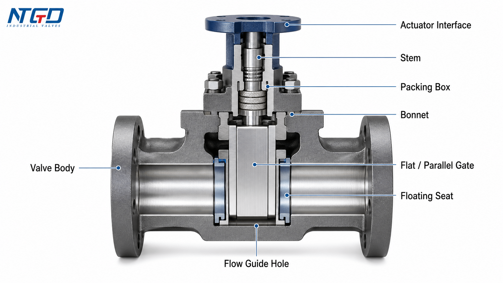
Kluczowe komponenty
| Komponent | Funkcja |
|---|---|
| Korpus zaworu | Houses the flow passage, seats, and gate travel area |
| Maska | Encloses the upper valve structure and supports the stem arrangement |
| Flat / parallel gate | Provides the flat gate geometry that slides between the seat surfaces |
| Single or double gate construction | Defines whether shutoff is handled by one gate plate or by two plates with a supporting / spreading mechanism |
| Floating seat | Helps maintain pressure-assisted seat contact and supports bidirectional shutoff |
| Łodyga | Transfers manual, gear, pneumatic, or electric actuator motion to the gate |
| Packing box | Seals around the stem to reduce external leakage risk |
| Flow guide hole | Aligns with the bore in open position to support pig passage, reduce obstruction, and lower unnecessary pressure loss |
| Interfejs siłownika | Allows manual, gear-operated, pneumatic, or electric operation depending on duty and accessibility |
Single Gate and Double Gate Construction
A single-gate flat gate valve uses one flat gate plate as the closing member. It is simpler and can be suitable for many pipeline isolation duties where the sealing requirement, pressure class, and operating frequency are within the valve’s design range.
A double-gate flat gate valve uses two gate plates with a supporting or spreading mechanism between them. The spreading mechanism helps combine mechanical assistance with the seat contact generated by medium pressure, improving shutoff stability in services where bidirectional sealing or more stable seat engagement is required.
How the Valve Opens and Closes
When the valve is open, the gate moves out of the flow path. In a through-conduit or guide-hole design, the bore of the valve can align with the pipeline bore, creating a more continuous flow path.
When the valve is closed, the flat gate moves into the seat area and blocks the passage. The sealing force is not only mechanical. In many designs, medium pressure acts on the floating gate or floating seat, helping press the sealing surfaces together.
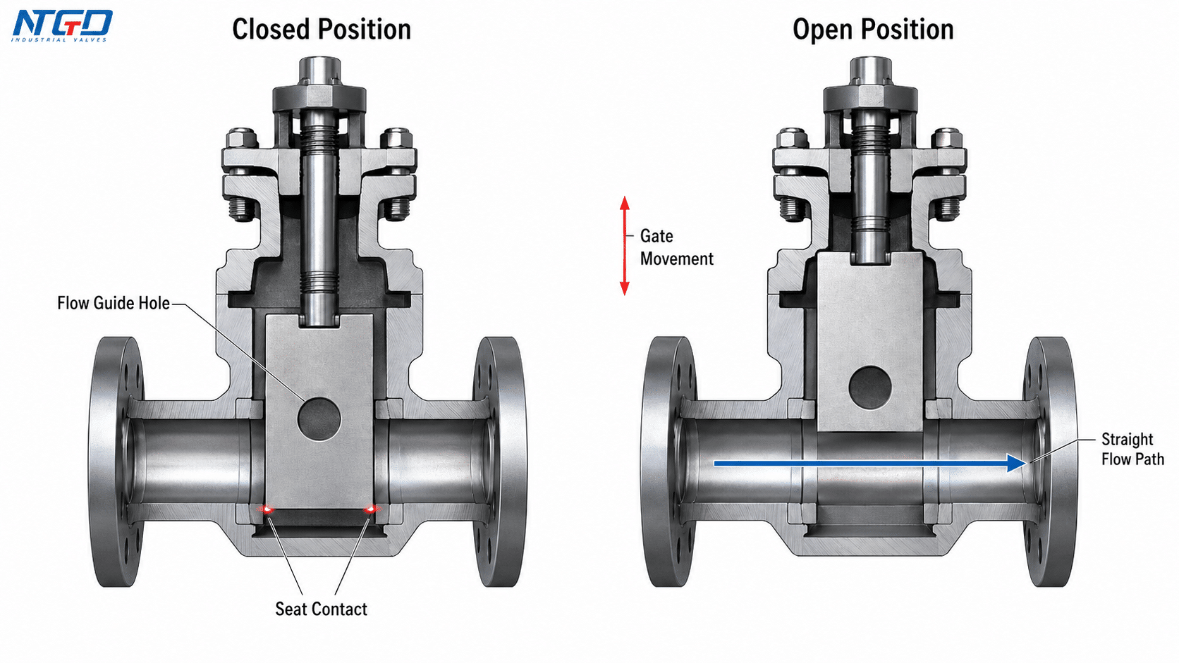
Flow Guide Hole, Through-Conduit Passage, and Pigging
For piggable pipelines, the through-conduit gate valve route makes the flow guide hole a selection-critical feature. When the valve is fully open, the guide hole should align with the pipeline bore so that the pig can pass through the valve with less obstruction. This alignment also helps reduce local flow disturbance and unnecessary pressure loss.
A flat gate valve without a flow guide hole can still be suitable for shutoff service, storage systems, or applications where pipeline cleaning by pig is not required. The decision should come from the pipeline cleaning requirement, medium condition, operating frequency, and pressure envelope—not from the valve name alone.
Cavity Pressure Relief
Some flat gate valve designs can relieve high pressure trapped inside the valve cavity when the valve is closed. Trapped cavity pressure can result from pressure accumulation after shutoff, temperature change, or medium expansion. In oil and gas pipelines, finished oil storage, and wellhead-type service, cavity pressure behavior can affect operating load, sealing stability, and maintenance safety.
The specific cavity relief path depends on the valve design. It should not be assumed without reviewing the manufacturer’s construction and the applicable project specification.
Seat and Seal Mechanism: Floating Seat, Pressure-Assisted Sealing and Grease Injection
The sealing system is one of the most important differences between a flat gate valve and a basic gate valve. A flat gate valve does not rely only on a wedge pushing into angled seats. Instead, sealing is created by the interaction between the flat gate, seat surfaces, medium pressure, pre-tightening force, and auxiliary sealing systems.
Floating Gate and Floating Seat
In a floating-seat flat gate valve, the seat can move slightly under pressure to maintain contact with the gate. In some constructions, the medium pressure acts on the floating gate or floating valve seat and increases the clamping force between the sealing surfaces.
This pressure-assisted behavior helps the valve maintain bidirectional sealing when the seat design, pressure condition, and service medium are properly matched.
O-Ring, Pre-Tightening Force, and Bidirectional Sealing
Many flat gate valves use an O-shaped sealing ring together with a floating valve seat. The seat may be assembled with pre-tightening force so that initial sealing contact exists before full system pressure is applied.
This arrangement supports:
- bidirectional shutoff;
- lower operating torque compared with some ordinary gate valve structures;
- more stable seat contact;
- better sealing reliability when the valve is used for isolation service.
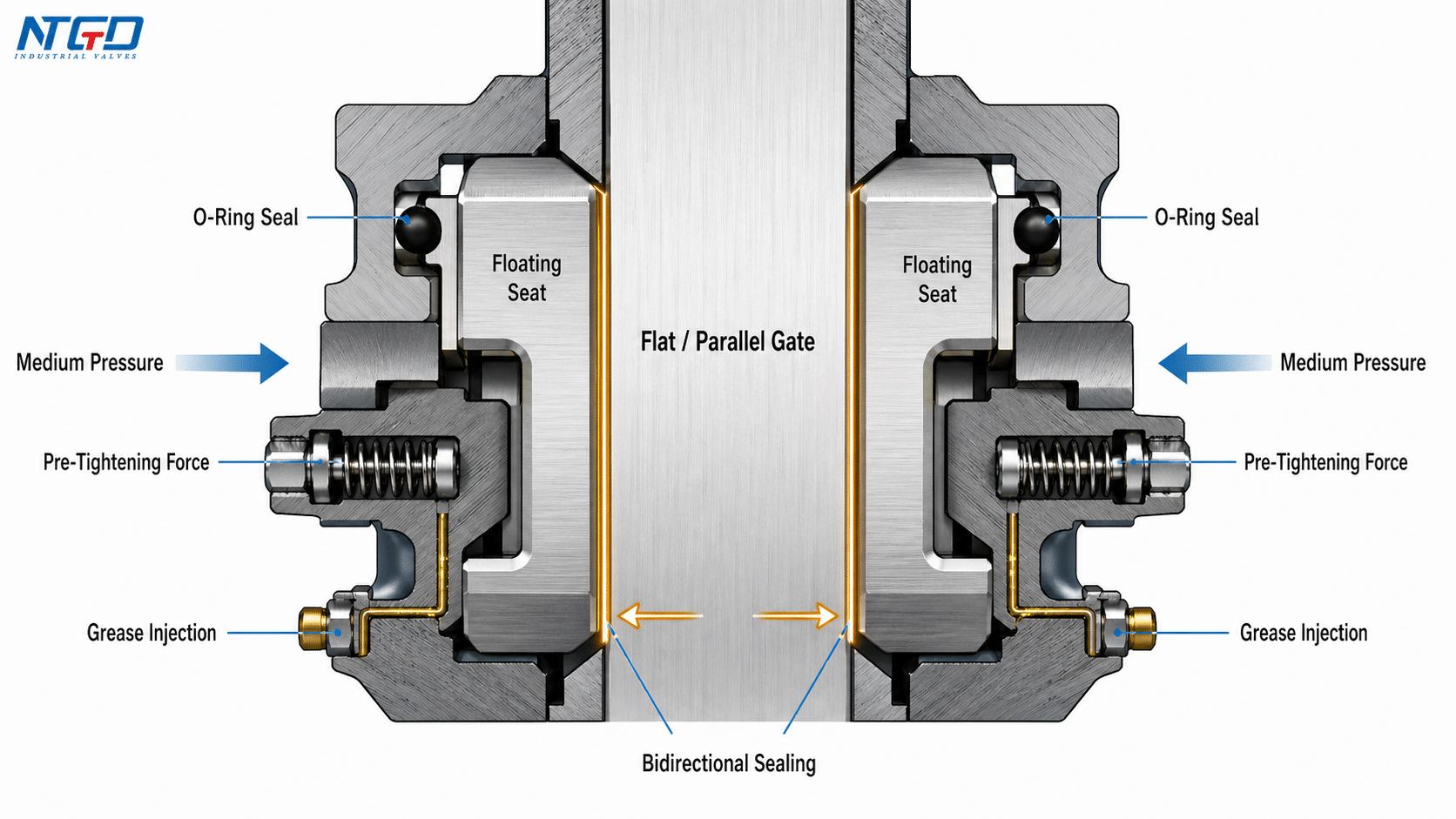
Packing, Grease Injection, and Leakage Control
The stem packing area is another critical leakage path. Flat gate valves may use a self-sealing packing structure that does not require frequent adjustment. Some designs also include an auxiliary sealing grease injection structure at the packing box or sealing area.
Grease injection can help improve sealing reliability, reduce leakage risk, and protect sealing surfaces, especially in oil, gas, dusty, or particle-containing services.
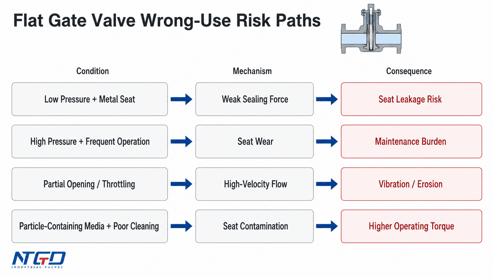
Why Low-Pressure Sealing Can Be Less Reliable
The same pressure-assisted sealing logic also creates a limitation. If the medium pressure is too low, the force pressing the metal sealing surfaces together may not be enough for tight shutoff, especially in metal-seated gate valve projekty.
If a low-pressure service still uses a sealing route that depends heavily on medium pressure, the result may be poor isolation reliability, uncertain seat leakage performance, or difficulty passing site shutoff verification. For low-pressure service with strict leakage expectations, the seat design, soft-seated construction, preload design, and leakage requirement should be reviewed before selection.
Engineering Advantages and Where They Matter
Flat gate valves are selected because their structure provides practical advantages in pipeline and industrial isolation service. Those advantages only matter when the service actually needs them.
| Engineering Advantage | Dlaczego to ma znaczenie | Typical Service Relevance |
|---|---|---|
| Low flow resistance | The flow path can be smooth and straight when fully open | Long-distance crude oil, natural gas, and product pipelines where pressure loss matters |
| Pigging capability | A guide-hole or through-conduit design allows pipeline cleaning tools to pass | Piggable pipelines where full-bore continuity is required |
| Lower operating torque | The sliding gate and floating seat arrangement can reduce open-close effort | Large manual valves, gear-operated valves, and electric flat gate valves where actuator torque margin matters |
| Bidirectional sealing | Floating seat and pressure-assisted sealing can support shutoff from either direction | Pipeline isolation, storage, and wellhead service |
| Seat self-positioning | Seat contact can remain more stable under body deformation or thermal effects | Temperature-variable pipeline systems |
| Cavity pressure relief | Helps reduce trapped-pressure risk when the valve is closed | Oil and gas pipeline, finished oil storage, and wellhead-type applications |
| Enclosed structure | Protects moving parts against outdoor and all-weather conditions | Field pipelines, gas networks, and municipal systems |
Low Flow Resistance in Transmission Pipelines
When fully open, a flat gate valve can provide a smoother passage than many obstructive shutoff designs. In long-distance transmission, that matters because unnecessary pressure loss increases system load and reduces pipeline efficiency.
Pigging Capability with a Flow Guide Hole
For pipelines that require pigging, the flow guide hole is not a minor accessory. It determines whether the valve can support pig passage without creating a major obstruction. This is one of the strongest reasons to choose a through-conduit or guide-hole flat gate valve.
Lower Operating Torque and Easier Operation
The flat gate and floating seat structure can reduce opening and closing torque, but actuator sizing still needs careful review. Torque demand can rise with seat friction, differential pressure, stem resistance, particle accumulation, or insufficient lubrication. This is especially important for large valves and electric flat gate valves.
Limitations, Wrong-Use Risks and Maintenance Considerations
A flat gate valve is mainly an isolation valve. It can perform well in pipeline shutoff, piggable service, oil and gas systems, and selected municipal or industrial applications, but it should not be treated as a universal flow-control valve.
Low-Pressure Sealing Limitations
In low-pressure service, metal-to-metal sealing may not develop enough contact force for tight shutoff. If the system requires low-pressure zero-leakage performance, the seat design must be reviewed carefully.
Soft-seated exposed-stem flat gate valves may be more suitable for some gas or municipal services, while metal-seated designs may be better suited for higher pressure or more severe services.
High-Pressure Frequent-Operation Wear
When pressure is high and the valve is opened and closed frequently, the sealing surfaces may wear faster. This risk increases if the medium does not provide enough lubrication, if particles accumulate around the seat area, or if the valve is operated under high differential pressure.
External lubrication, proper grease injection, and suitable seat materials can reduce this risk, but they do not turn the valve into a frequent-cycling control valve.
Not a Primary Throttling Valve
Like other isolation-focused gate valve designs, a flat gate valve is not normally selected as a primary throttling valve. When the gate is partially open, high-velocity flow can concentrate on the gate edge and seat surface. That can cause erosion, vibration, unstable control, seal damage, and internal leakage.
Some special V-port or closely guided designs may provide limited throttling capability, but that should be treated as a special design boundary. It should not be considered standard flat gate valve service.
Vibration Under High-Speed or High-Density Flow
When the gate obstructs high-speed or dense media flow, vibration may occur. This is especially important in particle-containing pipelines or applications where the valve is incorrectly used in a partially open position.
The practical risk is not only noise. Severe vibration and erosion can shorten seat life, damage sealing surfaces, increase operating torque, and lead to unplanned maintenance.
Uwagi dotyczące konserwacji
Flat gate valves should be maintained with attention to:
- packing condition and stem sealing;
- grease injection points;
- seat surface cleanliness;
- particles trapped around the gate or seat;
- actuator stroke setting if electric;
- manual override function if electric actuation is used;
- corrosion protection during storage or outdoor service.
A wrong selection can lead to poor shutoff reliability, seat leakage, accelerated wear, actuator overload, or unplanned maintenance. Selection should not stop at valve name and pressure class. The medium, pressure differential, operating frequency, seat design, lubrication route, and actuation margin must be checked together.
How to Select a Flat Gate Valve by Application
Flat gate valve selection should start from the service condition. The key question is what the valve needs to isolate, how often it will operate, whether the pipeline needs pigging, and what shutoff reliability the system expects.
| Zastosowanie | Recommended Construction | Guide Hole Requirement | Key Reason | Caution |
|---|---|---|---|---|
| Petroleum and natural gas transmission pipelines | Single gate or double gate flat gate valve | Use guide hole if pigging is required | Low resistance and full-bore passage support transmission service | Do not select by nominal pressure alone; confirm pigging need, seat design, differential pressure, temperature, and medium condition |
| Finished oil transportation and storage | Single or double gate flat gate valve | Often without guide hole if pigging is not required | Reliable shutoff for storage and transfer systems | Avoid over-specifying through-conduit construction when pipeline cleaning is not required; it can add complexity without adding service value |
| Oil and gas wellhead / Christmas tree | Hidden-stem floating-seat flat gate valve | Usually with flow guide hole | High-pressure shutoff and oilfield service requirements | Treat this as oilfield service; API16A-type requirement, pressure route, stem design, and seat design must be reviewed separately from ordinary pipeline service |
| Suspended-particle service | Flat gate valve with suitable seat and sliding gate design; knife-type route only if required | Depends on particle size and service duty | Sliding gate can tolerate some particle-containing media | Do not convert this into generic knife gate valve selection; verify particle size, abrasion, seat protection, and cleaning access |
| Urban gas transmission | Soft-sealed exposed-stem flat gate valve | Zależne od aplikacji | Soft sealing and accessible stem design can support gas network operation | Leakage expectation, operating pressure, maintenance access, and stem arrangement should be checked before selection |
| Municipal water projects | Single or double gate exposed-stem flat gate valve | Often without guide hole | Lower pressure and easier operation are usually more important than pigging | Do not treat it as a general waterworks valve without reviewing pressure, corrosion, operation frequency, and maintenance access |
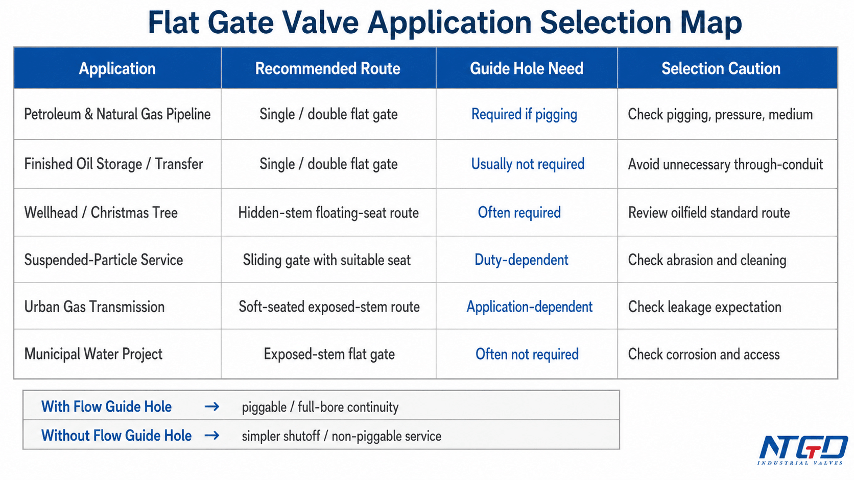
With Guide Hole vs Without Guide Hole
| Design Route | Najlepsze dopasowanie | Główna zaleta | Główne ograniczenia |
|---|---|---|---|
| With flow guide hole | Piggable pipelines, oil and gas transmission, some wellhead service | Maintains a smoother bore and allows pigging | More construction complexity |
| Without flow guide hole | Storage, finished oil transfer, municipal or non-piggable service | Simpler construction where pigging is not needed | Not suitable for pipeline cleaning by pig |
Pipeline Route vs Wellhead Route
Pipeline service and wellhead service should not be mixed into one selection rule.
For pipeline service, the discussion usually focuses on low flow resistance, pigging, pressure class, and through-conduit design. For wellhead or Christmas tree service, the discussion shifts toward high pressure, API16A-type requirements, stem arrangement, floating seat behavior, and reliable shutoff under oilfield conditions.
Specifications, Standards, Materials and Construction Options
A technical guide should not become a catalog, but B2B buyers still need enough specification guidance to judge whether the valve family fits the operating envelope.
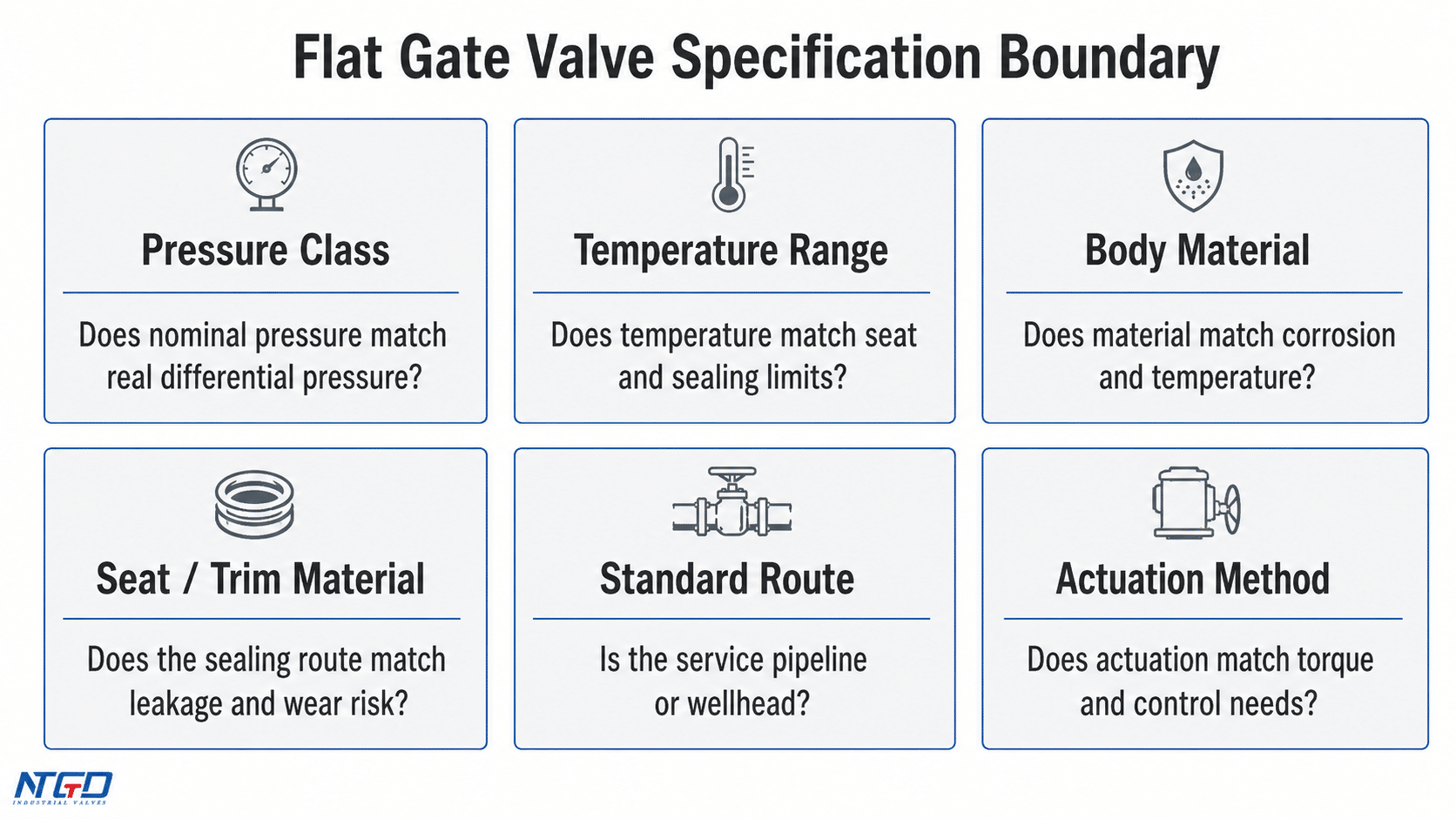
Typical Specification Boundaries
| Pozycja | Typical Consideration |
|---|---|
| Klasa ciśnienia | Class 150–900LB or PN1.0–16.0MPa may be used in common pipeline flat gate valve ranges; higher oilfield pressure classes require separate project review |
| Temperatura pracy | -29°C to 121°C is a common reference range in many standard services; higher or lower temperatures require material, seat, and sealing review |
| Zakres rozmiarów | Confirm by project specification and verified manufacturing capability rather than assuming from the valve type alone |
| Materiał korpusu | Carbon steel, low-temperature carbon steel, stainless steel, or alloy materials should be matched to pressure, temperature, corrosion, and medium condition |
| Materiał siedzenia / wykończenia | Select according to leakage expectation, wear risk, corrosion, pressure condition, and operating frequency |
| Uruchomienie | Manual, gear-operated, pneumatic, or electric operation should be selected by accessibility, automation need, torque margin, and operating duty |
Specification review should connect the service medium, pressure, temperature, seat design, valve inspection and testing requirements, leakage expectation, wybór materiału zasuwy, operating frequency, and actuation method. A valve that fits the nominal pressure class may still be unsuitable if the seat route, material, or actuation margin does not match the real duty.
Standards Boundary
| Service Route | Relevant Standard Direction | Uwaga dotycząca wyboru |
|---|---|---|
| Pipeline service | API 6D / ASME B16.34 / API 598 may be relevant depending on specification | Confirm design, testing, pressure class, and end connection requirements |
| Wellhead / Christmas tree service | API standards for wellhead and Christmas tree equipment may apply | Do not apply ordinary pipeline valve logic directly to wellhead service |
| General industrial service | Project specifications and applicable valve standards should be reviewed | Pressure, temperature, material, and leakage expectations must align |
Construction Options
Flat gate valves may be supplied as:
- single-gate or double-gate designs;
- with or without flow guide hole;
- through-conduit or non-through-conduit route;
- rising stem or hidden / non-rising stem route;
- manual, gear, pneumatic, or electric actuation;
- soft-seated or metal-seated construction depending on service conditions.
The correct configuration depends on the medium, operating pressure, pigging requirement, leakage expectation, operating frequency, and installation environment.
Electric Flat Gate Valve: When Electric Actuation Fits
An electric flat gate valve is a flat gate valve equipped with an electric actuator to control stem travel and gate movement. The actuator does not change the valve’s basic sealing principle; it changes how the valve is operated, monitored, and integrated into the control system.
Electric actuation is useful when the valve is large, difficult to access, part of an automated pipeline, or required to operate from a control room. It is also relevant where position feedback, interlocks, emergency shutdown logic, or SCADA / DCS integration are required.
How Electric Operation Works
In a typical electric flat gate valve, the control signal activates the siłownik elektryczny. The actuator motor drives a gearbox or worm gear mechanism, which turns the stem or stem nut. That motion moves the gate between open and closed positions.
| Krok | Funkcja |
|---|---|
| Control command | Sent from a local panel, remote control, PLC, DCS, or SCADA system |
| Electric motor | Provides driving power |
| Gearbox / worm gear | Converts motor output into controlled valve movement |
| Ruch trzpienia | Transfers actuator movement to the gate |
| Gate movement | Otwiera lub zamyka kanał przepływu |
| Limit switch / position feedback | Confirms open, closed, or intermediate position |
| Torque protection | Stops operation if abnormal resistance occurs |
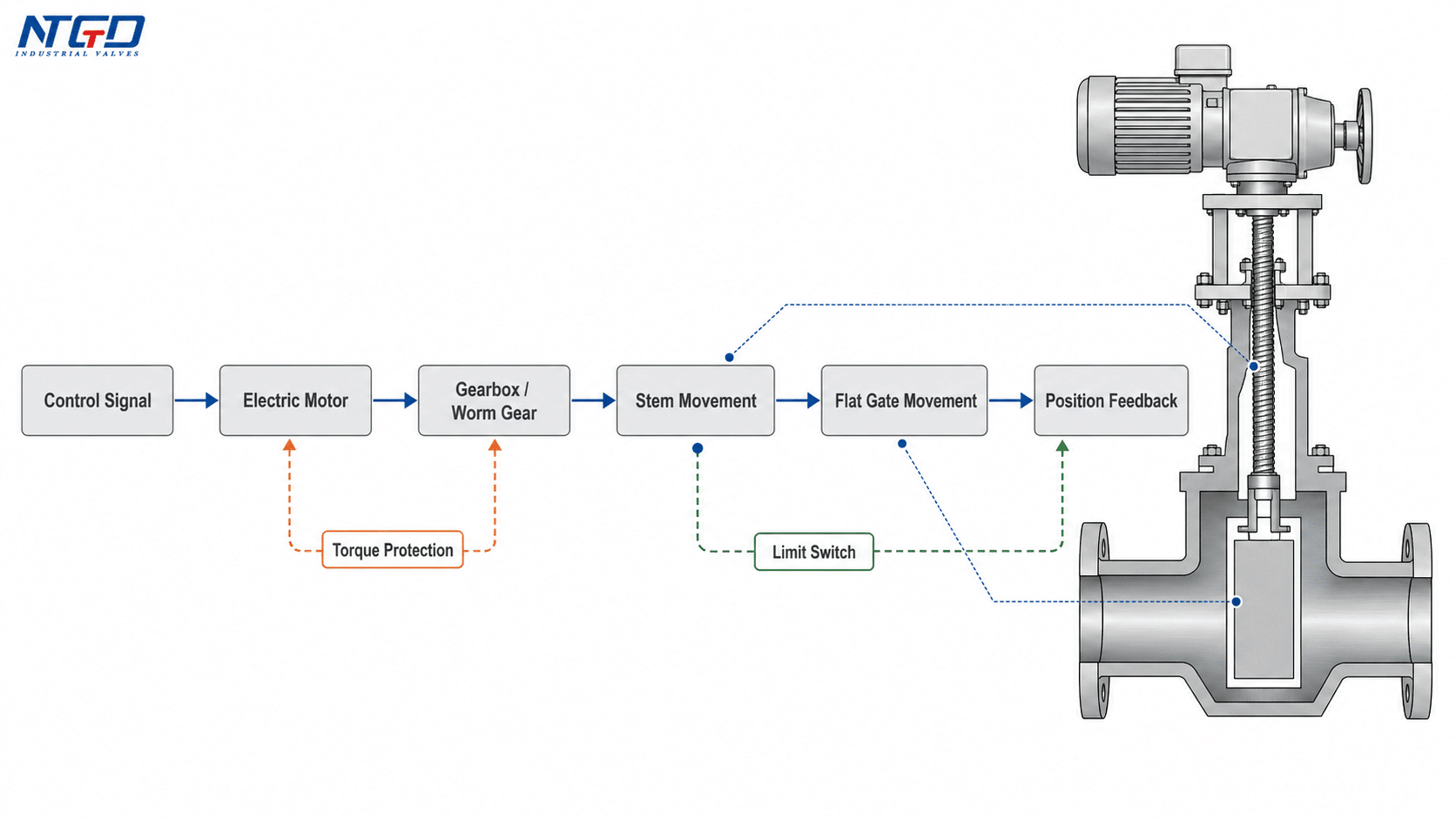
Limit Switch, Stroke Control and Torque Protection
Electric flat gate valves need accurate stroke control. If the actuator stops too early, the valve may not fully open or close. If it drives too far or pushes against abnormal resistance, the stem, gate, seat, or actuator may be damaged.
Limit switches help confirm the open and closed positions. Torque protection helps prevent overload when seat friction, pressure load, debris, or stem resistance increases.
Electric vs Manual vs Pneumatic Flat Gate Valve
| Typ aktywacji | Najlepsze dopasowanie | Main Consideration |
|---|---|---|
| Podręcznik | Small or accessible valves with low operation frequency | Lowest control complexity, but requires local operation and operator access |
| Gear-operated | Larger valves where manual torque must be reduced | Practical for field service, but slower and still requires local operation |
| Pneumatyczny | Fast operation where compressed air is available | Requires reliable air supply, accessories, and control logic |
| Elektryczny | Remote operation, large valve size, difficult access, automated pipeline isolation, ESD / interlock requirement | Requires power supply, torque margin, limit switch setting, position feedback, manual override, and control system integration |
Electric actuation should be selected for a control requirement, not only because the valve is large. For rarely operated, accessible isolation valves, manual or gear operation may still be more practical. For automated pipeline isolation, remote shutoff, or digital field management, an electric flat gate valve can provide a stronger fit—provided torque, stroke, seat friction, and control feedback are reviewed together.
FAQ
Is a flat gate valve the same as a slab gate valve?
The terms overlap in many oil, gas, and pipeline contexts. A slab gate valve usually points to a flat gate design with through-conduit or full-bore construction, especially where pigging and low flow resistance are required.
What should I verify when a supplier quotes a flat plate gate valve?
Do not stop at the name. Check whether the quoted valve uses a single gate, double gate, slab or expanding route, with or without flow guide hole, metal or soft seat, and which standard route applies. The term flat plate gate valve describes the closing element, but the construction details determine whether it fits the service.
Can a flat gate valve be used for pigging?
Yes, but the valve should use a flow guide hole or through-conduit design. A flat gate valve without a guide hole may still provide shutoff, but it may not provide the bore continuity needed for pig passage.
Why does a piggable pipeline need a flow guide hole?
The flow guide hole helps the open valve bore align with the pipeline bore. This allows the pig to pass through the valve with less obstruction and helps reduce unnecessary pressure loss in full-bore service.
When should an electric flat gate valve be used?
Use an electric flat gate valve when the service needs remote operation, automation, position feedback, interlock logic, difficult-access operation, or PLC / DCS / SCADA integration. For accessible valves with low operating frequency, manual or gear operation may be more practical.
What happens if a flat gate valve is used for throttling?
Long-term throttling can expose the gate edge and seat surfaces to high-velocity flow. The likely result is vibration, erosion, unstable control, seal damage, internal leakage, or early maintenance.
Why can low-pressure sealing be a concern in a flat gate valve?
Some flat gate valve sealing systems depend partly on medium pressure to help press the gate and seat together. If pressure is too low, especially in metal-seated designs, the valve may not develop enough sealing force for strict shutoff expectations.
Wnioski
A flat gate valve should be selected as an isolation valve when the service requires a straight flow path, low pressure loss, reliable shutoff, and in some cases pigging capability. Its value comes from the combination of a flat or parallel gate, floating seat behavior, pressure-assisted sealing, and application-specific construction such as guide-hole or through-conduit design.
The best selection is not based on the valve name alone. Pipeline transmission, finished oil storage, wellhead service, suspended-particle media, urban gas, and municipal water systems all require different construction choices. Seat design, pressure class, temperature range, guide-hole requirement, stem arrangement, standard route, and actuation method must be reviewed together.
A flat plate gate valve or slab gate valve may refer to the same practical valve family in product and pipeline contexts, but the final specification must still match the service. Electric actuation can add remote control and automation, but it should support the flat gate valve’s operating duty rather than turn the selection into an actuator-only decision.
Końcowe sprawdzenie aplikacji
When the selection is not straightforward—especially where pigging, low-pressure sealing, wellhead standards, material compatibility, or electric actuation are involved—an application-specific engineering review is the safer route.
For buyers comparing a flat gate valve manufacturer, factory, or supplier, the useful starting point is not price alone but a verified service specification. Prepare the service medium, pressure class, temperature range, pipeline cleaning requirement, preferred standard, material requirement, and actuation method. NTGD Valve can help review whether a manual, gear-operated, pneumatic, or electric flat gate valve configuration is suitable for your pipeline, wellhead, gas, water, or industrial isolation service.
