Thermostatic Steam Trap: Working Principle, Selection Guide & Common Failures
Thermostatic steam traps operate on one simple idea: steam is hotter than condensate and air. The trap uses this temperature difference to open for cooler condensate/air and close when live steam reaches the element. That is why thermostatic traps are widely used where start-up air removal and light-to-medium condensate loads dominate.
Steam traps are generally classified into mechanical, thermodynamic, and thermostatic types according to their operating principle, as commonly defined in industrial engineering references such as Wikipedia’s steam trap overview .
Best fit (typical):
• Steam tracing
• Heating coils & unit heaters
• Sterilizers / small process heaters
• Low-load steam systems where air venting is critical
Core advantage:
Excellent air venting during cold start-up (reduces air binding and improves warm-up stability).
Core limitation:
Thermostatic traps discharge condensate at a temperature below saturated steam temperature (subcooling). For duties requiring immediate condensate removal with zero waterlogging, thermostatic may not be the primary best choice.
Want a complete guide to all steam trap types and their applications? See our Steam Trap Overview & Buying Guide, covering Thermostatic, Thermodynamic, Inverted Bucket, and Ball Float Steam Traps for industrial steam systems.
Request a Free Quote & Selection Support
Response within 24 hours | Free engineering consultation | MTC/Test reports available
Email: [email protected] | WhatsApp: +86 138 6860 3320
——————————————————————
Quick Comparison: Thermostatic vs Thermodynamic vs Inverted Bucket
| Steam Trap Type | Core Working Principle | Best Fit Applications | Air Venting | Discharge Style | Backpressure Tolerance (Typical) | Freeze Resistance (Typical) | Primary Failure Tendency |
|---|---|---|---|---|---|---|---|
| Thermostatic Steam Traps | Temperature difference between steam and cooled condensate/air | Tracing, coils, sterilizers, unit heaters | Excellent | Intermittent; below saturation discharge | Balanced pressure: medium; Bimetallic: higher | Bimetallic models: strong | Fail closed when backpressure/installation incorrect; leak when seat worn/dirt present |
| Thermodynamic (Disc) | Flash steam / velocity closes disc | Steam mains drip legs, high pressure outdoor duty | Medium | Intermittent “blast” | Medium (system dependent) | Good (if drains well) | Frequent cycling at low load; performance shifts with backpressure |
| Inverted Bucket Steam Traps | Buoyancy / density difference (mechanical) | Dirty service, rugged process duty, water hammer tolerance | Moderate | Mechanical intermittent | Higher in many systems | Moderate to low (depends on drainage) | Lose prime / fail open if venting or piping incorrect |
Explore related pages (recommended reading):
• Steam Trap Overview (Hub): https://ntgdvalve.com/steam-trap/
• Thermodynamic Steam Trap: https://ntgdvalve.com/thermodynamic-steam-trap/
• Inverted Bucket Steam Trap: https://ntgdvalve.com/inverted-bucket-steam-trap/
——————————————————————
60-Second Selection Rules (Engineering Quick Pick)
Choose a thermostatic steam trap when:
• Start-up air removal matters (air binding causes underheating and unstable control)
• Condensate load is light to medium (common in tracing and coils)
• Some subcooling is acceptable
Avoid or re-check selection when:
• The equipment cannot tolerate waterlogging (critical exchangers, some mains drainage)
• Return line backpressure is high or unstable
• Installation cannot provide a proper cooling leg where required
Non-negotiable in real projects:
• Evaluate differential pressure (ΔP) using inlet pressure minus return line backpressure
• Install upstream strainer when dirt/scale is expected
• Confirm installation direction, maintenance access, and drainage logic
——————————————————————
Specifications
| Size Range | DN15–DN300 |
| Pressure Class | ANSI 150LB / 300LB; PN10–PN64 |
| Design Standard | ASME B16.34; DIN 3202 |
| End Connection | Flanged / BW / Thread |
| Typical Materials | Carbon Steel, Stainless Steel, Bronze |
——————————————————————
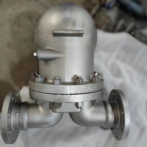
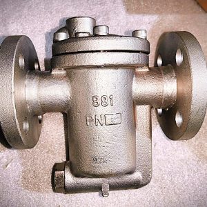
What Is a Thermostatic Steam Trap?
A thermostatic steam trap is a steam trap that opens and closes based on temperature difference between steam and cooler condensate/air. When steam reaches the element, the element expands and closes the valve. When condensate/air cools the element, it contracts and opens the valve to discharge condensate and vent air.
The biggest practical value is air venting at start-up: thermostatic traps can help remove non-condensable gases that otherwise block heat transfer.
——————————————————————
How Does a Thermostatic Steam Trap Work? (Working Principle)

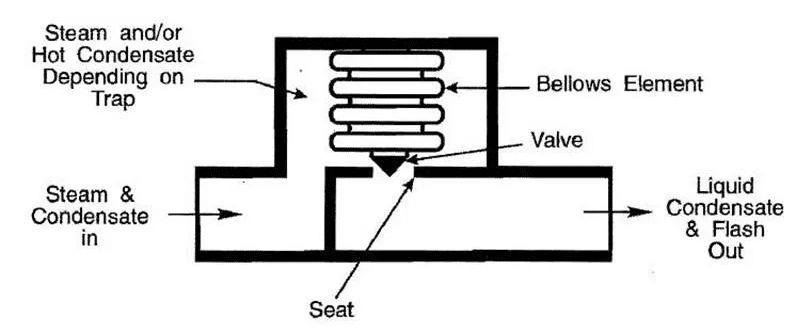
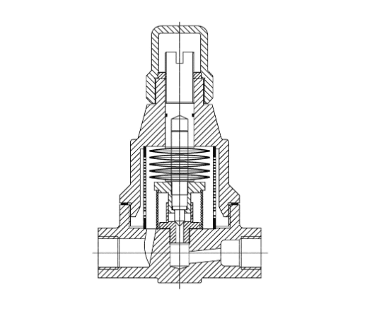
1) Balanced Pressure Bellows / Capsule Type (Most Common)
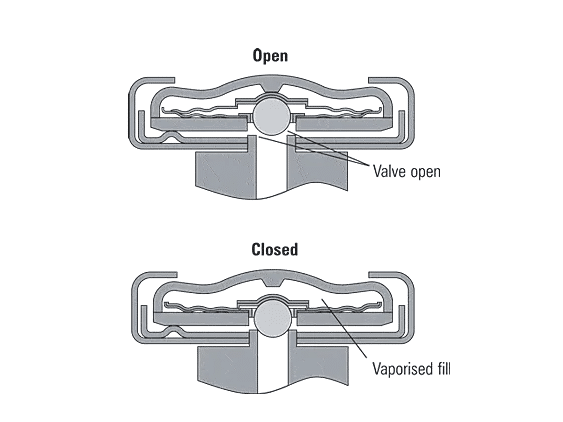
Cold start:
• Element contracted → valve open wide
• Air and cold condensate discharge freely
Approaching steam:
• Element heated → internal fluid vaporizes → element expands → valve closes
Cooling:
• Condensate/air cool element → element contracts → valve opens again
Why it matters:
This cycle is excellent for air venting, but the trap may remain closed until condensate temperature drops below saturation temperature by several degrees (subcooling).
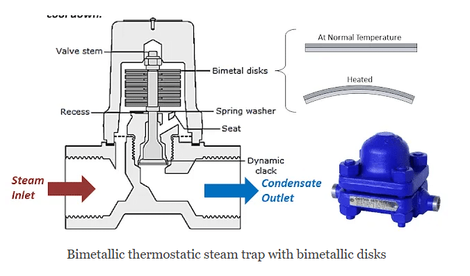
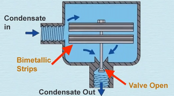
2) Bimetallic Thermostatic Type

A bimetallic element bends when heated and returns when cooled:
• More rugged design
• Wider pressure tolerance in many real installations
• Often better for outdoor/freeze risk and higher backpressure return systems
3) Liquid Expansion Type (Shutdown Drain / Special Duty)
This type uses liquid expansion with a fixed discharge temperature setpoint (commonly in the 60–100°C range):
• Strong cold drain behavior
• Typically used for shutdown drain or start-up drainage in specific systems
• Not intended as a universal replacement for balanced pressure or bimetallic models
For a visual explanation of how different steam trap types operate, you may also refer to this educational overview video
——————————————————————
Deep Engineering Concept 1: Subcooling (Why Thermostatic Traps Discharge Below Saturation)
Subcooling is the temperature difference between saturated steam temperature and the condensate discharge temperature. Thermostatic traps require subcooling to trigger the element to open.
Practical meaning:
• Higher subcooling → better energy recovery but slower drainage
• Lower subcooling → faster drainage but may increase steam loss risk if improperly selected
Typical guidance:
• Tracing and unit heating can tolerate more subcooling.
• Some process heating duties require tighter temperature control and may tolerate less waterlogging, so selection must be conservative.
If a user says “the trap doesn’t drain fast enough,” the cause is often not the trap itself but either:
• insufficient subcooling/cooling leg conditions, or
• high backpressure reducing the effective ΔP.
——————————————————————
ΔP and Backpressure (The #1 Reason for “Trap Not Discharging” Complaints)
In field operation, capacity and discharge behavior depend heavily on differential pressure:
ΔP (differential pressure) = Inlet pressure – Return line backpressure
What backpressure changes:
• Reduces ΔP → reduces discharge capacity
• Can shift the trap into “stays closed longer” behavior
• Can cause intermittent discharge, air binding, or perceived underheating
Fast checks to confirm backpressure issues:
• Is the return line lifted vertically after the trap? (creates static head and backpressure)
• Is the condensate return header frequently pressurized by flash steam?
• Is there a vacuum condition or unstable return line?
If your return line is a high backpressure system, bimetallic thermostatic traps are often preferred compared to standard balanced pressure models.
——————————————————————
Thermostatic Steam Trap Selection Guide (Bellows vs Bimetal vs Liquid Expansion)
Step 1 — Define Your Duty Inputs (RFQ Must-Have)
To size and select correctly, provide:
• Steam pressure: minimum / normal / maximum
• Condensate load: start-up peak and normal load
• Return system: backpressure, lift, recovery method
• Dirt/scale risk and maintenance access
• Installation environment: indoor/outdoor, freeze risk, water hammer risk
• Required connection and materials
Step 2 — Choose Type by Application
Balanced Pressure (Capsule/Bellows) is best when:
• Air venting performance is the top priority
• Load is light to medium
• You need stable operation across common industrial pressures
Bimetallic is best when:
• Return line backpressure is high
• Outdoor/freeze risk exists
• More rugged resistance to field abuse and water hammer is required
Liquid Expansion is best when:
• You need a shutdown drain or fixed-temperature discharge behavior in a specific system design
Step 3 — Verify System Limits (Avoid Misapplication)
• Confirm ΔP under minimum operating conditions
• Confirm return line backpressure behavior during start-up and steady load
• Avoid selecting based on line size alone (line size ≠ required capacity)
• Install strainer and ensure blowdown access where dirt is expected
Step 4 — Sizing Rule (Simple, Field-Safe)
Required trap capacity = Actual condensate load × safety factor
Typical safety factors:
• 1.5× for steady normal operation
• 2–3× for start-up peak load
• Higher factor when pressure fluctuates widely or backpressure is unstable
This simple rule prevents undersizing (poor drainage) and oversizing (excess cycling and seat wear).
——————————————————————
Steam Trap Load Selection Quick Table (Fast Match by Duty)
| Load / Duty Pattern | Recommended Thermostatic Type | Why It Fits | Key Watch-outs |
|---|---|---|---|
| Light load + lots of air at start-up (common) | Balanced pressure (capsule/bellows) | Best air venting and start-up performance | Verify backpressure and cooling leg conditions |
| Outdoor duty / freeze risk / higher backpressure return | Bimetallic | Rugged, good drainage behavior and better tolerance in many return systems | Still verify ΔP and installation drainage |
| Shutdown drain / fixed discharge temperature approach | Liquid expansion | Fixed setpoint behavior supports special drain logic | Not a universal replacement for process drainage |
| Start-up peak load is very high | Balanced pressure + correct sizing (often with safety factor 2–3×) | Wide-open start-up venting and high initial discharge | Upstream strainer mandatory; avoid oversizing |
——————————————————————
Common Thermostatic Steam Trap Failures
| Observed Symptom | Most Likely Root Causes | Step-by-Step Corrective Action (Field) | Prevention |
|---|---|---|---|
| No condensate discharge (trap body cold) | 1) Isolation valves not fully open 2) Strainer/line blockage 3) Excessive backpressure / insufficient ΔP 4) Failed capsule/bellows / element stuck closed 5) Incorrect installation direction or missing cooling conditions |
1) Confirm inlet/outlet valves fully open and flow direction correct 2) Clean strainer and inspect seat area for debris 3) Check return line lift/pressurization; verify ΔP at minimum operating pressure 4) Replace thermostatic element if no movement is detected (see Field Test below) 5) Correct piping, ensure proper drainage logic and required cooling leg conditions |
Install upstream strainer + blowdown; verify backpressure envelope at design stage; avoid insulating critical upstream cooling sections when applicable |
| Continuous live steam leakage (blowing) | 1) Dirt trapped on seat 2) Seat/valve wear or erosion 3) Oversized trap causing frequent cycling 4) Damaged thermostatic element/capsule |
1) Isolate and clean seat/valve area 2) Replace worn components or maintenance kit 3) Re-check sizing based on actual load and ΔP 4) Replace element/capsule if damaged |
Do not oversize; add strainer; verify capacity at minimum pressure; schedule periodic inspection for high-cycle duty |
| Underheating / poor heat transfer | 1) Air binding (non-condensables not vented properly) 2) Trap failing closed due to backpressure 3) Insufficient drainage due to piping pitch or pooling 4) Trap undersized for peak load |
1) Confirm trap type supports strong air venting (balanced pressure is preferred for air removal) 2) Verify return line backpressure and ΔP 3) Check piping slope to the trap and remove pooling points 4) Re-size for start-up peak load using 2–3× safety factor |
Use correct trap type per duty; ensure proper placement and slope; verify backpressure under real operating conditions |
| Water hammer / abnormal noise | 1) Condensate pooling due to inadequate drainage 2) Trap malfunction or wrong trap for application 3) Start-up air and condensate not cleared effectively |
1) Improve drainage design and place trap close to condensate source 2) Validate selection type and confirm operation by temperature/ultrasonic checks 3) Ensure start-up venting is adequate; use balanced pressure thermostatic where air venting is needed |
Design for drainage first; don’t group-trap multiple equipment; keep maintenance access and inspection routine |
| Outdoor freeze damage / cracked body | 1) Condensate retained in body during shutdown 2) Poor drainage orientation 3) Wrong type for exposure conditions |
1) Confirm self-draining installation orientation and shutdown drainage 2) Consider bimetallic type for outdoor duty 3) Add proper winterization strategy for piping system |
Choose freeze-tolerant designs; ensure drainage during shutdown; implement winterization plan |
——————————————————————
Cooling Leg (Critical Rule Engineers Often Miss)
A cooling leg is the upstream section that allows condensate temperature to drop enough to trigger thermostatic element opening. Without proper cooling conditions, a thermostatic trap may remain closed longer than expected.
Practical guidance:
• Keep the trap close to the condensate discharge point where possible.
• Ensure piping encourages condensate collection and flow toward the trap.
• Avoid designs that trap steam at the element without allowing adequate cooling where the trap needs temperature difference to open.
Common mistake that causes “fail closed” complaints:
• Insulating or routing piping in a way that prevents condensate from cooling or accumulating properly before the trap.
If you want, send me your typical installation sketch (or tell me “tracing / coil / sterilizer”) and I’ll give you the specific cooling leg placement notes and the “do-not” list for that duty.
——————————————————————
Field Test (Fast Check for Element Failure)
If you suspect the thermostatic element (capsule/bellows/bimetal) is failed, use a simple verification workflow during maintenance:
-
Confirm blockage first
• Clean strainer and check seat area debris before concluding element failure. -
Check temperature behavior
• If inlet is hot and outlet stays cold with no discharge, suspect insufficient ΔP/backpressure or element stuck closed. -
Element movement check (maintenance condition)
• If the element shows no change in behavior across hot/cool conditions during inspection, replacement is recommended.
This “confirm blockage → confirm ΔP/backpressure → confirm element condition” order prevents misdiagnosis and unnecessary replacement.
——————————————————————
Installation Best Practices
• Install a strainer upstream (especially in older lines or systems with scale).
• Confirm flow direction strictly by body arrow.
• Provide isolation valves for safe maintenance.
• Ensure piping slope promotes drainage toward the trap and avoids pooling.
• Evaluate return line backpressure, lift, and flash steam behavior.
• For outdoor installations, ensure the system drains during shutdown and follow winterization practices.
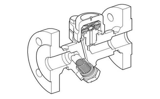
To ensure reliable operation and prevent debris from entering your steam trap, install a high-quality Steam Trap Strainer upstream of the trap.
——————————————————————
Why Choose NTGD
Authored by: NTGD Steam System Engineering Team
Last Updated: 2026-03
NTGD supplies thermostatic steam traps for industrial steam systems where reliable drainage, strong air venting, and traceable documentation matter.
What you receive:
• Compliance basis: ASME B16.34 and DIN 3202 design framework
• Documentation available upon request: Material Test Certificates (MTC), inspection and testing records
• Engineering support: selection guidance based on your duty inputs (pressure, load, backpressure, connection, materials)
RFQ checklist (to quote correctly and fast):
• Steam pressure range (min/normal/max)
• Condensate load (start-up peak + normal)
• Return line backpressure and lift conditions
• Size, connection type, material requirement
• Application: tracing / coil / sterilizer / heater / other
Request a Free Quote & Selection Support
Email: [email protected] | WhatsApp: +86 138 6860 3320
——————————————————————
FAQ
-
What is a thermostatic steam trap best used for?
Steam tracing, heating coils, sterilizers, and unit heaters where strong air venting at start-up is important. -
Why does a thermostatic steam trap discharge below saturation temperature?
Because it requires subcooling (temperature difference) to trigger opening—this is inherent to thermostatic operation. -
Thermostatic vs thermodynamic steam traps: which should I use?
Thermostatic is best for air venting and light-to-medium loads; thermodynamic is commonly used for steam mains drip legs and rugged outdoor duty. -
What causes a thermostatic steam trap to fail closed?
High backpressure, clogged strainer/seat, insufficient ΔP, incorrect installation direction, or a failed thermostatic element. -
Can I insulate a thermostatic steam trap?
You may insulate the body in some systems, but do not insulate or route upstream piping in a way that eliminates the temperature difference needed for proper opening. -
How does backpressure affect thermostatic steam trap performance?
Backpressure reduces ΔP and can delay opening or reduce discharge capacity, causing perceived underheating or “not discharging” complaints. -
Can thermostatic traps handle outdoor freeze risk?
Bimetallic thermostatic traps are commonly preferred for outdoor duty, but correct drainage during shutdown remains essential. -
What information do you need for quotation and selection?
Steam pressure range, condensate load (start-up and normal), return line backpressure/lift, size/connection/material, and the application.
For other industrial steam trap types and applications, see our pages on Thermodynamic Steam Traps, Inverted Bucket Steam Traps, and Ball Float Steam Traps.