NTGD QUALITY CONTROL
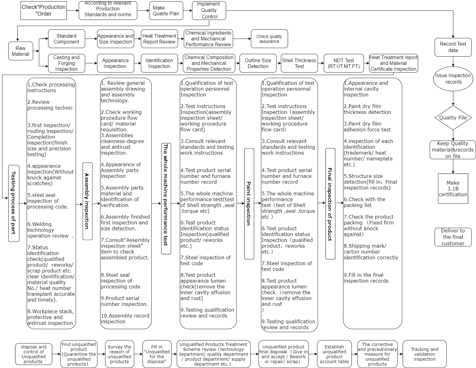
NTGD VALVE QUALITY CONTROL FLOW CHART
NTGD valve has established, document, implement and maintain a full-fledged quality control system and continually improve its effectiveness in accordance with the requirements of ISO9001:2015 standard. To ensure that our Company can continuously provide our customer with the designing, developing, purchasing, manufacturing, delivery, and after-sales service.
QUALITY CONTROL PROCEDURE
Raw Material Inspection
In Process Inspection
Assembling Specification
Performance Test Specification
Raw Material Inspection
Inspection of Castings
| No. | Item | Requirement | Frequency | Method | Main Pressure Parts (Class A) | Non-Main Pressure Parts (Class B) |
|---|---|---|---|---|---|---|
| 1 | Chemical Composition | Comply with relevant material standards | Once per batch | Verification of manufacturer’s report | EN10204-3.1 or 3.2 certificate | EN10204-2.2 certificate |
| 2 | Mechanical Properties | Comply with relevant material standards | Once per batch | Verification of manufacturer’s report | EN10204-3.1 or 3.2 certificate | EN10204-2.2 certificate |
| 3 | Appearance | Comply with relevant material standards | 100% | Visual inspection | √ | √ |
| 4 | Dimensions (including wall thickness) | Comply with relevant standards | GB2828 II class 2.5 AQL | Caliper, depth gauge, inside caliper, thickness gauge | √ | √ |
| 5 | Marking | Should be correct and clear | Per batch | Visual inspection | √ | / |
Note:
- Castings with defects requiring repair welding for API 6D products must be rejected and are not allowed to be repaired.
- All castings should be visually inspected at least according to MSS SP-55. Acceptance criteria: Type 1: None accepted; Types 2 to 12: Only A and B accepted.
Inspection of Forgings
| No. | Item | Requirement | Frequency | Method | Main Pressure Parts (Class A) | Non-Main Pressure Parts (Class B) |
|---|---|---|---|---|---|---|
| 1 | Chemical Composition | Comply with relevant material standards | Once per batch | Verification of manufacturer’s report | EN10204-3.1 or 3.2 certificate | EN10204-2.2 certificate |
| 2 | Mechanical Properties | Comply with relevant material standards | Once per batch | Verification of manufacturer’s report | EN10204-3.1 or 3.2 certificate | EN10204-2.2 certificate |
| 3 | Appearance | Comply with relevant material standards | 100% | Visual inspection | √ | √ |
| 4 | Dimensions (including wall thickness) | Comply with relevant standards | GB2828 II class 2.5 AQL | Caliper, depth gauge, steel ruler, thickness gauge | √ | √ |
| 5 | Hardness (when required by drawings) | Comply with relevant material standards | Once per batch, 3 samples per test | Hardness tester | √ (when required) | √ |
| 6 | Marking | Should be correct and clear | Per batch | Visual inspection | √ | / |
Note:
Defects may be removed, but removal depth must comply with the following requirements: Any forgings with defects requiring repair welding must be returned and not repaired.
Inspection of Steel Materials
| No. | Item | Requirement | Frequency | Method | Non-Main Pressure Parts (Class B) | Non-Pressure Parts (Class C) |
|---|---|---|---|---|---|---|
| 1 | Chemical Composition | Comply with relevant standards | Once per batch | Verification of manufacturer’s report | EN10204-2.2 certificate | EN10204-2.1 certificate |
| 2 | Mechanical Properties | Comply with relevant standards | Once per batch | Verification of manufacturer’s report | EN10204-2.2 certificate | EN10204-2.1 certificate |
| 3 | Appearance | No visible creases, cracks, or dents deeper than 2mm | 100% | Visual inspection | √ | √ |
| 4 | Dimensions | Comply with order specifications and relevant GB requirements | 100% | Caliper | √ | √ |
Inspection of Fasteners
| No. | Item | Requirement | Frequency | Method | Main Pressure Parts (Class A) | Non-Pressure Parts (Class C) |
|---|---|---|---|---|---|---|
| 1 | Chemical Composition | Comply with relevant standards | Once per batch | Verification of manufacturer’s report | EN10204-3.1 or 3.2 certificate | EN10204-2.1 certificate |
| 2 | Mechanical Properties | Comply with relevant standards | Once per batch | Verification of manufacturer’s report | EN10204-3.1 or 3.2 certificate | EN10204-2.1 certificate |
| 3 | Appearance | No cracks or folds | 100% | Visual inspection | √ | √ |
| 4 | Dimensions | Comply with relevant standards | 10% no less than 5 pieces | Caliper, thread gauge | √ | √ |
| 5 | Hardness (when required by drawings) | Comply with relevant standards | 10% no less than 5 pieces | Hardness tester | √ (when required) | / |
Inspection of Welding Materials
| No. | Item | Requirement | Frequency | Method | Remarks |
|---|---|---|---|---|---|
| 1 | Chemical Composition | Comply with relevant standards | Once per batch | Verification of manufacturer’s report | Provided by manufacturer |
| 2 | Weld Metal Properties | Comply with relevant standards | Once per batch | Verification of manufacturer’s report | Provided by manufacturer |
| 3 | Appearance | No damage to packaging, no peeling, cracking, or mildew on electrode coating | 100% | Visual inspection | |
| 4 | Dimensions | Comply with order specifications | Verification of manufacturer’s report | ||
| 5 | Documentation | Contents include: model, name, chemical composition, performance, manufacturing date, batch number, storage method, expiration date | One package per box (batch) | Visual inspection | Provided by manufacturer |
Non-metallic Sealing Elements (Storage period not exceeding 5 years) (Class C)
| No. | Item | Requirement | Frequency | Method | Remarks |
|---|---|---|---|---|---|
| 1 | Hardness Test (when required by drawings) | “O” rings <35Mpa 70-75HAS 35-70Mpa 75-80HAS >70Mpa 80-85HAS, others should comply with drawings or standards | Class II 2.5 AQL or 10% | Verification of manufacturer’s report | Provided by manufacturer |
| 2 | Appearance | No pores, cracks, impurities, or bubbles allowed, surface should be smooth and clean | Class II 2.5 AQL or 10% | Visual inspection | |
| 3 | Dimensions | Comply with product drawings or standards | Class II 2.5 AQL or 10% | Caliper | |
| 4 | Documentation | Contents: part number, specification number, vulcanization molding date, storage period, expiration date | Once per batch | Visual inspection | Provided by manufacturer |
In Process Inspection
1. Inspection Requirements
1.1 Heat Treatment Inspection
| Item | Description |
|---|---|
| Parts to be Inspected | Parts requiring inspection after heat treatment mainly refer to valve stems with mechanical performance requirements, excluding cast and forged parts like valve bodies and bonnets. |
| Inspection Basis | Verify that the mechanical performance reports provided by suppliers comply with the drawings or specified requirements. This report serves as the basis for acceptance. |
| Supplier Requirements | Suppliers must provide records of heat treatment parameters. |
| Acceptance Testing | Randomly check at least three different positions on one item for hardness testing. |
1.2 Machining Inspection
| Inspection Type | Description |
|---|---|
| General Machining Inspection | Verify the quality of each machining process for components. Inspection items include appearance and dimensions, using self-inspection, first article inspection, in-process inspection, and completion inspection. |
| Roughness Inspection | Should use appropriate comparison sample blocks. |
1.2.1 First Article Inspection
| Inspection Type | Description |
|---|---|
| First Article | Conducted on the initial part of production or when process conditions change, inspecting and recording as per requirements specified in product drawings or machining process cards. |
1.2.2 In-Process Inspection
| Inspection Type | Description |
|---|---|
| In-Process | Random and flexible inspections by inspectors during the machining process of components, providing monitoring and guidance for each machining and assembly process without necessarily recording inspections. |
1.2.3 Completion Inspection
| Inspection Type | Description |
|---|---|
| Completion | Comprehensive check of quality status after all machining processes of components are completed. After each process, sample inspection is conducted (sampling rate: 20%). Non-conformities in samples require a 100% inspection. |
1.2.4 Commissioned Machining Inspection
| Inspection Type | Description |
|---|---|
| Commissioned Machining | When commissioned machining parts arrive, conduct a sample inspection based on drawings or technical requirements provided to the machining unit (sampling rate: 20%). Non-conformities in samples require a 100% inspection. |
1.3 Inspection of Valve Parts (or Components) Welding Quality
| Inspection Type | Description |
|---|---|
| Seal Surface Overlay Welding | 100% visual inspection of overlay welding surface quality for issues like pores, cracks, depressions, and undercuts. |
| Dimensions | Overlay welding height should be checked; height before post-welding machining should be 5-6 mm. |
| Hardness Testing | Test at least three different positions on each part. |
| Non-Destructive Testing | At least one unit should undergo penetrant non-destructive testing. Test as per contract specifications if required. |
2. Identification
| Identification Type | Description |
|---|---|
| First Article Identification | Qualified first article is labeled with a “blue,” “O,” or “first inspection” tag. |
| Process Status Identification | Use stamps or color codes. Non-conforming identification is “black”; scrapped items are marked with a “red X.” Size and method are determined by the inspector. |
3. Records
| Record Type | Description |
|---|---|
| Process Inspection Records | Inspectors record inspection results in the “Product Process Transfer Card” and sign it. |
| Commissioned Machining Records | For parts passing inspection, inspectors sign in the “Raw Materials/Components Incoming Inspection Record.” |
| Non-Conformance Records | Inspectors issue a “Non-Conforming Product Disposal Form” and follow the non-conforming product control procedure. |
Assembling Specification
1.Cleaning
Before assembly, parts must undergo a cleaning process.
Cleaning Steps:
| Step | Description |
|---|---|
| 1 Edge and Burr Removal | Remove any burrs and edges on parts’ surfaces. For parts with overlay welding, remove welding slag. |
| 2 Pre-assembly Cleaning | Parts must be cleaned to remove debris, oil, etc., before final assembly. |
| 3 Preparation of Cleaning and Anti-rust Solutions | a. Cleaning Solution: Use water with a suitable amount of detergent.<br>b. Anti-rust Solution for Carbon Steel Parts: Use water with 1% sodium nitrite.<br>c. Degreasing Requirements: Use carbon tetrachloride for degreasing. |
Cleaning Methods:
| Method | Description |
|---|---|
| a | Parts with oil stains (excluding castings) should be cleaned with detergent water. Sealing surfaces after grinding should first be cleaned with diesel, then with detergent water. After cleaning, carbon steel parts should be rinsed with water and immersed in anti-rust solution. |
| b | Castings not suitable for brushing should be washed with high-pressure water. After washing, carbon steel castings should be immersed in anti-rust solution. |
| c | Castings suitable for brushing should be scrubbed with detergent water, rinsed with high-pressure water, and then brushed with anti-rust solution. Parts with degreasing requirements should be degreased with carbon tetrachloride after the above cleaning. |
| d | During cleaning, prevent damage to the parts’ surfaces, especially the flange sealing surfaces of valve bodies and bonnets. Avoid bumps and scratches during cleaning and handling. |
2 Finished Product Assembly
Pre-assembly Preparation
| Preparation Step | Description |
|---|---|
| a Assembly should be conducted at designated locations, ensuring the assembly area is clean. | |
| b Prepare necessary tools for assembly. Parts to be assembled should be neatly arranged. Parts of the same type and different materials that can fit into plastic turnover boxes should be placed inside, marked as necessary to prevent incorrect assembly. | |
| c Inspect for foreign objects or rust inside the valve body cavity. Check critical areas (sealing surfaces) for bumps or scratches. Assembly should only proceed after resolving these issues. |
Assembly Requirements
| Requirement | Description |
|---|---|
| a | Wipe the interior of the valve clean and apply anti-rust oil (excluding valves requiring degreasing). |
| b | Use clean, soft cloths to wipe clean the sealing surfaces of closure members (valve discs, gates, etc.) and seats. |
| c | Apply a thin layer of grease on transmission parts, parts with relative motion (except sealing surfaces), and gaskets on intermediate flanges (or ball valve end caps), except for products requiring degreasing. Apply a small amount of grease to the threads of “inserted wires” and stud connections. |
| d | When tightening bolts on intermediate flanges or ball valve end caps, apply multiple pre-tightenings symmetrically. For studs inserted at one end, pre-tighten after insertion. The height of bolts (or studs) protruding from the nuts on the same plane should not show significant differences. The gap between flange surfaces should be consistent. |
| e | Packing should be installed ring by ring into the stuffing box. For braided packing, stagger the 45° cut of each ring by 120°. After packing is compressed, the packing gland should enter the stuffing box to no more than 1/3 of its effective height. For flexible graphite rings, insert a ring of braided packing at the lowest and highest layers in the stuffing box. Follow contract specifications if specified. Compress the packing evenly to ensure uniform clearance between the packing gland hole and the valve stem. |
| f | For low-temperature gate valves, ensure the pressure relief hole on the gate faces the media inlet direction. |
| g | For valves with markings or directional indicator plates at the stem end, ensure the orientation of the closure member (ball, plug, etc.) matches the indication of the directional indicator. |
| h | Non-circular intermediate flanges should not be significantly misaligned. If misalignment occurs, correct it before assembly. |
| i | Spot welding points should be firm. For parts in contact with the media, use welding rods of the same material as the main body. |
| j | Assembled finished products should undergo open and close operation tests to ensure there is no jamming and that closure members (gate, disc, ball, etc.) open and close in place. |
| k | Ensure all non-installed external parts needed for storage are prepared and submitted to the finished product warehouse manager upon storage. |
Performance Test Specification
API Product Testing
1 Testing Before Shipment
Each valve should be tested according to this section before shipment. The buyer should specify if special additional tests in Appendix C should be conducted along with regular tests. To facilitate specifying test requirements, tests should be conducted in the order of 4.6.2 to 4.6.5. The shell pressure test should be conducted before the valve is painted.
The test medium should be fresh water, with a temperature not exceeding 100°F (38°C) during the test. Corrosion inhibitors and antifreeze may be added as agreed upon. For parts that are wetted with austenitic and duplex stainless steel valves, the chloride ion content in the test water should not exceed 30 μg/g (30 ppm). When producing stainless steel parts for flow components, the chloride ion content should be tested at least once a year.
Valves should be tested using seats and without sealing grease on sealing surfaces, except where sealing grease is the primary sealing method.
Testing with the valve half-open can be conducted with the valve fully open if the chamber can be pressurized through the cavity connection.
Sufficient stabilization time should be allowed for all pressure tests.
2 Stem Seal Test
Unless otherwise agreed, the stem seal test should be conducted before the shell test.
For valves with stem seal capabilities, the test should start with the seats loosely seated. The original packing and seals should be removed (or loosened) unless a test port is provided specifically for this test.
With the valve ends closed and the closure element partially open, test medium should be injected until leakage around the stem is observed. Then, the stem seal should be closed, and a minimum pressure of 1.1 times the pressure rating determined in Section 6.1 at 38°C (100°F) should be applied for the time specified in Table 9.
Leakage monitoring should be done through an observation port or by monitoring leakage around the loosened packing. No visible leakage should be allowed at the test pressure.
Table 9: Minimum Duration for Stem Seal Test
| Valve Size | Test Duration (minutes) |
|---|---|
| DN (mm) | NPS (inches) |
| ≤ 100 | ≤ 4 |
| ≥ 150 | ≥ 6 |
| 2 | 5 |
3 Hydrostatic Shell Test (API 6D)
The hydrostatic shell test should be conducted before painting the fully assembled valve.
During the test, the valve ends should be closed and the closure element partially open. If specified by the buyer, the end closure method should allow the full transfer of load from the end closure to the valve body. External relief valves should be removed and plugged when provided.
The test pressure should be equal to or greater than 1.5 times the pressure rating determined for the material at 38°C (100°F) in Section 6.1. The duration of the test should not be less than specified in Table 10.
Table 10: Minimum Duration for Hydrostatic Shell Test
| Valve Size | Test Duration (minutes) |
|---|---|
| DN (mm) | NPS (inches) |
| ≤ 100 | ≤ 4 |
| 150-250 | 6-10 |
| 300-450 | 12-18 |
| ≥ 500 | ≥ 20 |
| 2 | 5 |
| 15 | 30 |
No visible leakage is allowed during the hydrostatic shell test.
After the hydrostatic shell test, external relief valves should be (re)assembled onto the valve. The connection to the valve body should be tested at 95% of the relief valve set pressure. For valves with sizes ≤ DN 100 (NPS 4), the test duration is 2 minutes; for sizes ≥ DN 150 (NPS 6), it is 5 minutes. During the test, no visible leakage should be observed at the relief valve connection.
When provided, external relief valves should vent at the specified pressure and be tested. The set pressure of the relief valve should be 1.1-1.3 times the valve pressure rating determined for the material at 38°C (100°F) in Section 6.1.
4 Hydrostatic Seat Test (API 6D)
a Alternative Test
High-pressure gas seat tests may be used as an alternative to the following hydrostatic seat tests.
b Preparation
Lubricating grease should be removed from the sealing surfaces of seats and closure elements, except where assembly with grease for metal-to-metal contact surfaces is agreed upon.
c Test Pressure and Duration
The test pressure for all seat tests should not be less than 1.1 times the pressure rating determined for the material at 38°C (100°F). The duration of the test should follow the specifications in Table 11.
Table 11: Minimum Duration for Seat Test
| Valve Size | Test Duration (minutes) |
|---|---|
| DN (mm) | NPS (inches) |
| ≤ 100 | ≤ 4 |
| 150-450 | 6-18 |
| ≥ 500 | ≥ 20 |
| 2 | 5 |
| 10 |
d Acceptance Criteria (API 6D)
For soft-seated valves and lubricated plug valves, the leakage rate should not exceed ISO 5208 Rate A (no visible leakage). For metal-seated valves, the leakage rate should not exceed ISO 5208 Rate D unless otherwise specified. The test procedures for various shut-off valves are given in Section 4.5.
e. Shut-off Valve Test Procedure (API 6D)
Unidirectional
With the valve half-open, the valve and its cavity should be fully filled with the test medium. The valve should then be closed, and test pressure applied to the respective end.
Leakage from each seat should be monitored through the valve body cavity’s discharge connection. For valves without a body cavity (discharge) connection, seat leakage should be monitored at each seat’s respective downstream end (the pressurized end of the valve).
Bidirectional
With the valve half-open, the valve and its cavity should be fully filled with the test medium. The valve should then be closed, and test pressure applied successively to both ends. Leakage from each seat should be monitored through the valve body cavity’s discharge connection. For valves without a body cavity discharge connection, seat leakage should be monitored at each seat’s respective downstream end.
Double Seat, Double Seat with Bidirectional
Each seat should be tested in both directions. If a valve cavity relief valve is installed, it should be removed. With the valve half-open, the valve and cavity should be filled with the test medium until it overflows through the cavity relief valve connection.
To test seat leakage in the cavity’s direction, the valve should be closed. Test pressure should be applied successively to each valve end to test each seat from the upstream side. Leakage should be monitored through the valve body cavity relief valve connection.
Subsequently, each seat should be tested as a downstream seat. Both ends of the valve should be emptied, and the valve cavity filled with the test medium. Pressure should then be applied while monitoring leakage through each seat at both valve ends.
Double Seat, Unidirectional, and Unidirectional with Bidirectional
Unidirectional Seat
With the valve half-open, the valve and test chamber should be fully filled with the test medium until it overflows through the valve chamber discharge connection. The valve should then be closed, and the discharge valve should be opened in the closed circuit to allow the medium to overflow, or the closed end of the valve should be removed. Then test pressure should be applied to the upstream end (unidirectional seat end) and monitored for leakage from the chamber connection. If leakage also occurs through the downstream seat, the upstream seat leakage should be the sum of leakage from the chamber and downstream connection.
Bidirectional Seat
Repeat the test in 4.6.4.5.4.1 to test the bidirectional seat in its upstream sealing direction.
To test the bidirectional seat in its downstream sealing direction, both ends of the valve should be closed with blind plates. With the valve half-open, the valve should be fully filled with the test medium and test pressure applied. The valve should then be closed, allowing the test medium to overflow from the connection configured in the closed circuit on the bidirectional seat end (i.e., the downstream of the bidirectional seat). Monitor bidirectional seat leakage at the downstream closed circuit overflow connection, maintaining test pressure in the chamber connection.
Double Block and Bleed Valves (API 6D)
Single Seat Test
With the valve half-open, the valve and its cavity should be fully filled with the test medium. The valve should then be closed, and the body discharge valve should be opened to allow excess test medium to overflow from the valve cavity test connection. The test pressure should then be applied to
Test Gallery

PMI Test

Dimension Inspection
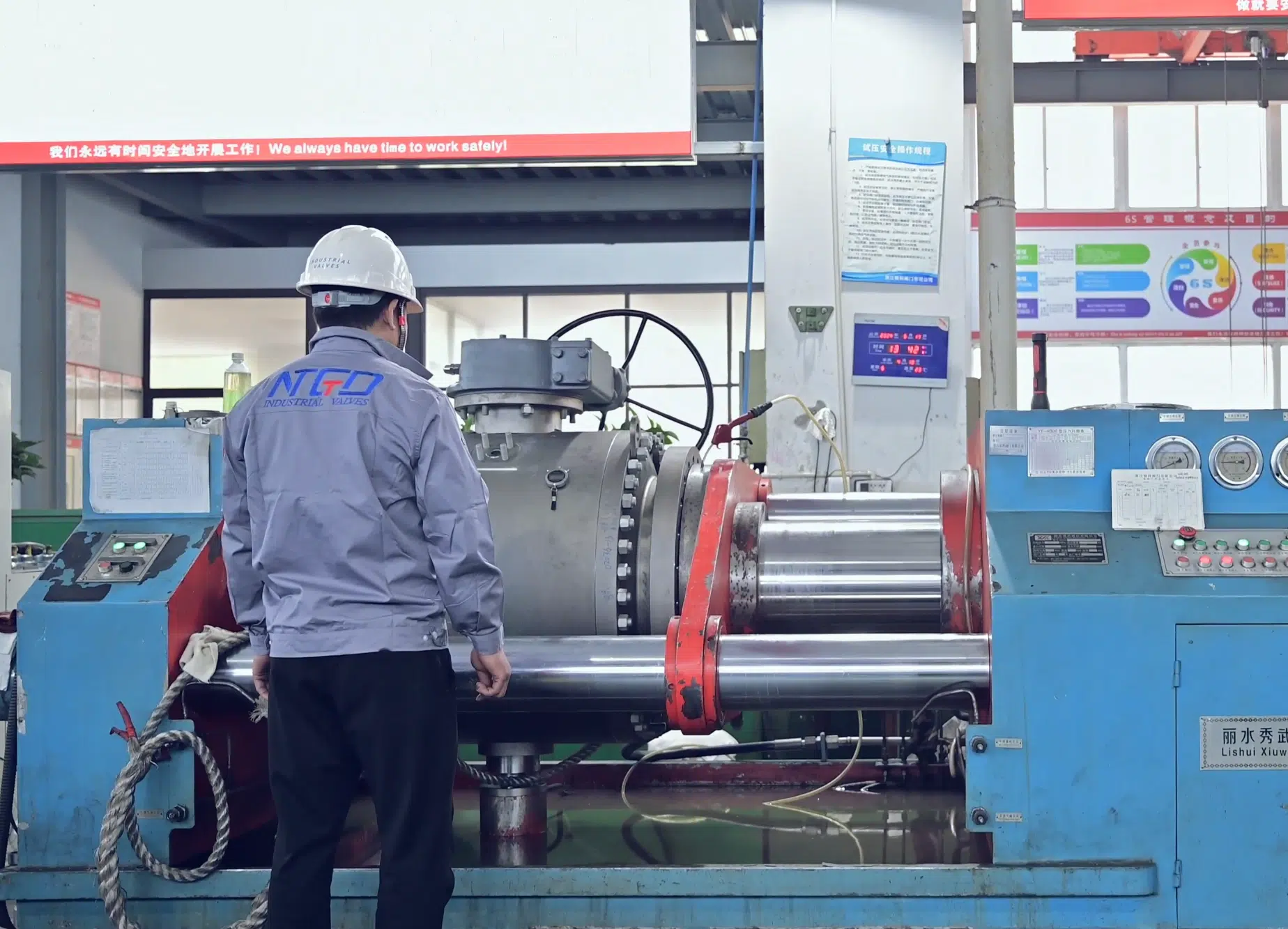
Sealing Test
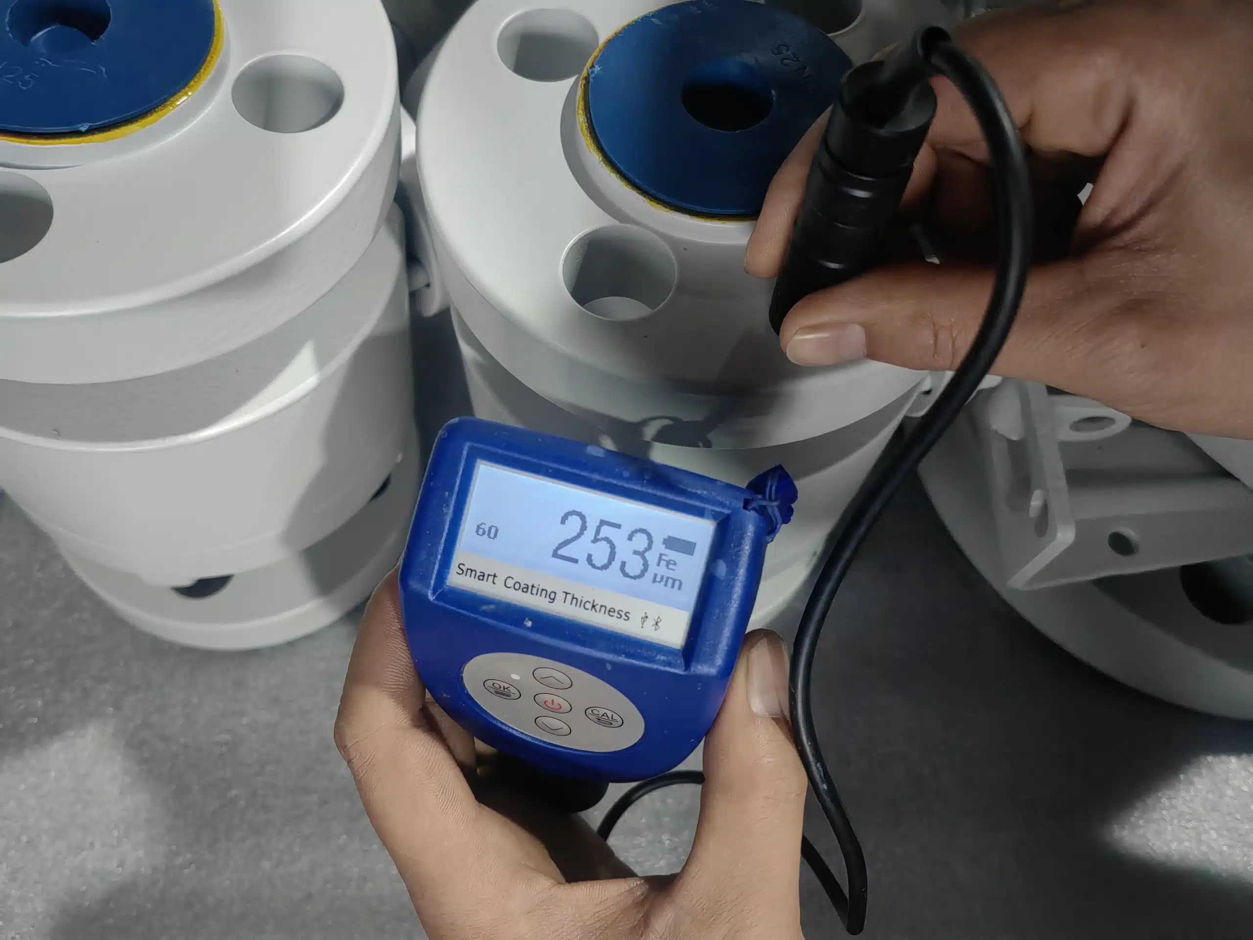
Painting Thickness Test

Low Emission Test

PT

Impact Test

Material Inspection