Steam Pressure Reducing Valve (PRV)
Sizing, Installation & Troubleshooting Guide (Hunting / Noise / Overpressure)
Steam pressure reducing valves (PRVs) do one mission-critical job in steam systems: reduce high inlet steam pressure to a stable, adjustable downstream pressure even when upstream pressure and load fluctuate.
According to guidance from the U.S. Department of Energy’s steam system best practices,
effective pressure management and condensate control are critical to maintaining steam system efficiency and preventing energy waste.
See the DOE Steam System Tools resource here:DOE Steam System Best Practices.
In real plants, most PRV “failures” do not start from pressure rating limits. They start from misapplication and station design errors, typically showing up as:
-
Hunting (downstream pressure oscillation)
-
Excessive noise (>85 dBA)
-
Trim erosion / short service life
-
Water hammer risk due to wet steam / condensate carryover
-
Downstream overpressure risk if protection strategy is missing or wrong
Above-the-Fold: Applications + Safety Note
For Steam Header Control • Process Stabilization • Turbine Makeup
A steam PRV stabilizes downstream pressure to protect equipment and maintain process performance across load changes.
Typical Applications
-
Steam header pressure segmentation (high → medium/low)
-
Process equipment stabilization (sterilizers, autoclaves, heaters)
-
Turbine exhaust make-up steam
-
Plant utility steam distribution
For complete steam system design, PRVs often operate alongside other steam components such as strainers and steam traps to ensure dry steam and stable pressure delivery. Explore our guides on steam distribution valves and condensate removal devices like steam traps and industrial strainers to build a complete steam station solution.
⚠ Critical Safety Note (High ΔP Reality)
PRVs often operate under large differential pressure (ΔP). Incorrect sizing or station layout can trigger:
-
Hunting (pressure cycling)
-
Noise & vibration (often a velocity/ΔP indicator)
-
Trim erosion and early leakage
-
Water hammer events
-
Downstream overpressure if protective devices are missing or misapplied
Correct selection + correct station layout = the real safety boundary.
✅ Get Free PRV Sizing & Layout Review
Email: [email protected] | WhatsApp: +86 138 6860 3320
PRV Station Layout (Recommended Diagram Placeholder)
Insert your original NTGD-branded station layout diagram here
Alt text suggestion: Steam pressure reducing valve station layout with strainer, drip leg and steam trap, pressure gauges, bypass line, sensing line location, and relief valve
Diagram should show (labels):
-
Upstream isolation valve
-
Strainer + blowdown
-
Drip leg + steam trap (to protect PRV from wet steam)
-
PRV
-
Upstream & downstream pressure gauges
-
Bypass valve (must close tight)
-
Sensing line tap location (for pilot/external pilot)
-
Downstream relief/safety strategy (project-dependent)
Quick Comparison: Direct-Acting vs Pilot-Operated vs Externally Piloted PRV
| PRV Type | Core Control Logic | Best Fit | Typical Control Behavior | Sensing Line | Key Risk if Misapplied |
|---|---|---|---|---|---|
| Direct-Acting | Spring acts directly on valve element | Small, point-of-use loads | More droop, narrower stable range | Usually none | Hunting at light load if oversized |
| Pilot-Operated (internal pilot/piston) | Pilot loads diaphragm/piston to move main valve | Headers & process duty | Wider range, better stability | Internal / sometimes external | Sensitive to dirt/orifice issues; needs stable sensing |
| Externally Piloted | External pilot improves feedback stability | Tight control duty | Fast response, tight regulation | External required | Wrong tap location = wrong control |
60-Second Selection Rules (Engineer Quick Pick)
Choose a steam PRV when:
-
Downstream pressure must stay stable while inlet pressure varies
-
Process equipment needs controlled steam pressure to avoid overheat/underheat
-
Steam header distribution needs pressure segmentation
-
You want self-contained control (no external power required)
Re-check selection if:
-
Minimum load is very low compared to maximum load (oversizing risk)
-
Return/backpressure conditions are high or unstable
-
Steam quality is poor (wet steam / condensate carryover)
-
Station cannot provide stable sensing conditions (no straight run)
Non-negotiable in real projects:
-
Define ΔP envelope and load range
-
Protect PRV with strainer + condensate removal
-
Confirm sensing location and bypass tight shut
-
Plan overpressure protection per project code/practice
Engineering Specifications
| Parameter | Typical Options | Field Meaning / Notes |
|---|---|---|
| Size range | DN15–DN300 (model dependent) | Do not size by line size alone—minimum load stability matters |
| Pressure class | ANSI 150–600 / PN16–PN100 | High ΔP = higher noise/erosion risk |
| Control architecture | direct / pilot / external pilot | Wide load swing → pilot/external pilot preferred |
| Trim options | standard / low-noise / multi-stage | High ΔP often benefits from staged trim / diffuser |
| Steam condition | saturated / superheated | Wet steam requires upstream drainage/separation strategy |
| Minimum controllable flow (concept) | Some designs use a minimum controllable fraction (e.g., 5% rated; larger sizes may be 10% typical) | If minimum load falls below minimum controllable flow → hunting risk increases |
| Straight pipe / sensing | For pilot/external pilot, tap should be in stable pressure zone | Put sensing tap in straight run, avoid elbows/tees turbulence |
| Strainer | Upstream recommended | Protects pilot/orifice/seat from debris |
| Noise target | Often engineered to ≤85 dBA (project dependent) | High ΔP may need diffuser / staged drop; insulation ≠ noise control |
NTGD steam PRVs are designed in accordance with internationally recognized valve standards such as
ASME B16.34,
which defines pressure–temperature ratings and design requirements for industrial valves used in high-pressure service.
What Is a Steam Pressure Reducing Valve?
A steam PRV is an automatic control valve that reduces high inlet steam pressure to a stable downstream pressure setpoint. It continuously modulates based on downstream feedback so the system sees consistent pressure even when demand changes.
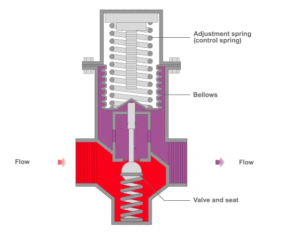
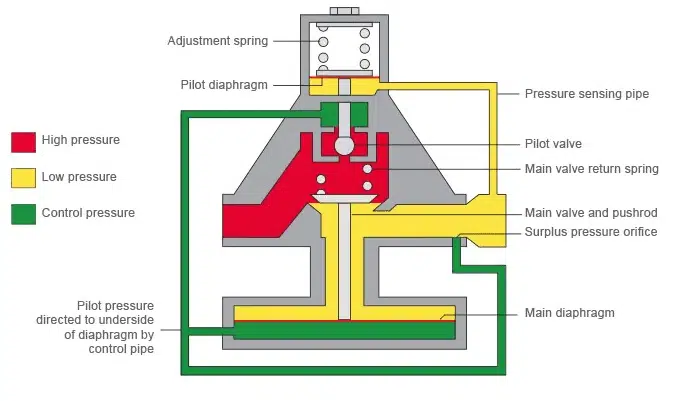
How Does a Steam PRV Work? (Working Principle)
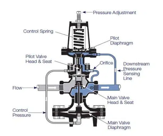
A PRV is a force-balance system:
-
Spring force / pilot setting establishes the desired outlet pressure
-
Downstream pressure feedback pushes against the setting force
-
The valve throttles until forces balance at setpoint
Why pilot-operated PRVs are common in industry
Pilot designs amplify control force and usually handle wide load ranges better—but only when:
-
pilot/orifice passages stay clean
-
sensing feedback is installed correctly
-
station layout avoids turbulence and wet steam carryover
Deep Engineering Concept 1
ΔP + Load Range = The Real Cause Behind “Hunting”
Hunting is downstream pressure oscillation (cycling). In the field, the #1 trigger is usually oversizing for minimum load.
Why oversizing causes hunting
At very low flow, the PRV operates near seat position. Tiny movement produces a relatively large flow change → the controller “overcorrects” → oscillation.
Most likely hunting root causes (ranked)
-
Minimum load below minimum controllable flow (oversized valve)
-
Bypass valve not fully tight shut (hidden parallel flow path)
-
Unstable sensing location (turbulence right after elbow/tee/reducer)
-
Pilot/orifice partially blocked (debris)
-
Rapid load swings without damping/station tuning
Practical meaning:
If the PRV hunts at light load but looks “OK” at higher load, suspect oversizing first.
Deep Engineering Concept 2
Noise (>85 dBA) = Velocity + ΔP + Trim Reality
Noise in PRVs is not just comfort—it’s a wear indicator.
What typically causes PRV noise
-
High outlet velocity under large ΔP
-
Undersized downstream piping
-
Single-stage pressure drop across trim
-
Wet steam carryover (erosion + instability)
What noise predicts
-
trim erosion → leakage spiral
-
vibration → station fatigue risk
-
shortened service life
Practical mitigation options
-
Increase downstream size where appropriate to reduce velocity
-
Use low-noise / multi-stage trim for high ΔP duty
-
Add a downstream noise diffuser/silencer (project dependent; typical noise reduction can be on the order of ~10–15 dBA depending on duty)
-
Ensure dry steam enters PRV (drainage/separation + trapping)
PRV Sizing Reality Check
Minimum Controllable Flow (The Fastest Way to Prevent Oversizing)
Many PRV issues happen because selection is made from line size or only maximum flow, ignoring minimum load behavior.
A practical field-safe rule is to check whether your minimum load falls below the PRV’s minimum controllable flow (often described as a percentage of rated capacity in many sizing guides).
-
Some references use ~5% of rated capacity as a practical lower boundary in many cases; larger valve sizes may behave closer to ~10%.
-
If your minimum load is below that boundary, hunting risk rises sharply.
This is exactly why “DN50 line → DN50 PRV” is one of the most common misapplications.
Accurate steam PRV sizing requires correct steam property data (density, absolute pressure, temperature).
When verifying Cv calculations or reviewing steam condition assumptions, refer to published steam property references such as
Engineering Toolbox – Steam Properties
to ensure thermodynamic values are consistent with operating conditions.
Sizing Example (Copy-Paste Friendly)
Given
-
Line: DN50
-
Inlet pressure: 0.5 MPaG
-
Required outlet pressure: 0.3 MPaG
-
Flow range: 60–500 kg/h (min to max)
Wrong selection pattern (common): choose DN50 PRV because the pipe is DN50.
Reality check:
If DN50 PRV’s practical minimum controllable flow is ~10% of rated, and the rated capacity (example) is 2000 kg/h, then:
-
Minimum controllable flow ≈ 2000 × 10% = 200 kg/h
-
But your minimum load = 60 kg/h (< 200 kg/h)
✅ Result: hunting is likely at low load.
Better solution options
-
Choose a smaller PRV size that keeps min load above minimum controllable boundary (if max load still fits)
-
Use parallel PRVs (small PRV for low load + main PRV for high load)
-
Use staged reduction or station damping where required by duty
Key takeaway:
Sizing is not only “can it pass max flow?” It is “can it control min flow stably?”
Installation & Commissioning (Step-by-Step)
1) Station Requirements (Non-negotiable)
-
Upstream isolation + downstream isolation
-
Upstream strainer (with blowdown preferred)
-
Drip leg + steam trap upstream to keep wet steam/condensate out of PRV
-
Pressure gauges before/after PRV
-
Bypass line (must close tight; verify during commissioning)
Before the PRV, install a steam strainer to prevent debris from entering the valve and pilot orifice.
2) Straight Pipe & Sensing Tap (Pilot/External Pilot)
For pilot/external pilot PRVs, sensing must read stable downstream pressure:
-
Put sensing tap on a straight run downstream
-
Avoid elbows/tees/reducers immediately after PRV
-
Keep sensing line clean and protected from blockage
3) How to Set Outlet Pressure (Pilot-Operated PRV)
-
Close bypass valve fully
-
Slowly open inlet isolation valve to pressurize station
-
Loosen pilot locknut
-
Turn adjusting screw clockwise to increase outlet pressure
-
Monitor downstream gauge until stable
-
Lock the setting and verify under operating load
4) Commissioning Checklist (Field-Safe)
-
Strainer installed and clean
-
Drip leg + trap draining properly
-
Bypass tight shut (no leakage)
-
Sensing line connected and unobstructed (if used)
-
Stable at minimum load and maximum load
-
No abnormal noise/vibration during load steps
PRV Station Safety Design
Overpressure Protection (Project-Dependent but Essential)
A PRV is a control device, not a guarantee against all abnormal scenarios. If a failure mode could lead to unsafe downstream conditions, your station design commonly includes a protection strategy such as:
-
safety/relief device downstream (setpoint per code/owner standard)
-
appropriate isolation and procedures
-
verification during commissioning and maintenance
Always follow local regulations and owner/industry standards for overpressure protection and safety devices.
For example, steam piping and pressure protection practices are commonly governed by codes such as
ASME B31.1 Power Piping,
which outlines requirements for pressure-reducing installations and downstream protection strategies.
Common PRV Problems & Solutions (Troubleshooting Table)
| Symptom | Most Likely Root Causes | Corrective Action (Field Order) | Prevention |
|---|---|---|---|
| Hunting / oscillation | Oversized for min load; bypass leakage; bad sensing location; pilot/orifice partially blocked | 1) Confirm bypass tight shut 2) Check strainer/orifice 3) Validate sensing tap 4) Re-check min controllable flow vs min load | Size for min-load stability; enforce station layout; maintain strainer |
| Excessive noise / vibration | High ΔP + velocity; no low-noise trim; downstream too small; wet steam carryover | 1) Verify ΔP & velocity risk 2) Ensure dry steam into PRV 3) staged trim/diffuser 4) adjust piping where possible | Plan noise control early; use staged drop; add diffuser if required |
| Low outlet pressure | Strainer clogged; inlet pressure insufficient; undersized valve; pilot mis-set | 1) Check inlet pressure 2) Blowdown/clean strainer 3) Re-adjust pilot 4) verify sizing | Complete RFQ inputs; maintenance schedule |
| Not opening | Orifice blocked; diaphragm failure; isolation closed; strainer blocked | 1) Confirm isolation open 2) Clean strainer/orifice 3) inspect diaphragm/pilot | Strainer; clean steam; commissioning checklist |
| Not closing / overpressure | Bypass open/leaking; sensing failure; debris on seat; pilot stuck | 1) Close bypass 2) clean seat/pilot 3) verify sensing line 4) confirm protection strategy | Bypass QA; filtration; correct sensing; safety device plan |
Additionally, verify that isolation and control valves upstream such as Rising Stem Ball Valves or Top Entry Ball Valves are operating correctly, as worn seats or improper positioning can mimic PRV control issues.
Field Test
Fast Diagnostic Decision Tree
-
Check bypass valve tight shut
Even a small leak can mimic PRV instability. -
Check strainer condition / blowdown
Blockage causes low outlet pressure and unstable pilot behavior. -
Verify sensing line integrity (pilot/external pilot)
Wrong tap location or plugged line = wrong feedback = wrong control. -
Evaluate min-load stability
If it only hunts at light load, oversizing is highly likely.
This order prevents misdiagnosis and unnecessary valve replacement.
Field Application Case Studies
Case 1 — Hunting Caused by Oversizing + Low Minimum Load
Duty: Steam tracing station, seasonal load change
Operating condition: Inlet pressure 0.8 MPaG → required outlet pressure 0.3 MPaG, load variation 60–400 kg/h.
Symptom: Downstream pressure cycles at night/light load; operators blame PRV
Finding: Minimum load far below PRV’s practical minimum controllable boundary; bypass valve also had micro-leakage
Fix: Tight shut bypass + install smaller parallel PRV for low-load range
Result: Stable downstream pressure maintained within ±3% of setpoint across seasonal load variation; hunting eliminated during light-load periods.
Case 2 — Noise & Early Trim Wear Under High ΔP
Duty: Header reduction with large ΔP
Operating condition: Inlet pressure 1.2 MPaG → outlet 0.4 MPaG, continuous duty with high differential pressure.
Symptom: Noise >85 dBA and vibration; early trim erosion signs
Finding: Single-stage pressure drop + high outlet velocity
Fix: Low-noise / staged trim + downstream diffuser option evaluated; improve upstream drainage to keep wet steam out
Result: Noise reduced from approximately 92 dBA to below 80 dBA (site measurement), station vibration reduced, trim service life extended from less than 12 months to over 24 months.
Maintenance & Service Schedule
-
Daily/Shift check: inlet/outlet pressure stability, abnormal noise, external leakage
-
Monthly: blowdown strainer, check gauges, verify bypass shutoff, check sensing line integrity
-
Annual/Overhaul (duty dependent): inspect seat/trim, pilot/orifice, diaphragm/piston; replace wear parts kit
Why Choose NTGD
Authored by: NTGD Steam System Engineering Team
Last Updated: 2026-03
NTGD supplies industrial steam PRVs engineered for demanding steam header and process control applications. Our engineering team supports:
-
PRV sizing review (minimum / normal / maximum load verification)
-
Station layout review (sensing location, straight pipe, bypass, drainage)
-
High ΔP noise mitigation strategy (staged trim / diffuser options)
-
Troubleshooting guidance for hunting and instability issues
All NTGD steam PRVs are manufactured under ISO 9001 quality management systems and are designed in accordance with internationally recognized standards such as ASME B16.34 for pressure–temperature ratings.
Documentation available upon request:
-
MTC (Material Test Certificates)
-
Inspection & Test Reports
-
Pressure test records
-
Dimensional inspection records
In critical steam service, engineering support matters as much as hardware selection.
RFQ Checklist
-
Inlet pressure (min/normal/max)
-
Required outlet pressure setpoint
-
Steam flow range (min/normal/max)
-
Steam condition (saturated/superheated, wet steam risk)
-
Line sizes + available straight run lengths
-
Noise requirement (if any)
-
Downstream constraints (backpressure, tie-ins)
✅ Request a Free Quote & Sizing Support
Email: [email protected] | WhatsApp: +86 138 6860 3320
Explore Related Pages
-
Steam Trap Overview (Hub): https://ntgdvalve.com/steam-trap/
-
Thermodynamic Steam Trap: https://ntgdvalve.com/thermodynamic-steam-trap/
-
Inverted Bucket Steam Trap: https://ntgdvalve.com/inverted-bucket-steam-trap/
FAQ
1️⃣ How do you set the pressure on a pilot-operated steam PRV?
Close bypass, open inlet slowly, turn pilot adjusting screw clockwise to increase outlet pressure, verify under load, then lock the setting.
2️⃣ Why does a steam PRV hunt (pressure oscillation)?
Most commonly because the PRV is oversized for minimum load. Other causes include bypass leakage, unstable sensing location, or pilot/orifice blockage.
3️⃣ Why is my steam PRV noisy?
High ΔP and high velocity are typical causes. Solutions include staged/low-noise trim, downstream diffuser options, and ensuring dry steam enters the PRV.
4️⃣ Direct-acting vs pilot-operated PRV — which should I choose?
Direct-acting is suitable for small, stable loads. Pilot-operated or externally piloted designs are preferred for wider load ranges and tighter pressure control.
5️⃣ Do I need overpressure protection after a steam PRV?
If a failure could cause unsafe downstream conditions, the station design typically includes an overpressure protection strategy per local code and owner standards.
6️⃣ What information do you need to size and quote a steam PRV?
Inlet pressure range, outlet setpoint, flow range (min/normal/max), steam condition, pipe sizes, available straight run length, and any noise limits.
7️⃣ Can a steam PRV be used for superheated steam?
Yes, but material selection and trim design must match temperature conditions. Superheated steam may require upgraded trim materials and sealing components.
8️⃣ What is the typical service life of a steam PRV?
Service life depends on ΔP, steam quality, and maintenance. In well-designed stations with proper filtration and drainage, trim life often exceeds 2–3 years in continuous service.
9️⃣ How often should a steam PRV be serviced?
Routine visual checks should be performed regularly. Strainer blowdown is typically monthly, while full inspection intervals depend on duty severity—often annually for critical service.
🔟 What causes downstream overpressure after a PRV?
Common causes include bypass valve leakage, pilot failure, sensing line blockage, debris on the seat, or missing downstream protection strategy.