Name des Autors: Bruce Zheng
Rolle des Autors: Mitbegründer und Ventilingenieur bei NTGD Valve
Autor Bio: Bruce Zheng ist Mitbegründer und Ventilingenieur bei NTGD Valve und konzentriert sich auf die Auswahl von Industrieventilen, Anwendungen und technische Inhalte für globale B2B-Einkäufer.
Zuletzt aktualisiert: Mai 28, 2026
An adjusting pressure reducing valve is a pressure control valve used to reduce a higher inlet pressure to a lower, more stable downstream pressure. The term “adjusting” is critical here because the valve is not only installed to reduce pressure once; it also includes an adjustment mechanism that allows the outlet pressure setting to be changed within the valve’s design range. For industrial users, this means the valve must be evaluated both as a pressure reducing product and as an adjustable pressure-setting device.
In most designs, pressure setting is controlled through an adjustment screw, spring, diaphragm, piston, or pilot system. When the adjustment mechanism changes spring compression or pilot setpoint, the valve changes how it opens, throttles, or closes in response to downstream pressure. This is why pressure reducing valve adjustment must be treated as a controlled pressure-setting process, not as a simple screw-turning action.
This article explains what an adjusting pressure reducing valve is, how it works, which components affect pressure setting, how direct-acting and pilot-operated designs differ, where these valves are used, how pressure adjustment is generally handled, and how common adjustment-related problems are diagnosed.
In this article, PRV refers to a pressure reducing valve unless otherwise stated; broader terminology and selection context are covered in NTGD’s industrial PRV valve guide. A pressure reducing valve is different from a pressure relief valve, and the adjustment logic for the two valve types should not be treated as the same.
What Is an Adjusting Pressure Reducing Valve?
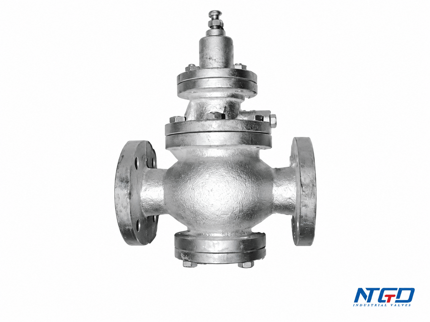
An adjusting pressure reducing valve is designed to control downstream pressure by reducing higher upstream pressure to a lower pressure required by the system. It is commonly used where downstream equipment, instruments, pipelines, or process units need a stable pressure level instead of the full supply pressure.
The valve normally works by balancing spring force, diaphragm or piston force, and downstream pressure. When the downstream pressure falls below the setting, the valve opens or remains open enough to allow flow. When downstream pressure rises toward or above the setpoint, the valve reduces the opening to help prevent excessive outlet pressure.
The adjustment feature allows the operator or maintenance team to change the outlet pressure setting, usually through an adjustment screw, handle, pilot set screw, or similar mechanism. The exact adjustment method depends on the valve design.
An adjusting pressure reducing valve is therefore both:
- a pressure reducing device, because it lowers inlet pressure to a controlled outlet pressure;
- an adjustable pressure control device, because the outlet pressure setting can be changed within a defined range.
The adjustment should always be verified by outlet pressure readings, not by screw position alone. The final setting depends on system design, valve construction, spring range, inlet pressure, flow demand, media, temperature, and the manufacturer’s instructions.
The adjustable pressure range of the valve is limited by its design, installed spring range, pressure class, available inlet pressure, and manufacturer specifications. It should not be adjusted beyond the rated range of the valve.
How an Adjusting Pressure Reducing Valve Works
An adjusting pressure reducing valve works by responding to downstream pressure. The internal mechanism compares the outlet pressure with a mechanical or pilot-controlled force. When these forces are balanced, the valve maintains the reduced pressure near the required setting.
The exact internal arrangement can differ by manufacturer and valve type, but most adjusting pressure reducing valves use the same basic control idea: the valve opening changes according to downstream pressure feedback.
Spring Force and Downstream Pressure Balance
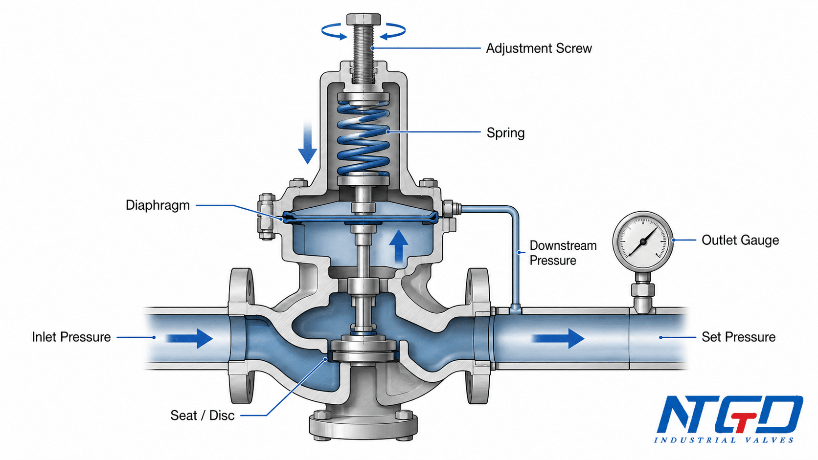
In a direct-acting design, the adjustment screw usually changes spring compression. The spring applies force to a diaphragm or piston. Downstream pressure pushes back against the diaphragm or piston in the opposite direction.
When the downstream pressure is too low, spring force helps keep the valve open so flow can continue. As downstream pressure increases, pressure acting on the diaphragm or piston pushes against the spring force and reduces the valve opening. This helps maintain a lower, controlled outlet pressure.
The balance can be simplified as:
| Control Element | Role in Pressure Control |
|---|---|
| Upstream pressure | Provides the supply pressure entering the valve. |
| Downstream pressure | Acts as the controlled pressure signal. |
| Feder zum Einstellen | Provides the force used to set the desired outlet pressure. |
| Diaphragma oder Kolben | Responds to pressure and transfers force to the valve mechanism. |
| Seat and disc / plug | Control the flow opening inside the valve. |
| Justierschraube | Changes spring compression or setpoint. |
This force balance is also why adjustment response depends on valve condition and system demand. If the spring, diaphragm, seat, pilot path, or downstream pressure signal cannot respond correctly, turning the adjustment screw alone will not produce stable outlet pressure.
This is why pressure reducing valve setting should be confirmed by pressure gauge readings. A change in screw position does not automatically prove that the controlled pressure has changed correctly.
How the Adjustment Screw Changes the Set Pressure
The adjustment screw is one of the most important parts of an adjusting pressure reducing valve. In many spring-loaded designs, turning the adjustment screw changes spring compression. More spring compression usually raises the downstream pressure setting, while less compression usually lowers it.
However, this direction is not universal for every valve design. Some pilot-operated designs, cartridge-style regulators, or special configurations may use a different adjustment arrangement. The valve datasheet or manufacturer’s installation, operation, and maintenance instructions should always be checked before adjustment.
The adjustment screw does not directly “make pressure.” It changes the force balance inside the valve. The actual outlet pressure still depends on:
- inlet pressure;
- required downstream pressure;
- flow demand;
- spring range;
- diaphragm or piston condition;
- pilot valve condition if used;
- valve sizing;
- internal cleanliness;
- media behavior.
If the outlet pressure does not respond after the screw is turned, that is usually a troubleshooting signal. It may indicate blocked passages, insufficient inlet pressure, diaphragm damage, pilot line problems, wrong spring range, or internal wear.
Why Gauge-Based Pressure Confirmation Matters
An adjusting pressure reducing valve should be checked with pressure gauges, especially on the downstream side. Without an outlet pressure reading, the operator cannot confirm whether the adjustment actually achieved the required set pressure.
For industrial service, it is often useful to check both inlet and outlet pressure. This helps separate valve adjustment problems from supply pressure problems. For example, a low outlet pressure may not be caused by a low setting if the inlet pressure is already too low or the upstream strainer is blocked.
The adjustment process should therefore be based on pressure readings, not on screw turns, sound, flow feel, or visual position.
Adjusting without a pressure gauge can lead to excessive downstream pressure, insufficient process pressure, leakage, water hammer, equipment damage, or unsafe operating conditions, especially in high-pressure or critical services.
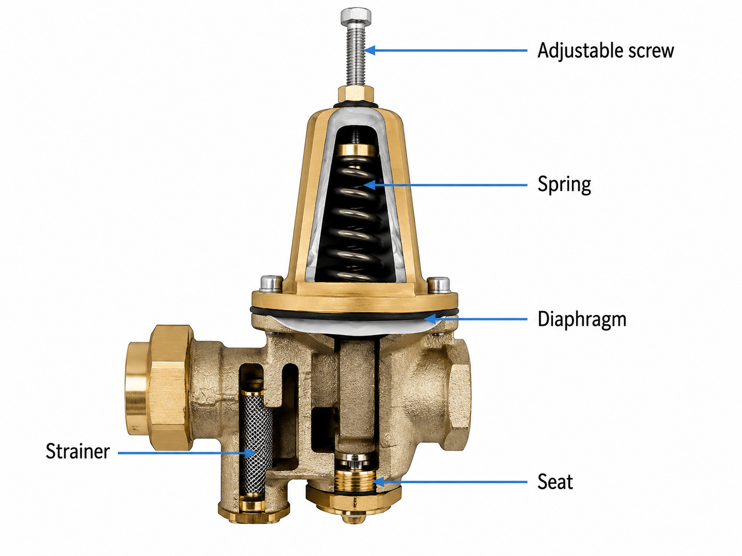
Main Components of an Adjusting Pressure Reducing Valve
The components of an adjusting pressure reducing valve should not be treated as a disconnected parts list. Each important component has a role in pressure control, pressure setting, sealing, or troubleshooting.
| Komponente | Function in Pressure Control | Adjustment / Troubleshooting Relevance |
|---|---|---|
| Ventilkörper | Contains the internal flow passage and pressure boundary. | Material, pressure class, and body design affect service suitability. |
| Adjustment screw or handle | Changes spring compression or pilot setpoint. | Key part for pressure reducing valve adjustment. |
| Frühling | Provides adjustable force against the diaphragm or piston. | Wrong spring range or spring damage can prevent correct setting. |
| Diaphragma oder Kolben | Responds to downstream pressure and transfers force. | Damage can cause unstable pressure or no response. |
| Seat and disc / plug | Control the internal flow opening. | Dirt, wear, or damage can cause leakage, overshoot, or poor shutoff. |
| Gaskets and sealing parts | Help prevent external leakage at joints. | Leakage around bonnet or adjustment area requires inspection. |
| Steuerventil | Controls the main valve in pilot-operated designs. | Pilot blockage, wrong pilot setting, or trapped air can affect control. |
| Strainer or filter element, if installed | Helps reduce debris entering sensitive passages. | Blockage can cause low outlet pressure or delayed response. |
Valve Body and Flow Passage
The valve body forms the pressure-retaining structure of the valve. It contains the inlet and outlet ports, internal flow passage, seat area, and connection ends. The body must be suitable for the media, pressure class, temperature, and connection type required by the system.
For an adjusting pressure reducing valve, the body is not only a housing. Its internal flow path and seat arrangement affect how the valve reduces pressure and responds to changing demand.
Adjustment Screw or Handle
The adjustment screw or handle is the visible adjustment point on many pressure reducing valves. In smaller or simpler designs, the operator may turn a screw or handle to compress or release the spring. In pilot-operated designs, the adjustment point may be on the pilot valve rather than directly on the main valve.
The adjustment screw should be moved gradually. Large or fast changes can cause overshoot, unstable pressure, or confusion during troubleshooting. The final outlet pressure must be verified with a downstream gauge.
The adjustment screw should therefore be treated as a set-pressure control point, not as a manual open-close device. Any screw movement must be checked against the actual downstream pressure response.
Spring and Diaphragm
The spring and diaphragm are central to the force balance inside many adjusting pressure reducing valves. The spring creates the adjustable force. The diaphragm senses downstream pressure and moves in response to pressure changes.
If the diaphragm is damaged, if the spring is outside the correct range, or if the pressure sensing path is blocked, the valve may not respond correctly to adjustment.
This is why an adjustment problem is not always an operator problem. It may be a component condition problem.
Seat, Disc and Sealing Parts
The seat and disc, plug, or main valve head control the internal opening through which the fluid passes. If dirt or foreign material is trapped near the seat, the valve may not close properly. If the seat or disc is worn, the outlet pressure may creep upward or fail to stabilize.
Gaskets and sealing parts help prevent external leakage. Leakage near the adjustment area, bonnet, pilot fittings, or body joint should not be solved by simply tightening the adjustment screw. It should be treated as a sealing or maintenance issue.
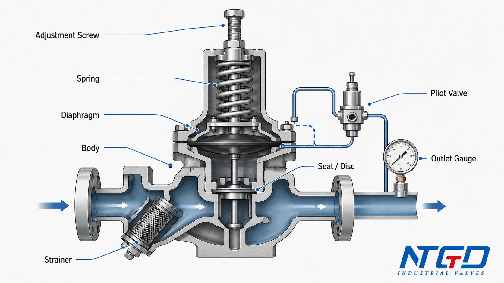
Pilot Valve for Pilot-Operated Designs
A pilot valve is used in pilot-operated adjusting pressure reducing valves. The pilot controls pressure signals to the main valve and allows the main valve to handle larger flow changes with improved control compared with many direct-acting designs.
Because the pilot system is part of the control loop, pilot valve adjustment, pilot strainer blockage, trapped air, blocked sensing lines, or pilot diaphragm damage can all affect downstream pressure. Pilot-operated valves therefore require careful pressure confirmation and stabilization time after adjustment.
Direct-Acting vs Pilot-Operated Adjusting Pressure Reducing Valves
Adjusting pressure reducing valves are commonly grouped into direct-acting and pilot-operated designs. Both are used to reduce and control downstream pressure, but their adjustment behavior and troubleshooting focus are different.
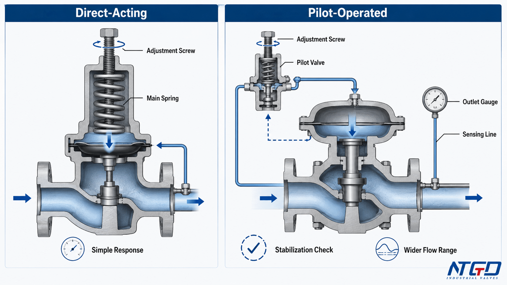
Direct-Acting Adjusting Pressure Reducing Valves
A direct-acting adjusting pressure reducing valve uses the main spring and diaphragm or piston to respond directly to downstream pressure. The adjustment screw changes spring compression, which changes the pressure setting.
Direct-acting designs are often selected for smaller loads, local pressure reduction points, or services where moderate pressure control is acceptable. They are usually simpler and have fewer pilot components.
Their main advantage is simplicity. Their limitation is that outlet pressure may vary more under changing flow demand compared with pilot-operated designs. The exact performance depends on the valve design, spring range, flow condition, and service conditions.
Pilot-Operated Adjusting Pressure Reducing Valves
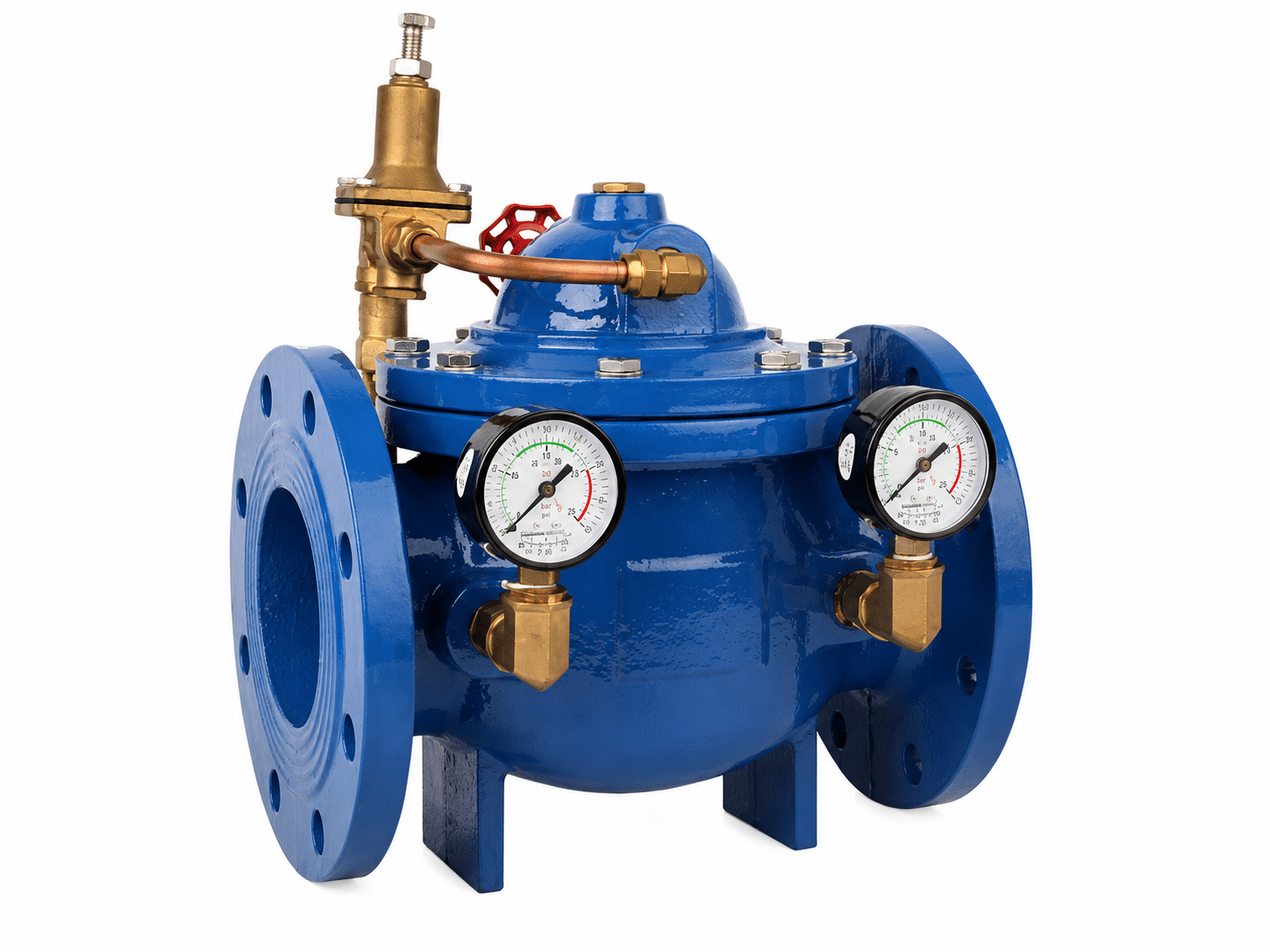
A pilot-operated adjusting pressure reducing valve uses a pilot valve to control the main valve. The pilot senses downstream pressure and regulates the pressure acting on the main diaphragm or piston. This allows the main valve to respond to larger flow changes or more demanding pressure control conditions.
Pilot-operated designs are often used where flow range is wider, pressure control needs to be more stable, or larger line sizes are involved. Their advantage is control capability. Their limitation is that the pilot circuit adds more components that must remain clean, correctly adjusted, and properly connected.
If a pilot-operated valve does not respond to adjustment, the cause may be in the pilot valve, sensing line, pilot strainer, trapped air, or main diaphragm rather than only in the adjustment screw.
Key Adjustment Differences
| Faktor | Direct-Acting Design | Pilot-Operated Design |
|---|---|---|
| Pressure control method | Main spring and diaphragm / piston respond directly to downstream pressure. | Pilot valve controls the signal acting on the main valve. |
| Main adjustment point | Main spring or adjustment screw. | Pilot set screw or pilot control system. |
| Response behavior | Simpler and more direct response. | Better suited to larger or wider flow demand when correctly sized and maintained. |
| Pressure control stability | Usually more affected by flow changes and spring range. | Usually better suited to wider flow changes when correctly sized and maintained. |
| Typical service fit | Smaller loads, local pressure reduction, point-of-use service. | Larger flow ranges, larger systems, or tighter control requirements. |
| Common adjustment concern | Spring range, diaphragm condition, seat condition. | Pilot strainer, sensing line, pilot diaphragm, trapped air, stabilization. |
| Schwerpunkt Wartung | Main valve internals and spring/diaphragm condition. | Pilot system plus main valve condition. |
| Begrenzung | May show wider pressure variation under changing demand. | More components can affect response and troubleshooting. |
Industry guidance on direct and pilot-operated regulators also treats manufacturer-specific instructions as necessary, so actual control accuracy should be confirmed from the valve datasheet or manufacturer specification.
For selection and troubleshooting, the practical difference is this: direct-acting designs are simpler and easier to inspect, while pilot-operated designs can offer better control over wider flow changes but require closer attention to pilot condition, sensing line condition, and stabilization after adjustment.
The correct design depends on media, pressure range, flow demand, response requirement, maintenance access, and the required downstream pressure stability. A direct-acting design is not automatically “better” because it is simpler, and a pilot-operated design is not automatically “better” because it is more advanced. The system requirement should decide the design.
Pressure Setting and Adjustment Method
Pressure setting and adjustment are important support functions for an adjusting pressure reducing valve. The adjustment process should confirm that the valve can maintain the required downstream pressure under the relevant operating condition.
This section gives a general adjustment logic. It should not replace the actual valve datasheet, manufacturer IOM, project specification, or site safety procedure.
Before Adjusting the Valve Setting
Before adjusting the valve, confirm that adjustment is actually the right action. Many pressure problems are caused by conditions that cannot be corrected by turning the adjustment screw.
Before adjustment, check:
- required downstream pressure;
- current downstream pressure;
- inlet pressure;
- normal flow condition;
- media and temperature;
- whether the valve is direct-acting or pilot-operated;
- whether the installed spring range is suitable;
- whether the valve size matches the actual load;
- whether strainers, pilot lines, or sensing lines may be blocked;
- whether there is visible leakage, corrosion, vibration, or damage.
The required downstream pressure should come from system design, equipment requirements, project specification, valve datasheet, or process requirement. It should not be copied from a residential water pressure recommendation or another unrelated system.
These checks determine whether the next action should be adjustment, inspection, cleaning, sizing review, or replacement planning. If the basic pressure and condition checks do not support adjustment, turning the screw may only hide the real fault.
Adjustment Screw, Locknut, Spring and Diaphragm Logic
In many pressure reducing valves, the adjustment screw is secured by a locknut or jam nut. The locknut prevents the setting from drifting due to vibration, handling, or pressure fluctuation.
In a typical adjustment sequence, the locknut is loosened first, the adjustment screw is moved gradually, the downstream gauge is observed after each change, and the locknut is tightened again only after the required outlet pressure is confirmed. The detailed operating sequence should remain in the adjustment step table below.
In many designs, turning the adjustment screw clockwise increases spring compression and raises the downstream pressure setting. Turning it counterclockwise reduces spring compression and lowers the setting. However, this direction must be verified against the actual valve design because not all valves are built the same way.
The pressure reducing valve adjustment screw should not be forced to its limit. If outlet pressure does not change after adjustment, stop and inspect the system instead of continuing to turn the screw.
General Pressure Reducing Valve Adjustment Steps
Whenever possible, adjustment should be checked under the system’s normal operating flow condition. Pressure readings taken at no-load or unusually low-flow conditions may not reflect actual performance under normal demand.
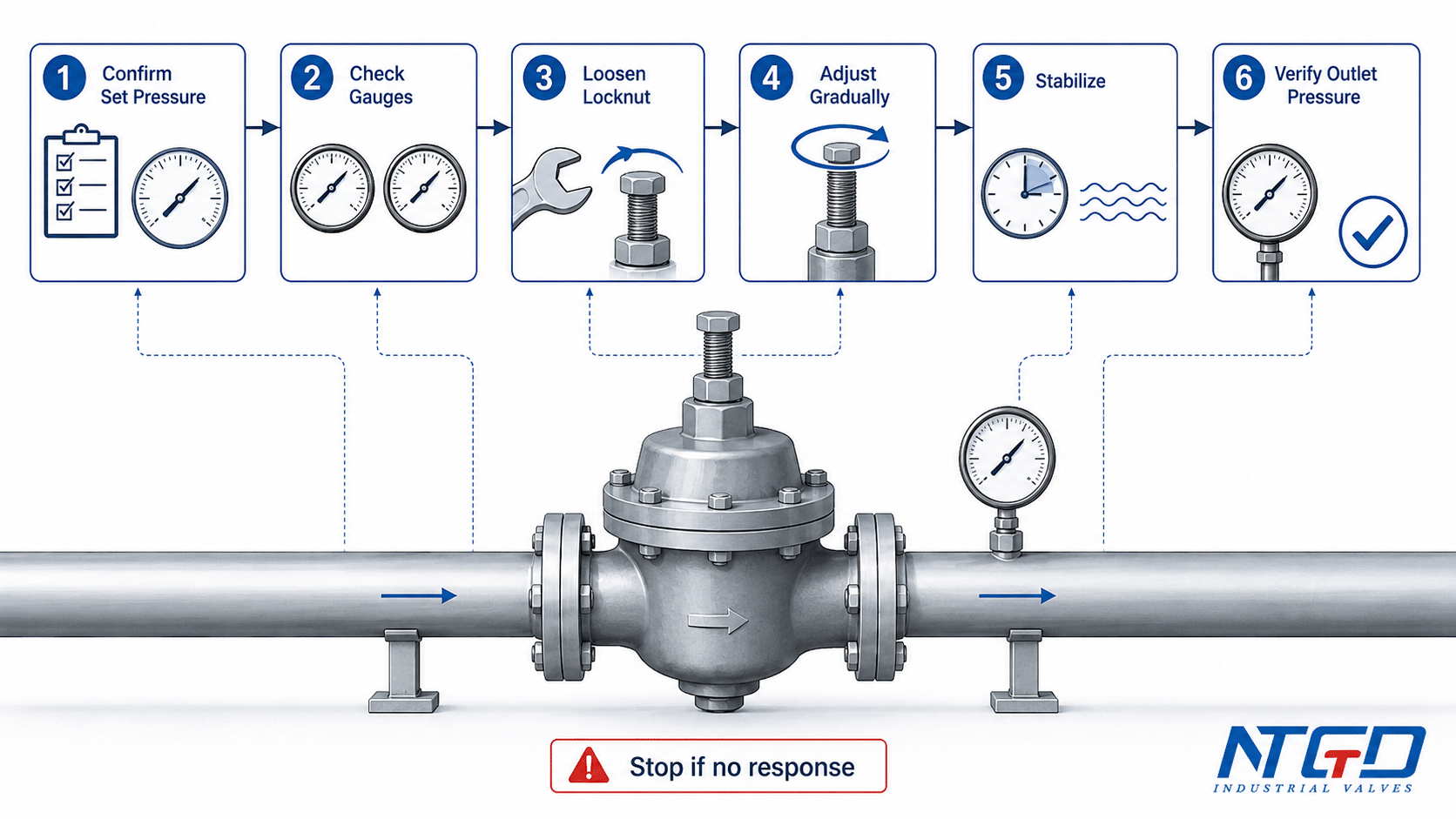
| Schritt | Was zu tun ist | Warum es wichtig ist |
|---|---|---|
| 1 | Confirm the required downstream pressure. | The target pressure must come from the system requirement, not guesswork. |
| 2 | Check inlet and outlet pressure readings. | This confirms whether the supply pressure is sufficient and whether the valve is controlling. |
| 3 | Confirm valve and system condition. | Blockage, wrong sizing, leakage, or diaphragm damage may make adjustment ineffective. |
| 4 | Loosen the locknut or jam nut. | This allows the adjustment screw to be moved without damaging the locking arrangement. |
| 5 | Turn the adjustment screw gradually. | Small changes reduce the risk of overshoot or unstable pressure. |
| 6 | Allow the valve and system to stabilize. | Pilot-operated valves and larger systems may need time before pressure settles. |
| 7 | Recheck downstream pressure. | The gauge reading confirms the actual controlled pressure. |
| 8 | Secure the setting. | Tightening the locknut helps prevent setting drift. |
| 9 | Monitor under operating condition. | Pressure may change when flow demand or load condition changes. |
If the outlet pressure does not change after controlled adjustment, do not keep turning the screw. Treat the no-response condition as a signal to inspect the valve, pilot circuit, upstream strainer, sensing line, spring range, diaphragm, and system supply pressure.
This process supports common searches such as how to adjust pressure reducing valve, PRV adjustment, and pressure reducer adjustment. However, the actual site procedure should always follow the specific valve design and manufacturer instructions.
How to Confirm Downstream Pressure After Adjustment
The adjustment is complete only when the downstream pressure is confirmed, stable, and suitable for the system. Do not use the number of screw turns as the final confirmation.
A proper confirmation should include:
- outlet pressure after adjustment;
- inlet pressure during adjustment;
- flow condition during the check;
- response time after adjustment;
- whether the valve hunts, overshoots, or drifts;
- whether the locknut tightening changed the setting;
- whether the pressure remains acceptable under normal demand.
If the pressure does not stabilize, review valve sizing and selection criteria, spring range, pilot circuit condition, strainer blockage, downstream demand variation, or internal wear.
When Adjustment Does Not Solve the Problem
When adjustment does not change outlet pressure, or when pressure remains unstable after controlled adjustment, the next step is inspection rather than continued screw movement.
Pressure reducing valve adjustment should be stopped and reviewed more carefully when:
- the outlet pressure does not respond to adjustment;
- the required downstream pressure is close to system limits;
- the valve is in steam, gas, oxygen, hydraulic, or critical process service;
- the valve is pilot-operated and pressure is hunting or overshooting;
- the valve has repeated setting drift;
- the installed valve may be undersized or oversized;
- the diaphragm, seat, pilot valve, or spring may be damaged;
- leakage is visible around the adjustment area.
In these cases, continued adjustment may make the problem worse. The correct action may be inspection, cleaning, sizing review, repair, or replacement.
Applications of Adjusting Pressure Reducing Valves
Adjusting pressure reducing valves are used where downstream pressure must be reduced, controlled, or protected from excessive supply pressure. The exact valve design and adjustment procedure depend on the media and system requirement.
| Anwendungsbereich | Why Pressure Reduction Is Needed | Adjustment / Selection Note |
|---|---|---|
| Water distribution and supply systems | Helps reduce higher supply pressure to a controlled downstream pressure. | Water-specific adjustment should follow the Wasserdruckreduzierventil design and site requirements. |
| Dampf-Service | Helps deliver steam at a lower pressure for equipment or process use. | Steam PRVs require attention to temperature, condensate behavior, and warm-up conditions. |
| Compressed air and gas systems | Helps protect downstream equipment from excessive pressure. | Material, sealing, and safety requirements must match the gas service. |
| Hydraulic systems | Helps control pressure to actuators, presses, or branch circuits. | Hydraulic adjustment may involve different response and safety requirements. |
| Industrial process pipelines | Helps stabilize pressure before equipment, instruments, or process units. | Valve sizing and flow range should be reviewed before setting changes. |
| Equipment inlet pressure protection | Helps reduce the risk of damage caused by excessive inlet pressure. | The required downstream pressure should come from equipment specifications. |
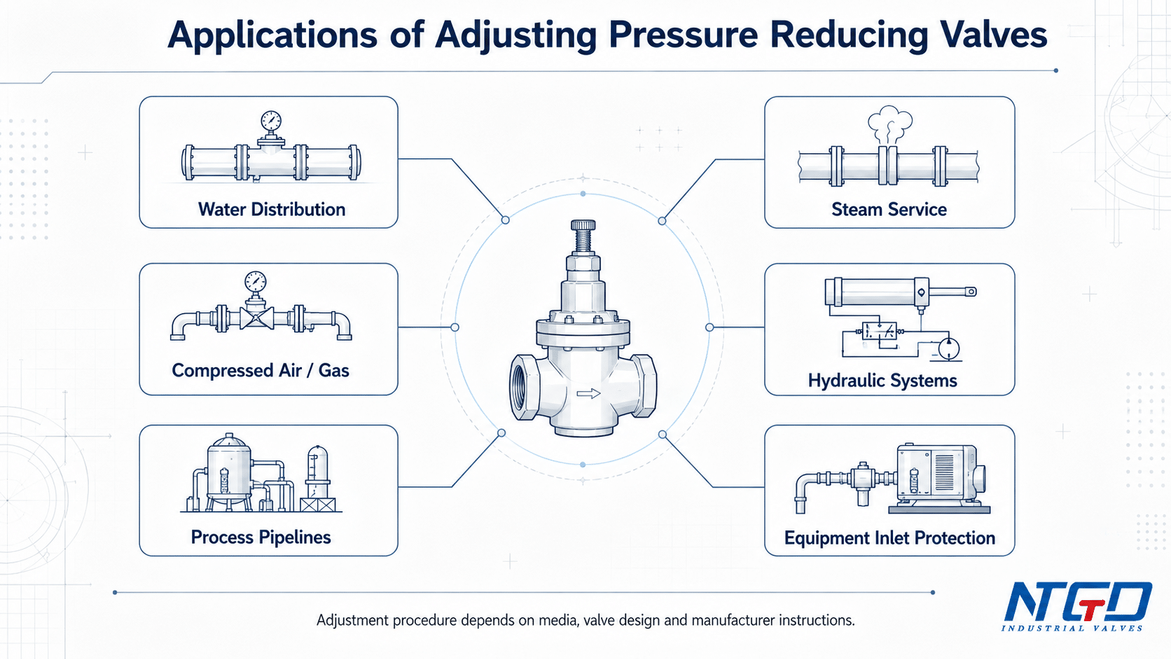
These applications share the same pressure-reduction principle, but the adjustment procedure should still follow the specific valve type, medium, temperature, safety requirement, and manufacturer documentation for that service.
These application categories do not mean one adjustment procedure applies to all services. Water, steam, gas, hydraulic, and process systems can have different installation requirements, safety procedures, and maintenance needs.
For that reason, the current article explains general adjustment and product-support logic for adjusting pressure reducing valves. Service-specific pages or datasheets should be used when the application requires a more specific procedure.
Advantages and Limitations of Adjusting Pressure Reducing Valves
An adjusting pressure reducing valve can provide strong system value when selected, installed, and adjusted correctly. At the same time, adjustment has limits. It cannot correct every pressure problem.
| Benefit / Limitation | Engineering Meaning | Buyer / Maintenance Note |
|---|---|---|
| Helps maintain downstream pressure | Reduces higher inlet pressure to a controlled outlet pressure. | Confirm the required set pressure before selection or adjustment. |
| Protects downstream equipment | Helps prevent excessive pressure from reaching sensitive equipment. | Check downstream equipment pressure limits. |
| Supports different pressure control needs | Direct-acting and pilot-operated designs can suit different flow and control requirements. | Select design type according to flow range, pressure stability, and maintenance access. |
| Allows field pressure setting within design limits | The adjustment mechanism allows outlet pressure to be tuned within the rated range of the valve. | Do not exceed spring range or manufacturer instructions. |
| Supports troubleshooting | Pressure response can help identify sizing, blockage, diaphragm, or pilot issues. | No response after adjustment means inspection is needed. |
| Requires gauge-based verification | Pressure setting must be verified by calibrated pressure instruments to confirm accuracy and safety. | Screw turns alone are not a reliable setting method. |
| Cannot fix wrong sizing | An undersized or oversized valve may remain unstable even after adjustment. An oversized valve may hunt or cause unstable control, while an undersized valve may fail to deliver the required downstream pressure under normal flow demand. | Review flow range and valve capacity. |
| Cannot repair internal damage | Damaged diaphragm, worn seat, blocked pilot line, or broken spring may prevent control. | Maintenance or replacement may be needed. |
| Service-specific behavior differs | Water, steam, gas, and hydraulic systems behave differently. | Do not apply one generic setting procedure to every medium. |
| Larger or pilot-operated designs may need more space and maintenance attention | More components can improve control but also add inspection points. | Consider installation space, access, and maintenance plan. |
The main advantage of an adjusting pressure reducing valve is not simply that it can be turned or adjusted. Its value is that it allows controlled downstream pressure when the valve design, spring range, media compatibility, and system conditions are suitable.
Incorrect adjustment can lead to unstable outlet pressure, repeated troubleshooting, unnecessary valve replacement, or downstream equipment risk. For this reason, pressure response should always be used as part of the product review, not only as a maintenance step.
Troubleshooting Adjusting Pressure Reducing Valves
Troubleshooting should start with the symptom, not with repeated screw movement. If a pressure reducing valve does not respond correctly after adjustment, the cause may be in the valve, the pilot circuit, the strainer, the sensing line, the diaphragm, the seat, the spring range, the bypass line, or the system demand.
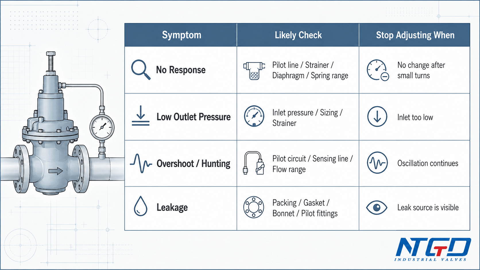
| Symptom | Mögliche Ursache | Adjustment / Inspection Direction | When to Stop Adjusting |
|---|---|---|---|
| Adjustment screw has no effect | Blocked pilot line, damaged diaphragm, low inlet pressure, broken spring, wrong spring range, blocked strainer | Verify inlet and outlet gauges; inspect pilot line, spring, diaphragm, strainer, and internals. | Stop when outlet pressure does not change after controlled adjustment. |
| Outlet pressure remains too low | Pilot set too low, insufficient inlet pressure, undersized valve, blocked strainer, high downstream demand | Confirm required set pressure and supply pressure before increasing setting. | Stop if inlet pressure is insufficient or demand exceeds valve capacity. |
| Outlet pressure remains too high | Over-adjusted screw, pilot fault, dirt on seat, bypass leakage, damaged diaphragm | Reduce setting gradually and verify outlet pressure. | Stop if pressure remains high after adjustment or bypass leakage is suspected. |
| Pressure overshoots | Oversized valve, unstable flow, dirt between seat and disc, poor pilot control | Avoid aggressive adjustment; allow stabilization and review valve sizing. | Stop if overshoot repeats under normal load. |
| Pressure fluctuates or hunts | Pilot instability, trapped air, blocked sensing line, changing demand, oversized valve | Prioritize inspection of the pilot circuit, sensing line, trapped air, flow range, and possible valve oversizing instead of trying to suppress pressure hunting by repeated screw adjustment. | Stop chasing pressure with repeated screw turns. |
| Das Ventil öffnet nicht | Plugged orifice, blocked strainer, defective diaphragm, insufficient pilot signal | Inspect strainer, orifice, diaphragm, and pilot line. | Stop if the valve does not respond after basic checks. |
| Das Ventil schließt nicht | Bypass leakage, pilot fault, dirt on seat, damaged diaphragm | Check bypass valve, pilot diaphragm, seat, and main valve. | Stop tightening the adjustment screw as a closing method. |
| Leakage near adjustment area | Damaged packing, gasket, bonnet seal, pilot fitting, or locknut area | Inspect sealing parts and follow service procedure. | Stop adjustment and isolate according to site procedure. |
Adjustment Screw Has No Effect
Never force the adjustment screw beyond its normal travel range. Forcing the screw can damage threads, overload the spring, damage the diaphragm mechanism, or leave the valve unable to hold a stable setting.
If the adjustment screw has no effect on outlet pressure, do not keep turning it. This is one of the most important troubleshooting signals.
Häufige Ursachen sind:
- blocked strainer;
- blocked pilot sensing line;
- low upstream pressure;
- damaged diaphragm;
- broken or wrong spring;
- dirt in the pilot valve seat;
- wrong valve size for the actual flow;
- bypass valve leakage.
In this situation, the adjustment screw is not the root cause. The valve and system condition should be inspected before further adjustment.
Outlet Pressure Remains Too Low
Low delivery pressure may occur when the valve setting is too low, but it can also occur when the upstream supply pressure is insufficient, the valve is undersized, the strainer is blocked, or the diaphragm is damaged.
Before increasing the setting, confirm the inlet pressure. A pressure reducing valve cannot maintain a downstream pressure higher than what the supply and valve design can support.
Outlet Pressure Is Too High or Overshoots
High outlet pressure after adjustment may be caused by over-adjustment, dirt on the seat, bypass leakage, pilot fault, or damaged internal parts. Overshoot under light load may also indicate an oversized valve or unstable operating condition.
Do not solve repeated overshoot by making large screw movements. Reduce the setting gradually, allow stabilization, and review the root cause.
Pressure Fluctuates or Hunts
Hunting or pressure fluctuation may occur when the valve is oversized, the pilot circuit is unstable, the sensing line is blocked, demand changes quickly, or trapped air affects pilot response.
For pilot-operated designs, check the pilot strainer, sensing line, pilot diaphragm, pilot seat, and stabilization time. Repeated adjustment without solving these issues can make control less stable.
Pilot-Operated PRV Problems to Check
For pilot-operated adjusting pressure reducing valves, review:
- pilot valve setting;
- pilot strainer blockage;
- trapped air in pilot tubing;
- blocked sensing line;
- pilot diaphragm condition;
- main valve diaphragm condition;
- pilot seat contamination;
- stabilization time after adjustment.
Pilot valve adjustment should be treated as part of the pressure control system, not as a simple screw movement.
Leakage Around the Adjustment Area
Leakage around the adjustment screw, bonnet, locknut, pilot fitting, or diaphragm cover is not a normal adjustment issue. It may indicate damaged packing, gasket failure, loose fittings, diaphragm damage, or body joint leakage.
Do not attempt to solve leakage by forcing the adjustment screw. Stop adjustment, isolate the valve according to site procedure, and inspect the sealing parts.
FAQ About Adjusting Pressure Reducing Valves
What does the adjustment screw do on a pressure reducing valve?
The adjustment screw changes spring compression or pilot setpoint, depending on the valve design. This changes the force balance that determines the downstream pressure setting. The final setting must still be verified with a downstream pressure gauge.
How do you adjust a pressure reducing valve?
To adjust a pressure reducing valve, confirm the required downstream pressure, check inlet and outlet pressure readings, loosen the locknut or jam nut, turn the adjustment screw gradually, allow the system to stabilize, verify downstream pressure, and secure the setting. The exact method should follow the valve design and manufacturer instructions.
Can I adjust a pressure reducing valve without a pressure gauge?
No. A downstream pressure gauge is needed to confirm the actual outlet pressure. Screw turns, sound, or flow feel cannot verify whether the valve is set safely. Industrial adjustment should be based on pressure readings, normal operating conditions where possible, and manufacturer instructions.
Which way do you turn a pressure reducing valve adjustment screw?
In many designs, clockwise adjustment increases spring compression and raises the downstream pressure setting, while counterclockwise adjustment lowers it. This is not universal. Always confirm the direction from the valve datasheet or IOM before adjustment.
What should a pressure reducing valve be set at?
A pressure reducing valve should be set according to the required downstream pressure for the system. In industrial service, this value depends on process requirement, downstream equipment limits, media, pressure class, valve design, and project specification. There is no universal industrial setting.
Why does the outlet pressure not change after adjustment?
If outlet pressure does not change after adjustment, the cause may be low inlet pressure, blocked strainer, blocked pilot line, damaged diaphragm, wrong spring range, pilot fault, bypass leakage, or incorrect valve sizing.
If the pressure reading does not change after a controlled adjustment, the operator should stop adjusting and treat the condition as a valve or system fault diagnosis, not as a request for more screw turns.
Is PRV adjustment the same as pressure reducing valve adjustment?
In many industrial and plumbing discussions, PRV is used as an abbreviation for pressure reducing valve. In this article, PRV adjustment means pressure reducing valve adjustment. However, PRV can also mean pressure relief valve in some contexts, so the valve type should always be confirmed.
When communicating with a supplier, maintenance team, or project engineer, specify whether PRV means pressure reducing valve or pressure relief valve to avoid selecting or adjusting the wrong valve type.
Is a pressure regulator the same as a pressure reducing valve?
In some water pressure discussions, pressure regulator and pressure reducing valve are used in similar ways. In industrial valve selection, terminology should be checked carefully because regulator, pressure reducing valve, and control valve can refer to different product designs depending on service, standard, and manufacturer.
Is pressure reducing valve adjustment the same as pressure relief valve adjustment?
No. A pressure reducing valve controls downstream pressure during normal operation by reducing higher inlet pressure, while a Druckbegrenzungsventil opens to release excess pressure during overpressure conditions. Their adjustment logic, safety function, and service requirements are different.
Does the adjustment procedure change for steam, water, gas, or hydraulic PRVs?
Yes. The general logic—confirm pressure, adjust gradually, check outlet pressure, and follow the valve manual—may be similar, but steam, water, gas, and hydraulic PRVs can have different media behavior, safety requirements, installation details, response speed, and service procedures. Service-specific instructions should be checked before adjustment.
Fazit
An adjusting pressure reducing valve is a product used to reduce and control downstream pressure, but its adjustment function is also a key part of its engineering value. The adjustment screw, spring, diaphragm, seat, pilot valve, and downstream pressure feedback all work together to determine how the valve responds.
Reliable pressure reducing valve adjustment depends on system requirement, gauge confirmation, small controlled changes, stabilization, and inspection when the valve does not respond. If pressure remains unstable, too high, too low, or unaffected by adjustment, the issue may be valve sizing, blockage, diaphragm damage, pilot fault, seat wear, or system condition rather than the screw setting alone.
For a reliable product review, the valve design, spring range, pressure requirement, flow range, media, and troubleshooting symptoms should be checked together rather than treated as separate issues.
Selecting or Reviewing an Adjusting Pressure Reducing Valve
When selecting or reviewing an adjusting pressure reducing valve, the most important information is not only the desired outlet pressure. The valve must also match the media, inlet pressure, flow range, temperature, pressure class, material, connection type, control stability requirement, and maintenance access.
For industrial pressure reducing valve selection, pressure setting review, or troubleshooting support, prepare the following information before technical review:
| Artikel zum Bestätigen | Warum es wichtig ist |
|---|---|
| Medien | Affects material, sealing, diaphragm, and service suitability. |
| Inlet pressure | Determines available supply pressure and pressure reduction range. |
| Required downstream pressure | Defines the target setting. |
| Flow range | Affects valve size, stability, and direct vs pilot design choice. |
| Temperatur | Affects material, diaphragm, gasket, and sealing selection. |
| Ventilgröße und Druckklasse | Must match pipeline and design conditions. |
| Verbindungstyp | Affects installation compatibility. |
| Direct-acting or pilot-operated design | Affects adjustment behavior and control stability. |
| Current pressure symptom | Helps determine whether the issue is adjustment, sizing, blockage, or component failure. |
NTGD Valve can help review the application when a pressure reducing valve must be selected, replaced, or checked for adjustment-related problems. The review should focus on product suitability first, then pressure setting and troubleshooting.
For abnormal pressure response, repeated setting drift, unstable outlet pressure, or suspected sizing mismatch before replacement or reselection, contact NTGD Valve for a technical review.
