Ball valve flow direction is a common question during valve selection, installation and site inspection. For many standard two-way ball valves, flow can usually pass through the valve in either direction because the valve has a straight-through bore and a symmetrical sealing arrangement.
However, this does not mean every ball valve can be installed without checking direction.
Some ball valve designs are directional. A flow arrow, vent hole, drain arrangement, V-port ball, single-seat design, cavity relief feature or special seat configuration may require the valve to be installed in a specific direction. In industrial pipelines, the correct answer should be confirmed by the valve body marking, datasheet, IOM manual, sectional drawing or manufacturer instruction.
This article explains when a ball valve is bidirectional, when direction matters, how to interpret a ball valve flow direction arrow, and what information should be checked before installation or RFQ.
Do Ball Valves Have a Flow Direction?
Quick Answer for Standard Ball Valves
Most standard two-way ball valves are usually bidirectional. Directional designs such as V-port, vented, drain, relief-hole, single-seat or special-seat ball valves must follow the body arrow, datasheet, IOM manual or manufacturer instruction.
In simple terms:
Most standard two-way ball valves do not have a fixed flow direction, but not all ball valves are non-directional. Always confirm the valve design before installation.
In a typical full-bore or reduced-bore two-way ball valve, the ball has a through-hole. When the bore is aligned with the pipeline, fluid passes through the valve in a relatively straight path. Because the valve seats are commonly arranged on both sides of the ball, many standard designs can handle flow from either direction.
This is why standard ball valves are commonly called bidirectional ball valves.
But the key word is standard. Direction must be checked whenever the valve includes a special port, special seat, body arrow, relief feature or manufacturer-defined installation direction.
The Important Exception: Not Every Ball Valve Is Non-Directional
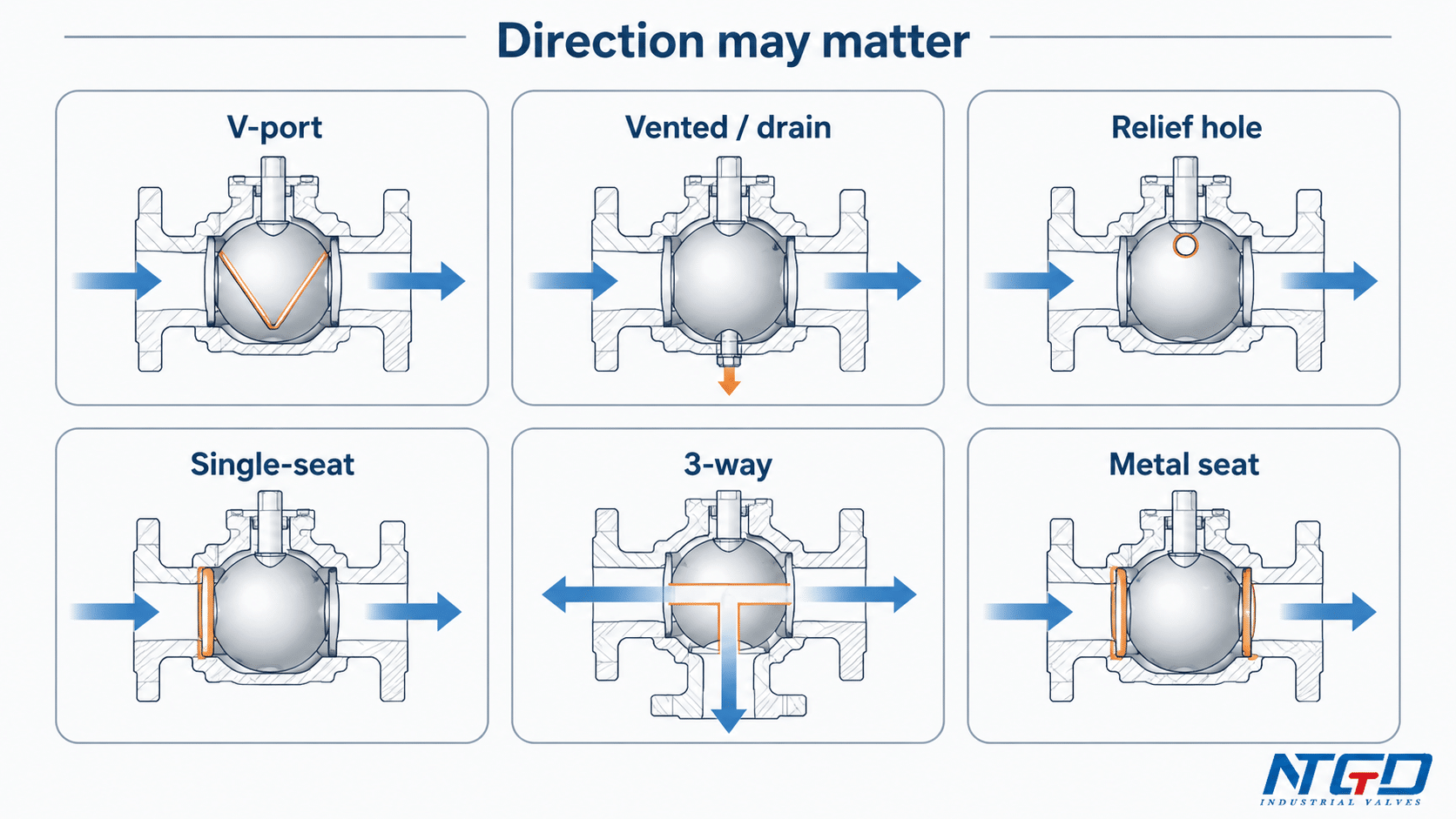
A ball valve may become directional when its design includes:
- a V-port or control-type ball;
- a single-seat or one-sided sealing arrangement;
- a vented ball, drain hole or relief hole;
- a cavity pressure relief feature;
- a special metal seat or severe-service seat design;
- a 3-way or multi-port flow pattern;
- a manufacturer-specified pressure-bearing direction;
- a body arrow or tag indicating preferred installation direction.
So the practical answer is:
Most standard two-way ball valves are usually bidirectional, but some ball valve designs are directional. Always check the valve body arrow, datasheet, IOM manual and seat design before installation.
Ignoring this distinction can lead to sealing problems, incorrect control behavior, ineffective pressure relief, or installation rework in high-pressure, special-media or direction-sensitive services.
What Ball Valve Flow Direction Means
Ball valve flow direction refers to the intended direction of media flow through the valve body and ball bore. In a simple two-way valve, this means whether the fluid enters from the left or right side of the valve.
However, several terms are often confused:
| Term | What It Means | Why It Matters |
|---|---|---|
| Flow direction | Direction of media movement through the valve | Determines whether the valve is installed with or against the intended flow path |
| Handle position | Visual indication of open or closed position | Shows valve status, but does not define the required flow direction |
| Pressure direction | Direction from which differential pressure acts on the valve | Important for sealing load, seat behavior and pressure relief design |
| Sealing direction | Direction in which the valve is designed or tested to seal | Important when leakage class or shutoff direction matters |
| Preferred orientation | Manufacturer-recommended installation direction | May depend on vent, drain, relief hole, seat or service condition |
A common mistake is to use the handle position as the only indication of ball valve flow direction. This is not reliable.
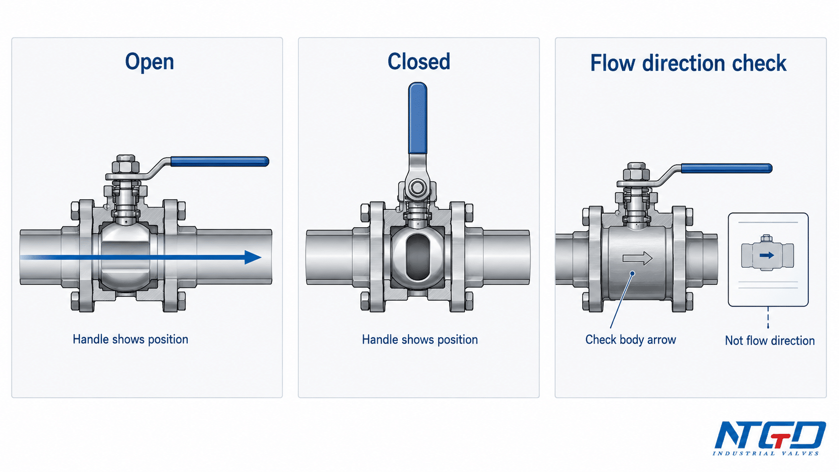
Flow Direction vs. Open / Closed Handle Position
For many manual ball valves, the handle position gives a quick visual clue:
- handle parallel to the pipe usually means the valve is open;
- handle perpendicular to the pipe usually means the valve is closed.
This allows field operators to quickly verify valve status from a distance, but it still does not identify the required flow direction.
In a standard bidirectional valve, the handle may show the operating position while the valve still allows flow from either side. In a directional valve, the handle may show open or closed status, but the correct installation direction still depends on the body arrow, seat design, vent arrangement or manufacturer documentation.
Flow Direction vs. Pressure Direction and Sealing Direction
Flow direction and pressure direction can also be different from sealing direction.
For example, a valve may allow flow in both directions but achieve better sealing performance from one pressure side. In another case, a valve may be tested for bidirectional shutoff, while a special relief feature still requires attention to installation direction.
This is why bidirectional flow should not be treated as the same thing as bidirectional sealing or bidirectional isolation.
For industrial projects, the question is not only:
Can media pass through the valve from either side?
The more important questions are:
- Can the valve seal properly from both pressure directions?
- Does the seat design support reverse pressure?
- Is there a relief hole or cavity relief path?
- Does the datasheet specify a preferred direction?
- Is there a body arrow or flow tag?
- Does the application include flow reversal?
In applications with high differential pressure, reverse pressure, hazardous media or strict leakage requirements, bidirectional flow is not enough. The buyer should confirm whether the valve also provides bidirectional shutoff or bidirectional pressure sealing.
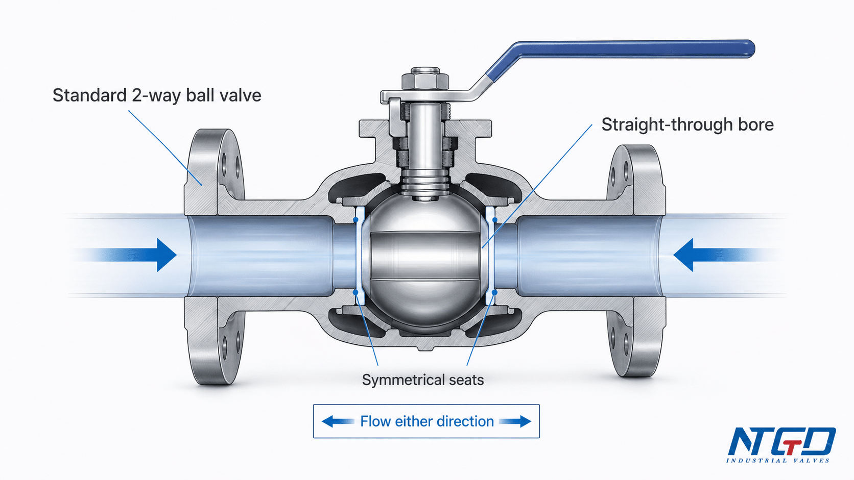
Why Standard 2-Way Ball Valves Are Usually Bidirectional
Symmetrical Bore and Straight-Through Flow Path
A standard two-way ball valve has a ball with a hole through the center. When the valve is open, this hole aligns with the pipeline and creates a straight-through flow path. Because the flow path is generally symmetrical, the valve can often handle flow from either direction.
This is different from valves that have a clearly shaped internal flow path, such as many globe valves or check valves. A standard ball valve does not normally rely on a disc lifting from one side of a seat or a flap opening under flow pressure. Instead, the ball rotates 90 degrees to open or close the bore.
This geometry is one reason why standard ball valves are widely used for on-off service in industrial pipelines.
Many standard 2-piece and 3-piece two-way ball valves use a similar straight-through bore and are typically bidirectional, but the seat design and manufacturer documentation still control the final decision.
Seat Arrangement and Bidirectional Flow Capability
Many standard ball valves have seats on both sides of the ball. These seats support the ball and provide sealing when the valve is closed. In common soft-seated designs, the seat arrangement often allows the valve to shut off flow from either side under normal service conditions.
This bidirectional behavior is common in many standard floating ball valves, while some trunnion-mounted designs may require separate confirmation of pressure direction, seat configuration and cavity relief logic.
For a fuller comparison of ball support, sealing load path and seat behavior, see the trunnion vs floating ball valve guide.
The actual behavior still depends on:
- floating or trunnion-mounted design;
- upstream and downstream seat arrangement;
- soft seat or metal seat;
- pressure class;
- temperature;
- media;
- pressure direction;
- manufacturer test standard;
- whether the application requires tight shutoff in both directions.
Why “Bidirectional Flow” Still Needs Design Confirmation
Even when a ball valve can pass flow in either direction, the buyer should still confirm whether the valve is suitable for the specific service.
A valve may be acceptable for bidirectional flow, but not necessarily for every combination of:
- high differential pressure;
- reverse pressure;
- abrasive media;
- high temperature;
- cryogenic service;
- cavity pressure relief;
- tight shutoff requirements;
- emergency isolation;
- frequent flow reversal.
For this reason, the safest wording is:
A standard two-way ball valve is usually bidirectional, but the final installation direction should be confirmed by the valve design and manufacturer documentation.
For pipeline valve projects, confirm the datasheet and IOM together with the applicable valve standard, such as API Specification 6D, before finalizing design, testing and documentation requirements.
If the application includes high differential pressure, reverse pressure, hazardous media, tight shutoff, cavity relief or regular flow reversal, do not assume bidirectional capability. Confirm it before ordering or installation.
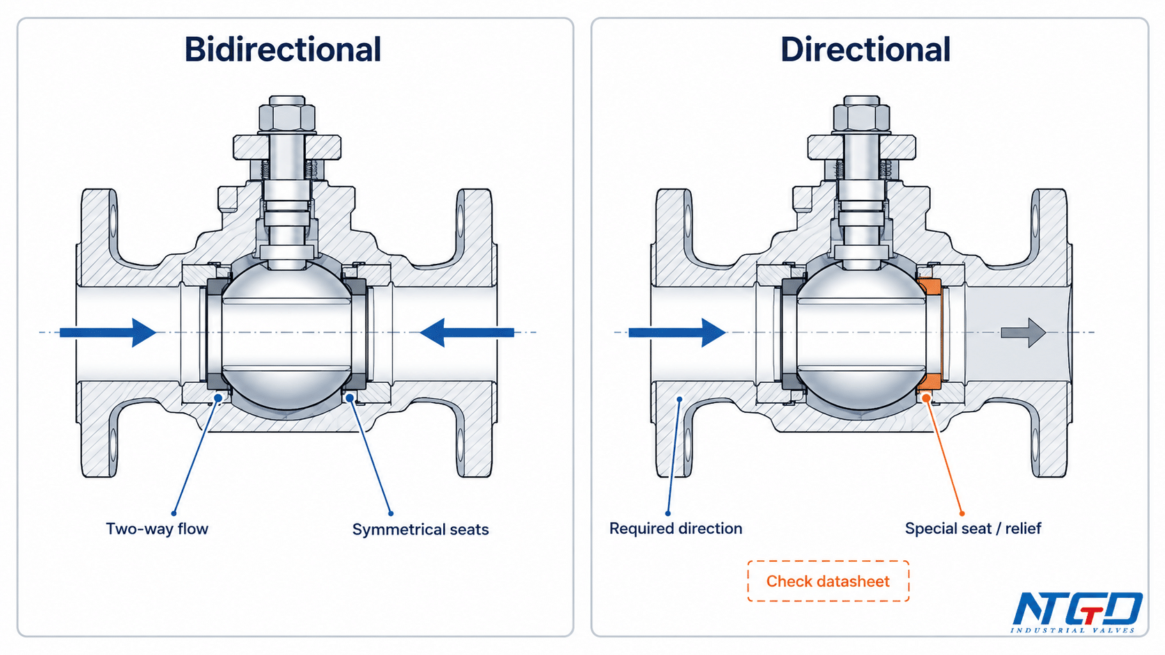
Bidirectional vs Directional Ball Valves
A bidirectional ball valve and a directional ball valve may look similar externally, especially when both are installed between pipe flanges or threaded ends. The difference is inside the valve design.
The following table summarizes the practical distinction.
| Valve Design | Flow Direction Behavior | Seat / Sealing Logic | Installation Requirement | If Installed Reversed | What Buyer Should Check |
|---|---|---|---|---|---|
| Standard bidirectional two-way ball valve | Usually allows flow from either side | Seats are commonly arranged to support sealing from both sides in normal service | Usually no fixed flow direction, unless marked otherwise | Often no issue in normal service, but confirm pressure and sealing requirements | Datasheet, seat design, test direction, pressure rating |
| Directional ball valve | Designed for preferred or required flow direction | Seat, port, vent, drain or relief feature may work correctly only in one direction | Must follow body arrow or manufacturer instruction | May reduce sealing reliability, affect control behavior or create pressure relief risk | Body arrow, IOM manual, sectional drawing, relief path |
| Unidirectional ball valve | Intended for one-way flow or one pressure direction | One-sided sealing or pressure-assisted design | Must be installed in the specified direction | May leak, fail to seal, trap pressure or operate incorrectly | Seat design, pressure direction, shutoff requirement |
| Metal-seated / severe-service ball valve | Depends on service condition and seat design | Seat load, wear pattern and reverse pressure behavior may affect sealing | Confirm case by case | Risk depends on pressure direction, seat load design and application | Seat design, differential pressure, reverse pressure expectation |
| Trunnion-mounted ball valve with special seat or cavity relief design | Depends on seat configuration and cavity relief design | Flow may be bidirectional while sealing, pressure relief or isolation behavior is design-dependent | Confirm case by case | Not all trunnion valves are directional, but special seat or relief designs may require direction check | Seat configuration, DBB / DIB requirement, cavity relief design |
Bidirectional Flow Does Not Always Mean Bidirectional Sealing
This is one of the most important engineering distinctions.
A valve may allow media to flow through the bore from either side when open. That is bidirectional flow.
But when the valve is closed, the sealing behavior depends on how pressure acts on the ball and seats. Some designs may seal from both directions. Others may have a preferred pressure side or a relief path that changes how trapped cavity pressure is handled.
| Term | Practical Meaning |
|---|---|
| Bidirectional flow | Media can pass through either direction when the valve is open |
| Bidirectional shutoff | The closed valve is designed to seal from both pressure directions |
| Bidirectional isolation | Isolation function such as DBB / DIB must be confirmed by design and testing, not assumed from flow direction |
For isolation terminology, OSHA’s double block and bleed definition describes two closed in-line valves with a drain or vent valve opened between them, so DBB / DIB isolation should not be assumed from bidirectional flow alone.
For basic water, air or clean fluid service, this distinction may not become a serious issue. For industrial service involving high pressure, hazardous media, high temperature, abrasive particles or strict leakage requirements, it becomes more important.
Before specifying a ball valve as bidirectional, the buyer should clarify whether the project requires:
- bidirectional flow only;
- bidirectional shutoff;
- bidirectional pressure sealing;
- double block and bleed function;
- reverse pressure capability;
- cavity pressure relief in a defined direction.
These are not the same requirement.
When Ball Valve Flow Direction Becomes Critical: Directional Design Exceptions
The following designs may require a specific ball valve flow direction and should not be treated as standard bidirectional valves without confirmation.
The goal is not to turn this article into a ball valve types guide, but to identify the main cases where direction should be checked carefully.
| Design / Feature | Why Direction May Matter | Risk if Reversed | What to Verify |
|---|---|---|---|
| V-port ball valve | The V-shaped opening is designed for controlled flow characteristics | Flow control behavior may change; throttling performance may not match design intent | Flow arrow, control direction, datasheet |
| Segment / eccentric ball valve | The ball or segment may interact with the seat in a defined direction | Uneven wear, poor control or sealing instability | Seat contact direction, actuator position, manufacturer manual |
| Single-seat ball valve | Sealing may be optimized from one pressure side | Leakage or reduced shutoff performance | Seat arrangement and shutoff direction |
| Vented ball valve | Vent hole position may be direction-sensitive | Incorrect venting or trapped pressure risk | Vent hole location and installation instruction |
| Drain ball valve | Drain orientation may depend on system layout and valve design | Drain function may not work as expected | Drain side and piping orientation |
| Relief-hole / cavity relief design | Pressure relief path may be directed to a specific side | Cavity pressure may not relieve as intended | Relief hole direction, relief path, manufacturer drawing |
| 3-way / multi-port ball valve | Flow path depends on port arrangement, L-port or T-port design | Wrong flow routing or unintended mixing / diversion | Port drawing and handle position diagram |
| Metal-seated / severe-service ball valve | Seat load, erosion and pressure direction may affect sealing | Risk depends on pressure direction, seat load design and application | Seat design, flow direction, differential pressure |
| Trunnion-mounted ball valve with special seat design | Seat behavior may depend on pressure direction and cavity relief logic | Depends on seat configuration and cavity relief design; not all trunnion valves are directional | Seat configuration, DBB / DIB requirement, cavity relief design |
V-Port, Segment and Control-Type Ball Valves
V-port ball valves are often used when the valve is expected to provide more controlled flow regulation than a standard on-off ball valve. The V-shaped opening changes how the flow area opens as the ball rotates.
Because the port geometry affects control behavior, direction may matter more than in a basic two-way on-off valve. The correct direction should be confirmed from the valve drawing or manufacturer instruction rather than assumed from the general rule for standard ball valves.
For a deeper explanation of how the characterized opening affects throttling and flow modulation, see NTGD’s guide to V-port ball valve flow control.
Vented, Drain and Relief-Hole Ball Valves
Vented or drain ball valves require special attention because the vent or drain feature is part of the pressure management function. If the valve is installed in the wrong direction, the vent or relief feature may not behave as intended.
A relief hole in the ball, for example, may be designed to relieve trapped cavity pressure to a specific side of the pipeline. This does not mean every ball valve with a hole is unsafe in reverse direction, but it does mean the installation direction must be verified.
For volatile, cryogenic, gas or pressure-relief-sensitive service, the vent, drain or relief path must be verified against the manufacturer’s drawing or IOM before installation.
Single-Seat, Cavity Relief and Severe-Service Designs
Some ball valves are designed with one primary sealing direction or a special cavity relief logic. In severe service, the relationship between pressure, seat load, flow direction and leakage risk becomes more important.
When seat material is part of the direction or shutoff review, compare metal-seated and soft-seated ball valves before confirming reverse pressure or severe-service requirements.
Examples include applications with:
- high pressure differential;
- high temperature;
- abrasive media;
- metal seats;
- gas service;
- hazardous media;
- reverse pressure;
- strict leakage class requirements.
In these cases, a simple statement such as “ball valves are bidirectional” is not enough. The seat design and test conditions must be checked.
3-Way and Multi-Port Ball Valves
A 3-way ball valve should not be treated the same as a standard two-way ball valve. In a 3-way design, the internal port arrangement controls how flow is diverted, mixed or isolated.
The question is not only “which side is inlet and outlet?” but also:
- Is it an L-port or T-port?
- Which port is common?
- Which handle position connects which ports?
- Does the valve divert, mix or isolate?
- Does the project drawing define the flow path?
For this reason, 3-way ball valve flow pattern should normally be handled by the valve drawing or a detailed 3-way selection guide, not by a generic flow direction rule.
For detailed L-port, T-port, diverting, mixing and port-pattern logic, refer to NTGD’s 3-way ball valve L-port and T-port guide.
What Does the Flow Arrow on a Ball Valve Mean?
A flow arrow on a ball valve body should be taken seriously, but it should not be interpreted too simplistically.
In many cases, a body arrow indicates the manufacturer’s intended flow direction. In other cases, the marking may relate to pressure-bearing direction, preferred orientation, vent / drain function or project flow direction.
The meaning should be confirmed by the valve datasheet, IOM manual or drawing.
| Arrow / Marking May Indicate | Meaning | What to Check |
|---|---|---|
| Flow direction | Manufacturer-intended media flow path | Cross-check body marking with datasheet and IOM |
| Pressure-bearing direction | Preferred high-pressure side or sealing direction | Confirm high-pressure side, seat design and sectional drawing |
| Preferred orientation | Recommended installation direction for reliable service | Check manufacturer instruction and project specification |
| Vent / drain / relief side | Direction-sensitive venting, drainage or cavity relief function | Verify relief path, drain orientation and manufacturer instruction |
| P&ID / drawing arrow | Project flow direction on the system drawing; not the same as the manufacturer body arrow on the valve | Check drawing legend, valve tag and line flow direction |
| Nameplate / tag marking | Model-specific installation or function note | Use model code to locate the correct technical datasheet |
Flow Arrow, Body Marking and Manufacturer-Preferred Direction
If a ball valve body has a clear flow arrow, the safest practice is to install the valve according to that arrow unless the manufacturer documentation states otherwise.
The body arrow may be especially important when the valve includes:
- a V-port;
- a vented ball;
- a drain feature;
- a relief hole;
- a one-way seat arrangement;
- a pressure-assisted sealing design;
- a project-specific flow direction requirement.
Ignoring a body arrow can create unnecessary risk, even if the valve appears to be a simple two-way ball valve.
Arrow Direction vs. Pressure-Bearing Direction
The arrow may not always represent only the direction in which media flows during normal operation. In some designs, it may also indicate the direction from which pressure is expected to act on the seat.
This matters because sealing performance can depend on how pressure loads the seat and ball. If the valve is installed in the opposite direction, the valve may still pass flow, but its sealing or pressure relief behavior may not match the intended design.
In high-pressure or tight-shutoff service, installing against the intended pressure-bearing direction may reduce sealing reliability or change how the seat is loaded, even if the open valve can still pass flow.
What If There Is No Arrow on the Valve Body?
If there is no arrow on the valve body, the valve may be a standard bidirectional design, but this should not be treated as an absolute rule.
No arrow can mean:
- the valve is generally non-directional in standard service;
- the direction is not critical for that design;
- the direction is defined elsewhere in the datasheet or IOM;
- the marking is absent due to product size, body design or manufacturing style.
For non-critical clean service, a standard two-way ball valve without an arrow is often installed according to piping layout and accessibility. For industrial service, especially high-pressure or special-seat applications, the datasheet and manufacturer instruction should still be checked.
How to Check Ball Valve Installation Direction Before Installation
This section is a direction-check process, not a full ball valve installation guide. It does not cover pipe preparation, thread sealing, flange bolting, pressure testing or commissioning. Those belong to a dedicated installation procedure.
For the full sizing, connection, testing and installation workflow, use the dedicated Ball Valve Sizing and Installation Guide instead of treating flow-direction checking as a complete installation procedure.
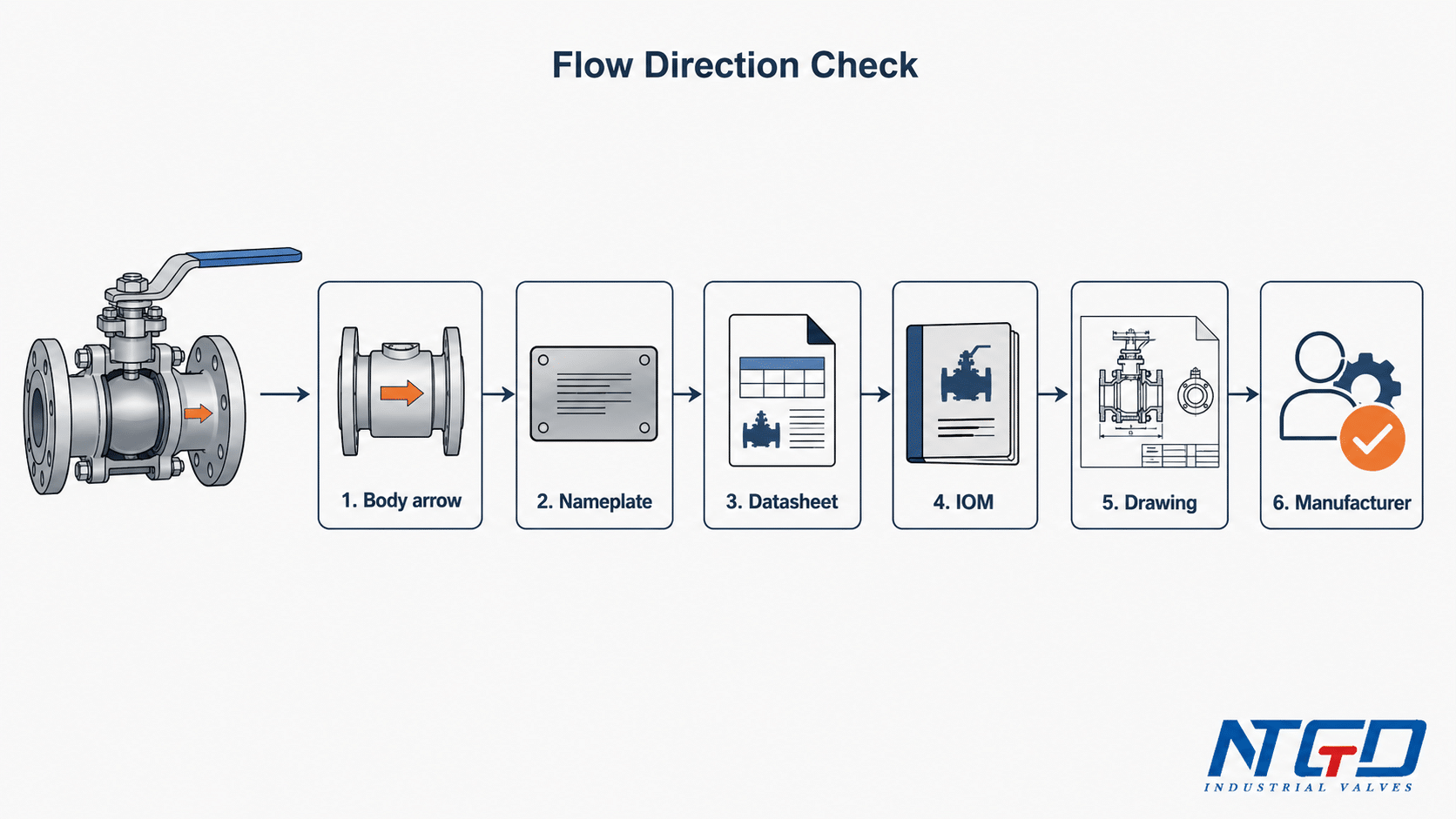
The following sequence starts with the most direct indicators and moves toward documentation and manufacturer confirmation when the design is unclear.
| Check Step | What to Look For | Why It Matters | If Unclear |
|---|---|---|---|
| 1. Valve body arrow | Cast or stamped arrow on body | Indicates intended flow or preferred direction | Follow manufacturer documentation |
| 2. Nameplate / tag | Model number, flow tag, service tag — use this to locate the correct datasheet and IOM | Links the valve to manufacturer documentation for flow direction, seat design and pressure direction | Check datasheet and IOM |
| 3. Datasheet | Flow direction, seat type, pressure rating | Confirms design limitations | Ask supplier or manufacturer |
| 4. IOM manual | Installation direction and orientation notes | Defines correct installation practice | Use project-approved document |
| 5. P&ID / piping drawing | Project flow direction and valve tag | Aligns valve with system design | Confirm drawing legend |
| 6. Sectional drawing | Internal port, seat and relief-hole geometry | Shows whether direction affects function | Request sectional drawing |
| 7. Seat / relief design | Single-seat, vented, relief-hole or cavity relief feature | Determines sealing and pressure relief behavior | Confirm with manufacturer |
| 8. Manufacturer confirmation | Written clarification for critical service | Reduces installation and service risk | Request written manufacturer clarification or an updated datasheet for critical service |
Vertical, Horizontal and Stem Orientation Notes
Many ball valves can be installed in horizontal or vertical pipelines, but this depends on size, weight, actuator arrangement, drain / vent function and manufacturer instruction.
For small manual valves in clean service, orientation may be less critical. For larger industrial valves, actuated valves or valves with drain / vent features, orientation should be checked carefully.
Important considerations include:
- whether the actuator or gearbox needs support;
- whether the stem position affects maintenance access;
- whether the vent or drain point remains functional;
- whether the handle position is visible and safe for operators;
- whether pipeline stress may load the valve body;
- whether project specifications define a required orientation.
Again, this is not the same as a full installation method. It is a direction and orientation check before installation.
When to Confirm with the Manufacturer
Manufacturer confirmation is recommended when:
- the valve has a flow arrow but the piping direction is different;
- the valve has no arrow but the service is high risk;
- the valve is V-port, 3-way, vented, drain or relief-hole type;
- the valve is metal seated or severe-service;
- the project requires reverse pressure sealing;
- the valve is used in hazardous, high-temperature or high-pressure service;
- the valve will experience regular flow reversal;
- the P&ID and valve marking appear inconsistent.
For critical service, a short written clarification is more reliable than assuming that all ball valves behave the same way.
Common Mistakes and RFQ Checks for Ball Valve Flow Direction
Common Mistakes to Avoid
| Mistake | Why It Matters | Correct Check |
|---|---|---|
| Assuming all ball valves are bidirectional | Some designs are directional or have pressure-sensitive features | Check seat design, datasheet and body marking |
| Ignoring a body arrow | Arrow may indicate flow direction, pressure direction or special feature | Confirm arrow meaning in IOM / datasheet |
| Treating handle direction as flow direction | Handle usually shows open / closed status, not design flow direction | Use body marking and documentation |
| Installing a directional valve backwards | May affect sealing, control behavior or pressure relief | Follow manufacturer instruction |
| Ignoring vent / drain / relief holes | These features may be direction-sensitive | Check sectional drawing and relief path |
| Confusing flow with sealing | Flow may be bidirectional while sealing is design-dependent | Confirm shutoff direction and leakage requirement |
| Using installation direction as a full installation method | Direction check is not the same as installation procedure | Follow dedicated installation guide and project procedure |
| Treating no-arrow valves as always bidirectional | No arrow is not a universal rule | Verify datasheet for critical service |
Information to Provide Before RFQ or Specification Review
Use the following as a pre-RFQ checklist: if any item indicates a directional, vented, drain, relief, V-port, special-seat or reverse-flow condition, ask the supplier to confirm flow direction and sealing behavior.
| Information to Provide | Why It Matters for Flow Direction |
|---|---|
| Valve type | If V-port, 3-way, vented, drain, relief-hole or single-seat design is involved, ask for the required flow direction |
| Size and pressure class | Larger or higher-pressure valves may have more specific seat behavior |
| Media | Corrosive, abrasive or hazardous media increases sealing and material risk |
| Temperature | Affects seat material and pressure relief behavior |
| Differential pressure | Determines pressure loading on seats |
| Flow reversal possibility | If reverse flow may occur, confirm whether bidirectional shutoff is required beyond bidirectional flow |
| Seat design | If single-seat, metal-seat or special seat arrangement is used, verify sealing direction and reverse pressure capability |
| Required shutoff direction | Defines whether leakage control is needed from one or both sides |
| Vent / drain / relief feature | May require specific installation direction |
| Drawing or valve tag | Helps match valve orientation with project flow direction |
| Installation orientation | Horizontal, vertical, actuator position and access requirements |
| Actuation and operating frequency | May affect orientation, torque and maintenance access |
For NTGD or any industrial valve supplier to confirm the correct recommendation, the RFQ should not only state “ball valve.” It should describe the service conditions, pressure direction, flow reversal requirement and any directional features.
A standard bidirectional valve may be suitable for many applications. A directional design may be safer or required when the service condition, seat design or pressure relief logic demands it.
FAQ: Ball Valve Flow Direction
Do ball valves have a flow direction?
Most standard two-way ball valves are usually bidirectional, so flow can often pass through either side. However, some ball valve designs are directional and must follow the body arrow, datasheet or manufacturer instruction.
Are ball valves directional?
Some ball valves are directional, but many standard two-way ball valves are not direction-sensitive in normal service. Direction depends on the valve design, seat arrangement, flow arrow, vent / relief feature and application requirement.
Are ball valves bidirectional?
Many standard ball valves are bidirectional for flow. However, bidirectional flow does not always mean bidirectional sealing or bidirectional isolation. For critical service, confirm the seat design and pressure direction.
Can a ball valve be installed backwards, and what happens if it is?
A standard bidirectional ball valve may operate normally in either direction under suitable service conditions. A directional ball valve, vented ball valve, V-port valve, relief-hole design or single-seat valve may have poor sealing, incorrect control behavior, ineffective venting, trapped cavity pressure or increased wear if installed backwards.
What does the arrow on a ball valve mean?
The arrow may indicate flow direction, preferred pressure direction, manufacturer-recommended orientation, or the direction related to a vent, drain or relief feature. Always confirm the meaning with the datasheet or IOM manual.
Can a ball valve be installed opposite the arrow?
It should not be installed opposite the arrow unless the manufacturer confirms that reverse installation is acceptable for the specific valve design and service condition.
Can I reverse a ball valve if there is no arrow on the body?
A valve with no arrow may be a standard bidirectional design, but no arrow is not a universal rule. In industrial service, especially with high pressure, reverse pressure, special seats or relief features, confirm the datasheet or manufacturer instruction before reversing the valve.
Does handle direction show flow direction?
No. Handle position normally shows open or closed status only. For flow direction, check the valve body arrow, datasheet or manufacturer documentation.
Can a ball valve be installed vertically or horizontally?
Many ball valves can be installed in vertical or horizontal pipelines, but large valves, actuated valves, vented / drain designs and project-specific installations should follow the manufacturer instruction and project specification.
Why do vented or drain ball valves require a specific flow direction?
Vented, drain or relief-hole ball valves can be direction-sensitive because the vent, drain or relief path may depend on the hole location and pressure side. Confirm the correct orientation before installation.
Are all quarter-turn ball valves bidirectional?
No. Quarter-turn describes the valve operation, not the flow direction rule. A quarter-turn valve can be bidirectional or directional depending on its internal design and manufacturer specification.
Does it matter which direction you install a ball valve?
For many standard two-way ball valves, direction may not matter in normal service. For directional designs, special seats, body arrows, vented / drain features, relief holes, V-port balls or reverse-pressure service, direction should be confirmed before installation.
Conclusion
Ball valve flow direction should not be answered with a simple “always yes” or “always no.” Most standard two-way ball valves are usually bidirectional because their straight-through bore and seat arrangement allow flow from either side. But special designs can be directional.
Before installation, check the valve body arrow, nameplate, datasheet, IOM manual, P&ID, sectional drawing and seat / relief design. Pay special attention to V-port valves, vented or drain ball valves, relief-hole designs, single-seat valves, 3-way valves, metal-seated valves and high-pressure applications.
For industrial projects, the safest approach is to treat ball valve flow direction as a design confirmation issue. If the service involves flow reversal, strict shutoff, high pressure, hazardous media or special valve features, confirm the required direction before installation or RFQ.
Application / Specification Support
For direction-sensitive applications, provide the valve type, seat design, pressure direction, flow reversal requirement and any body marking or drawing before requesting technical clarification or submitting an RFQ.
For product-level specification support, NTGD’s industrial ball valve range can be reviewed together with the RFQ checklist above.
NTGD can review these details to help confirm whether a standard bidirectional ball valve or a direction-sensitive design is more suitable for the application.
