Correct ball valve sizing is not the same as matching the valve to the pipe’s nominal size. In industrial systems, a valve that looks correct on a line drawing can still become a flow restriction, a pressure-loss point, or a leakage risk if the bore, Cv/Kv value, port design, pressure rating, material route, and installation conditions are not checked together.
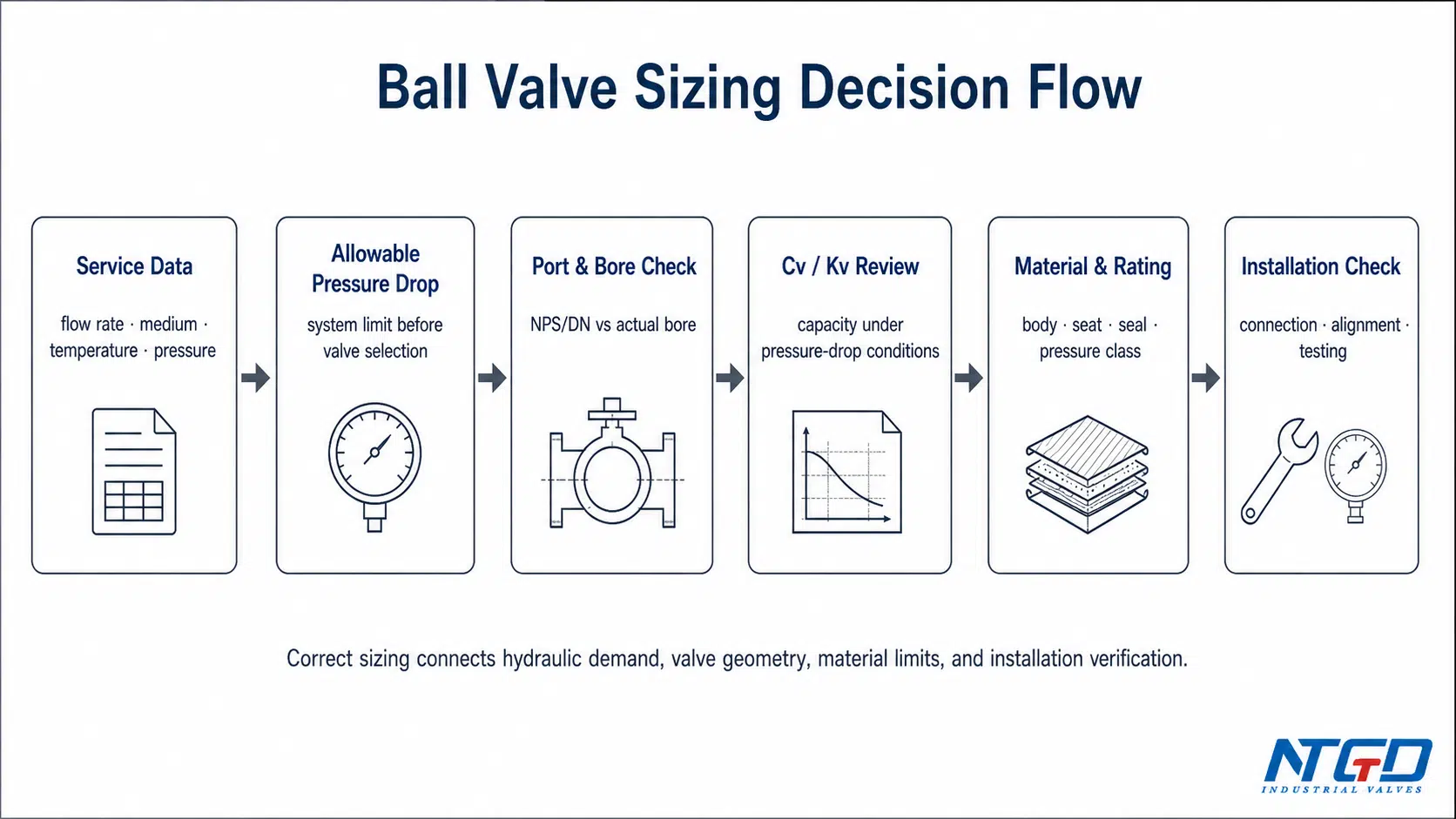
This article is written for industrial ball valve selection and installation readiness. It is not a DIY plumbing replacement guide. The practical sequence is:
- Start with service data, not pipe size alone: confirm flow rate, allowable pressure drop, medium, temperature, pressure, and connection type.
- Check the real flow path: compare NPS / DN with actual bore, port design, and manufacturer Cv/Kv data.
- Match the valve to the service condition: full port, reduced port, V-port, seat material, body material, and pressure class all change the final decision.
- Use installation as the final performance check: alignment, pipe support, connection sealing, leak testing, pressure testing, and cycle testing protect the sizing decision after the valve is installed.
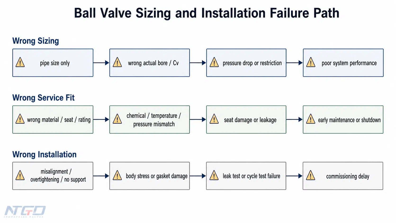
A well-sized ball valve can still fail if it is installed under pipe stress or without testing. A well-installed valve can still restrict the system if the port, bore, Cv/Kv, or material route is wrong. The strongest approach is to treat sizing and installation as one engineering sequence.
Why Proper Ball Valve Sizing Affects Flow, Pressure Drop, and Service Life
A ball valve is selected for fast quarter-turn operation, tight shutoff, and low flow resistance when fully open. Those advantages only hold when the valve’s internal geometry, port route, material limits, and installation conditions match the system’s hydraulic and service demands. If the sizing is wrong, the valve can turn from a low-resistance isolation device into a permanent restriction point.
Undersizing, Oversizing, and Wrong Port Selection
An undersized ball valve restricts the flow path. Even when the pipe size is correct, the valve may become a bottleneck if the actual bore or port area is too small. That restriction can raise velocity, increase pressure drop, create noise or vibration, and accelerate seat wear.
An oversized valve is not automatically safer. A larger body may add unnecessary purchase cost, installation weight, actuator load, support requirements, and maintenance space. In some systems, oversizing solves none of the real hydraulic problems because the issue is not body size, but bore route, Cv/Kv value, material compatibility, or installation stress.
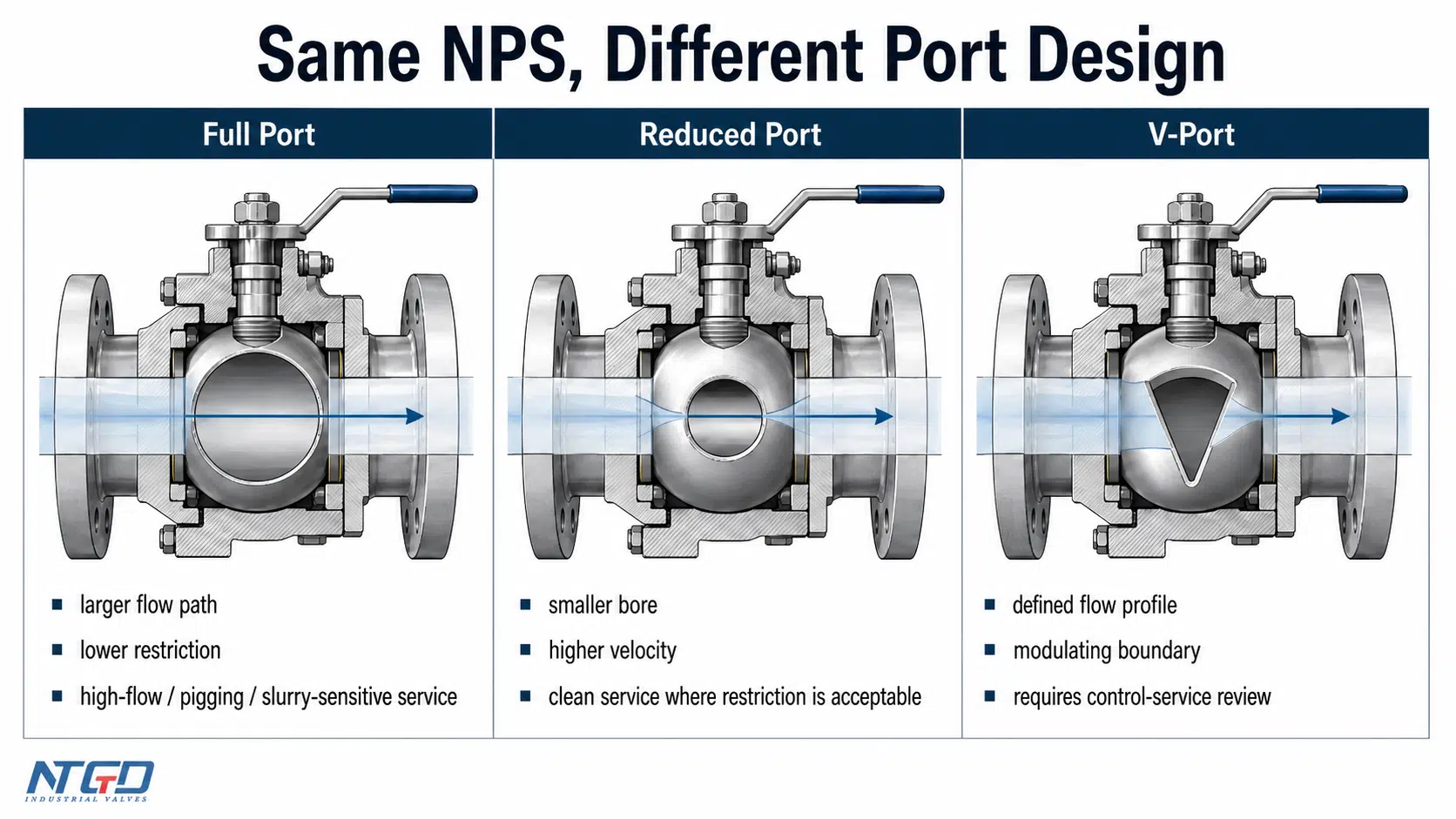
The more common sizing failure is selecting the wrong port route. A reduced port ball valve and a full port ball valve may share the same nominal size, but they do not provide the same flow capacity.
| Sizing Issue | What Happens in the System | Typical Result |
|---|---|---|
| Valve bore too small | Flow is forced through a restricted opening | Higher velocity, pressure-drop increase, noise or vibration, and faster seat wear |
| Valve oversized without need | Larger body, weight, and installation envelope | Higher purchase cost, larger support or actuator burden, and possible maintenance access problems |
| Wrong port design | Nominal size matches the pipe, but actual bore does not match flow demand | Unexpected flow restriction, lower effective capacity, or poor performance during peak demand |
| Wrong Cv/Kv value | Valve cannot pass the required flow under the allowable pressure drop | Flow demand is not met even though the valve size appears correct |
| Wrong pressure or material route | Valve fits dimensionally but does not match the real service | Leakage, corrosion, seat damage, or commissioning rejection |
Pressure Drop, Velocity, and Flow Disruption
Pressure drop across a ball valve depends on internal geometry, port size, bore profile, and flow coefficient. A correctly selected valve should pass the required flow while keeping pressure loss within the acceptable system limit.
For clean liquid service where pressure drop is not sensitive, a reduced port valve may be acceptable. For high-flow service, low-pressure-drop service, pigging lines, viscous fluids, or media with solids, a full port design is often the safer route because the valve should not become the smallest flow path in the line.
If the valve will be used for modulation or control, a V-port ball valve may be considered. That does not make it a standard on/off ball valve sizing case. V-port selection should be reviewed as a control-oriented application, especially when actuator sizing, control profile, and repeatable positioning are involved.
Maintenance and Lifecycle Cost Effects
Incorrect ball valve sizing often appears later as a maintenance problem. High velocity can accelerate seat wear. Excessive pressure drop can reduce pump efficiency or create downstream performance issues. Misalignment during installation can load the valve body and damage seals or connections. Skipping post-installation testing can leave small leaks or torque problems undiscovered until commissioning.
The purchase cost of a ball valve is only one part of the lifecycle decision. The larger cost often comes from removing, replacing, retesting, and restarting a valve that was sized or installed incorrectly.
Key Data Needed Before Sizing a Ball Valve
Before making a ball valve selection, define the operating conditions. The specification should come from system data, not from pipe size alone. Missing or inaccurate input data can lead to the wrong bore route, Cv/Kv value, pressure class, material route, connection type, or installation method.
Required Flow Rate and Allowable Pressure Drop
Start with the required flow rate. This may be given in GPM, m³/h, L/min, or another project-specific unit. The value should reflect real operating demand, not only maximum pipe capacity.
Then define the allowable pressure drop. This is the maximum pressure loss the system can tolerate across the valve while still maintaining stable operation. A valve with the correct nominal size may still be unsuitable if its bore or Cv/Kv creates too much pressure loss.
For ball valve sizing, the central question is:
Can this valve pass the required flow at the allowed pressure drop under the actual service conditions?
That cannot be answered from pipe diameter alone.
Operating Pressure, Temperature, and Medium
The valve must match system pressure and temperature. Working pressure, design pressure, pressure class, temperature range, and pressure-temperature limits all affect suitability.
The medium also changes the sizing decision. Clean water, oil, gas, solvent, corrosive liquid, slurry, viscous fluid, and solid-laden media do not behave the same through the valve. Viscosity, solids content, corrosion risk, and cleanliness influence bore selection, seat route, material selection, and installation inspection.
| Data to Confirm | Why It Matters for Ball Valve Sizing |
|---|---|
| Flow rate | Defines the required flow capacity and supports Cv/Kv and port route review |
| Allowable pressure drop | Determines whether the selected valve will restrict flow beyond the system’s tolerance |
| Operating pressure | Confirms pressure class, body rating, and end connection suitability |
| Temperature | Affects seat, seal, body material, and pressure-temperature limits |
| Medium | Determines corrosion, abrasion, sealing, cleaning, and material compatibility risks |
| Viscosity or solids | Strongly influences full port vs reduced port selection and cleaning access |
| Pipe size and connection | Controls dimensional fit, end connection route, and installation method |
| Actuation method | Affects torque, clearance, support, and final installation space |
Pipe Size, End Connection, and Installation Space
Pipe size is a starting point. It helps identify the nominal valve size, such as NPS, DN, or inch size. It does not confirm the actual internal bore of the valve.
Connection type also matters. A threaded ball valve, flanged ball valve, welded ball valve, and compression or specialty fitting route do not have the same installation requirements. In industrial service, threaded, flanged, and welded connections are the primary routes to evaluate. The valve must match the pipe connection, face-to-face requirement, pressure class, gasket or seal method, and maintenance access space.
Installation space should be checked before final selection. A valve may be correct hydraulically but still difficult to operate if the handle, gear operator, actuator, stem, or maintenance access is blocked after installation.
Manufacturer Cv / Kv and Pressure-Temperature Ratings
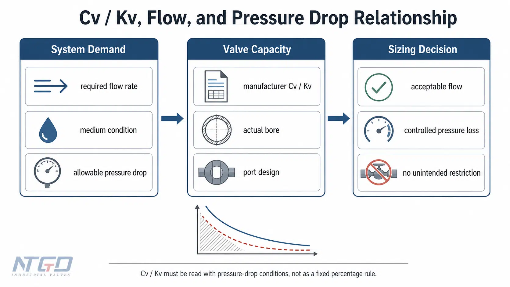
Cv and Kv describe a valve’s flow capacity under defined pressure-drop conditions. They should be used to check whether the valve can pass the required flow within the allowable pressure drop.
Avoid treating Cv as a simple percentage of system flow. Cv/Kv must be interpreted with the service fluid, pressure drop, bore design, and manufacturer data. For critical service, compare required flow, allowable pressure drop, medium condition, and selected port route against the actual valve data sheet.
Pressure-temperature ratings also need confirmation. A valve body may be suitable for one pressure at ambient temperature but derated at higher temperature. Seat and seal materials may have narrower limits than the metal body. If the required Cv/Kv, pressure-temperature rating, or seat/seal limits are not clear, they should be confirmed before RFQ finalization or engineering approval.
NPS, DN, Actual Bore, and Port Design: Why Nominal Size Is Not Enough
Many sizing mistakes happen because users treat nominal size as actual flow capacity. In ball valves, that is a serious oversimplification.
NPS / DN vs Actual Bore and Port Diameter
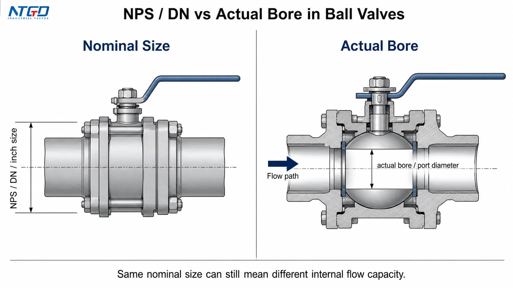
NPS and DN are nominal designations. They help identify pipe and valve size, but they do not always equal the actual internal opening through the ball.
A DN50 or 2-inch ball valve does not automatically have a 2-inch flow path. The actual bore depends on valve design. Full port and reduced port valves may both connect to the same pipe size while offering different internal flow areas.
| Term | What It Means | Why It Matters |
|---|---|---|
| NPS | Nominal Pipe Size | Common inch-based pipe and valve designation |
| DN | Diameter Nominal | Metric nominal designation |
| Actual bore | Real internal opening through the valve | Directly affects flow path, velocity, and pressure drop |
| Port design | Full port, reduced port, V-port, or another bore route | Determines practical flow capacity and application fit |
| Cv / Kv | Flow coefficient | Indicates capacity under defined pressure-drop conditions |
Full Port vs Reduced Port Ball Valves
A full port ball valve has an internal bore close to the pipe bore. It reduces flow restriction and is often preferred when pressure drop must stay low, when the line requires pigging, or when the medium is viscous, abrasive, or sensitive to accumulation.
A reduced port ball valve has a smaller internal bore than the pipe. It can be suitable for many clean services where moderate pressure drop is acceptable and cost or space is a factor. The risk comes when a reduced port valve is selected only because the nominal size matches the pipe, without checking required flow capacity.
| Port Type | Typical Advantage | Typical Limitation | Best-Fit Use |
|---|---|---|---|
| Full port | Larger flow path and lower restriction | Larger body, higher cost, and possible torque / actuator impact | High-flow, low-pressure-drop, pigging, viscous, slurry, or solid-sensitive service |
| Reduced port | Compact design and lower cost | Higher velocity and greater pressure drop than full port | Clean on/off service where some restriction is acceptable and no pigging or solid-sensitive flow is required |
| V-port | More defined flow profile than a standard round port | Not a simple substitute for standard on/off sizing | Modulating or control-oriented service that needs separate control-performance review |
V-Port Ball Valves and Control-Service Boundary
A V-port ball valve is used when the flow profile must be controlled more precisely than a standard round-port ball valve allows. It may help in throttling or modulating service, but it also introduces control profile, actuator sizing, and repeatability questions.
For a standard on/off ball valve sizing article, V-port should remain a boundary topic. If the process requires frequent modulation, the valve should be reviewed as a control-service valve, not selected only by nominal pipe size.
Cv / Kv, Flow Capacity, and Pressure Drop
Cv and Kv values are practical tools for comparing flow capacity. They should be reviewed together with:
- required flow rate,
- allowable pressure drop,
- medium type and density,
- viscosity,
- port design,
- pressure and temperature,
- manufacturer performance data.
A higher Cv/Kv normally indicates higher flow capacity under comparable conditions, but the value is not meaningful without the pressure-drop context. A valve with the same NPS but a smaller bore may have a lower Cv/Kv than a full port valve.
Matching Ball Valve Size to Industrial Service Conditions
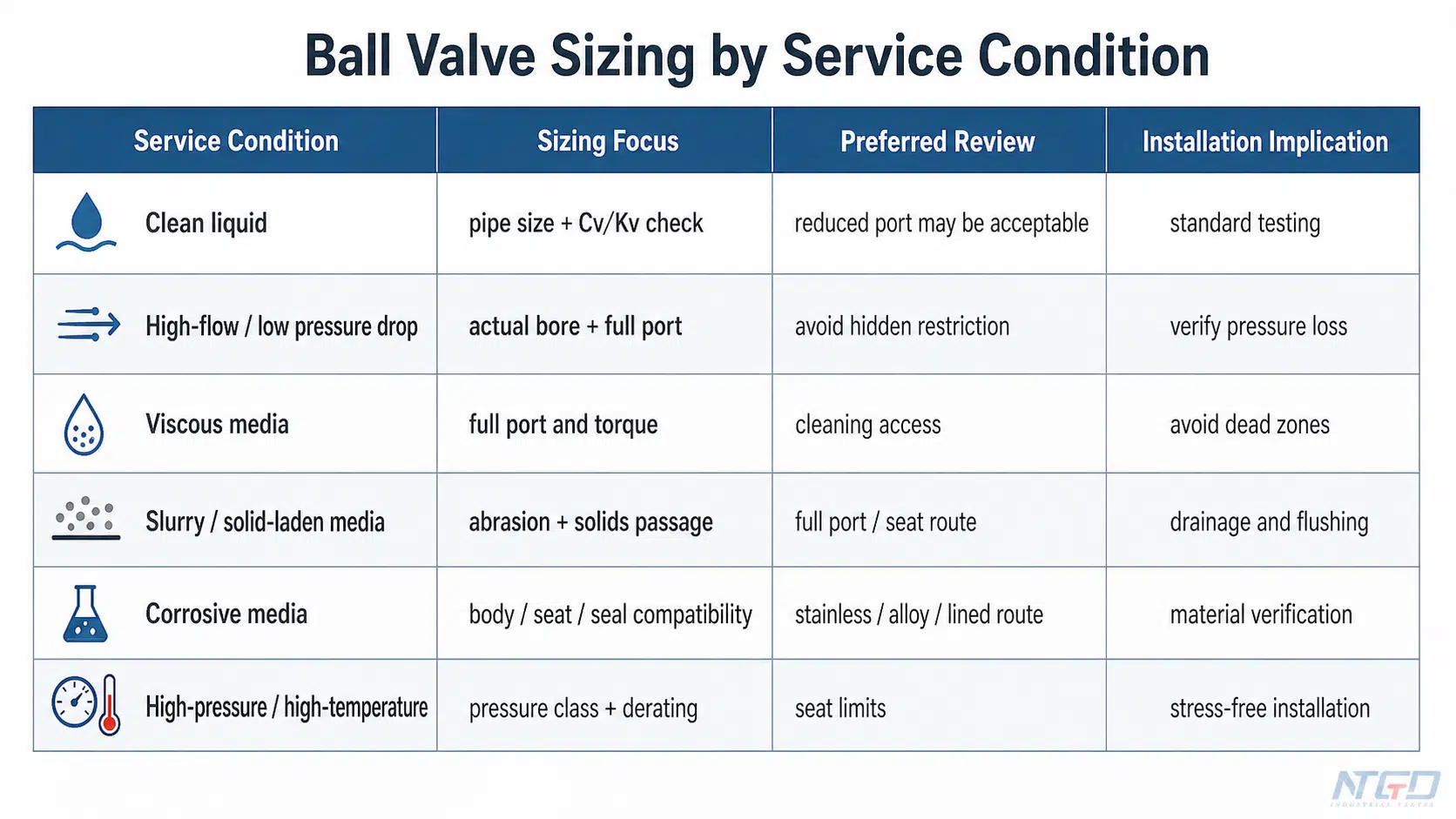
Industrial ball valve sizing becomes reliable when service conditions are mapped directly to port design, bore size, Cv/Kv, material route, seat/seal selection, and installation constraints. The same nominal valve size can behave very differently in clean liquid, viscous media, slurry service, corrosive service, or high-temperature operation.
Clean Liquid and General On/Off Service
For clean liquid service with stable pressure and moderate flow demand, the valve size may follow the pipe size if the selected port design and Cv/Kv meet the flow requirement. A reduced port valve may be acceptable when pressure drop is not critical.
Even in clean service, the final selection should confirm end connection, pressure class, seat material, and installation accessibility. A clean medium does not remove the need for leak testing or cycle testing after installation.
High-Flow or Low-Pressure-Drop Service
When the system requires high flow or low pressure loss, a full port ball valve is often the safer route. This is especially important when the valve remains fully open for long operating periods and should not become a line restriction.
The decision should focus on actual bore, Cv/Kv, and allowable pressure drop rather than nominal size alone. If the system cannot tolerate added pressure loss, a reduced port design should not be accepted without checking actual flow capacity.
Viscous, Slurry, or Solid-Laden Media
Viscous media and fluids with suspended solids are more sensitive to restrictions and internal accumulation. A reduced bore may increase velocity, create localized wear, or make cleaning more difficult.
For a ball valve for slurry applications, the sizing review should check:
- full port availability,
- abrasion risk,
- seat and seal route,
- body material,
- cleaning or flushing requirements,
- possible torque increase from viscous media,
- installation orientation and drainage.
The installation review should also consider drainage, cleaning access, no-stress alignment, and whether the valve orientation could leave solids or viscous media trapped in areas that are difficult to flush.
High-Pressure, High-Temperature, or Corrosive Service
Pressure, temperature, and chemical compatibility can override simple size selection. A valve may fit the pipe and meet the flow requirement but still be unsuitable if the body, seat, seal, stem, or end connection cannot tolerate the service.
High temperature may limit soft seat options. For ball valves in chemical applications, corrosive media may require stainless steel, alloy material, lined construction, or special seat and seal selection. High pressure may require a higher pressure class, stronger body design, and careful control of installation stress.
Material, Seat, and Seal Compatibility
Material selection should not be reduced to one seat material table. For industrial ball valves, compatibility should be reviewed in layers:
| Component Area | What to Check |
|---|---|
| Body material | Corrosion resistance, pressure class, temperature range, and service compatibility |
| Ball and stem | Wear, corrosion, operating torque, coating or surface requirements |
| Seat material | Shutoff performance, temperature capability, abrasion resistance, and chemical resistance |
| Seal material | Leakage prevention, temperature range, and chemical compatibility |
| End connection | Pressure class, gasket or seal route, installation method, and inspection access |
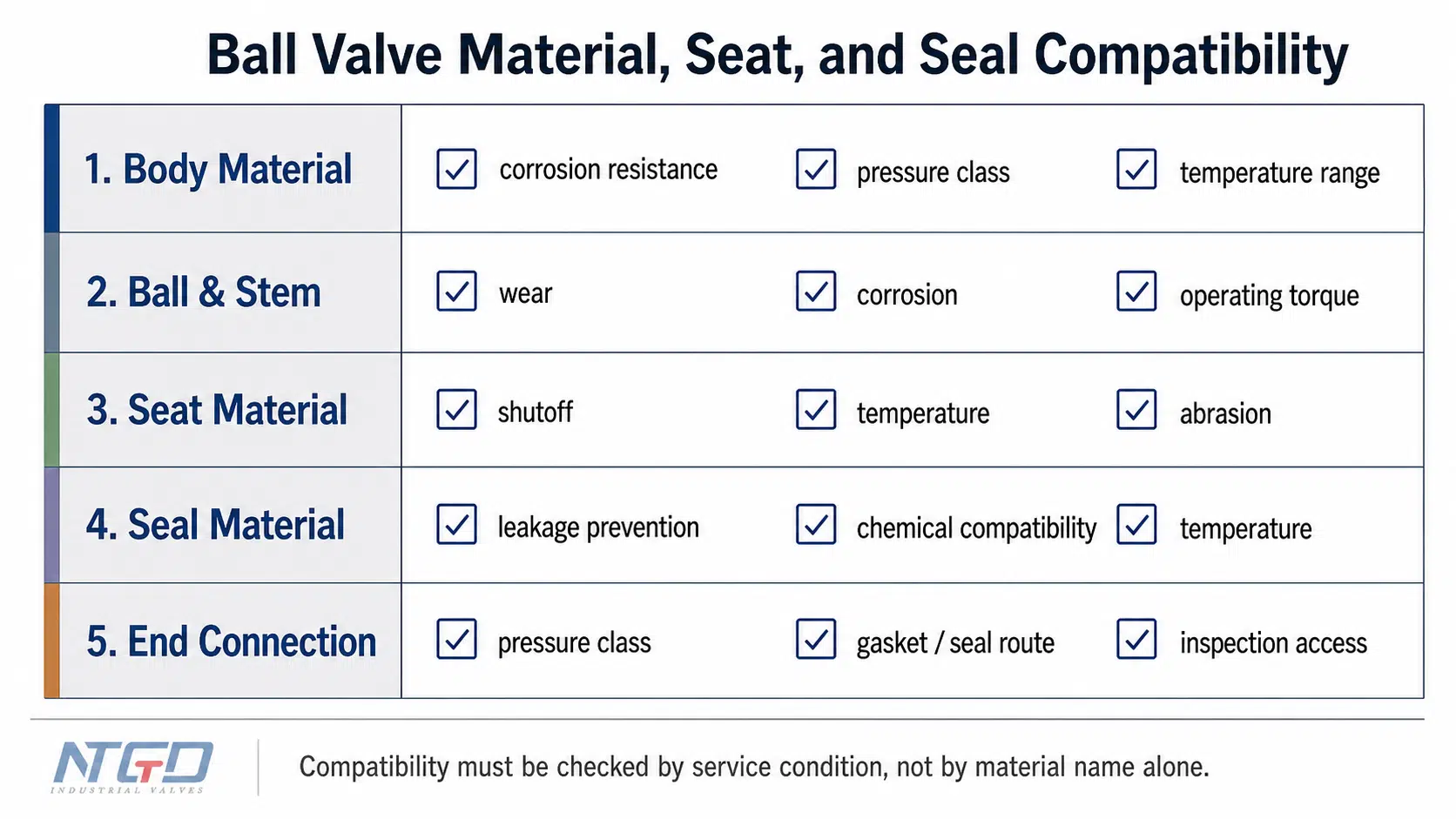
PTFE vs PEEK ball valve seats, elastomeric seals, metal seats, and other routes may be suitable in different services. The correct option depends on chemical compatibility, temperature, pressure, solids, shutoff requirement, and maintenance conditions.
From Correct Sizing to Correct Installation
Installation is where the sizing decision meets the physical pipeline. A correctly selected valve can still fail if the site installation adds body stress, distorts the connection, blocks operation, or leaves the valve untested before commissioning.
Why Installation Should Follow the Sizing Decision
Installation should not be treated as a separate checklist that starts after the valve arrives. It is part of the specification.
Before purchase or installation, each installation condition should protect one part of the sizing decision:
- End connection type protects the selected pressure class and sealing method.
- Face-to-face length or installation length protects dimensional fit and piping layout.
- Flange rating or thread standard protects connection compatibility.
- Gasket or seal method protects leakage performance under the selected medium and pressure.
- Actuator or handle clearance protects operation after the valve is installed.
- Pipe support and alignment protect the valve body, seats, and connections from external stress.
- Flow direction requirements protect special designs such as V-port, vented ball, drain port, or cavity-relief configurations.
- Testing requirements confirm that the valve performs as specified after installation.
This keeps the selected valve aligned with the real pipeline instead of treating sizing as a paper exercise.
Connection Type and Fitting Compatibility
Ball valve fitting and connection compatibility affect both performance and leakage risk. A flanged valve needs the correct flange class, gasket type, bolt condition, tightening sequence, and face alignment. A threaded valve needs compatible threads, proper sealant, and controlled tightening. A welded valve requires welding procedure control and protection of internal seats and seals from heat or debris.
| Connection Route | Key Installation Check | Main Risk if Ignored |
|---|---|---|
| Threaded | Thread compatibility, sealant, controlled tightening | Leakage, thread damage, or body stress from overtightening |
| Flanged | Flange class, gasket, bolt sequence, face alignment | Uneven gasket compression, flange stress, or leakage during pressure testing |
| Welded | Weld procedure, heat control, internal cleanliness | Seat damage, weld contamination, or internal obstruction |
| Compression / specialty fitting | Manufacturer compatibility and pressure limits | Pressure-rating mismatch, joint leakage, or unsuitable service rating |
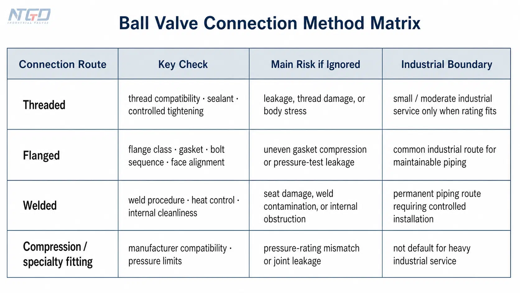
For industrial systems, threaded, flanged, and welded routes should receive priority. Push-to-connect or residential-style fittings may appear in search results, but they should not drive the specification for industrial ball valves.
Installation Direction and Ball Valve Orientation
Many standard two-way ball valves are bidirectional when fully open or closed. However, not every ball valve should be treated as direction-free.
Check the manufacturer’s marking and documentation when the valve has:
- V-port design,
- vented ball,
- drain port,
- cavity relief feature,
- seat design with preferred pressure direction,
- special actuation or flow control function.
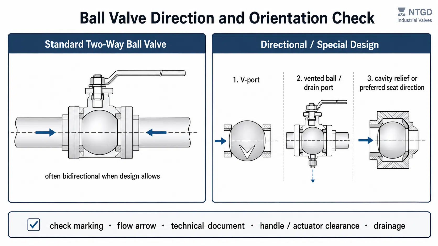
Orientation also includes handle, stem, and actuator accessibility. The valve should be installed where operators can see the open/closed position, operate the handle or actuator safely, and access the valve for inspection.
Alignment, Pipe Support, and Actuator Clearance
A ball valve should not be used to pull misaligned piping into position. Pipe stress can distort the valve body, affect sealing, damage gaskets, or increase operating torque.
Before final tightening, check that:
- the valve and pipe centerlines are aligned,
- the valve is not carrying unsupported pipe weight,
- the actuator or handle has full movement clearance,
- the valve can be cycled without obstruction,
- nearby equipment does not block maintenance access.
Industrial Ball Valve Installation and Acceptance Checks
A ball valve installation guide for industrial service should focus on connection integrity, sealing, alignment, pressure testing, and commissioning. The goal is not only to install the valve, but to confirm that the selected valve performs as specified.
Threaded, Flanged, and Welded Installation Routes
For threaded ball valves, use compatible threads and apply sealant carefully. Excessive sealant can enter the valve and affect sealing. Overtightening can damage threads or stress the valve body.
For flanged ball valves, check flange rating, gasket compatibility, bolt condition, and alignment. Bolted flange joint assembly should use a controlled tightening sequence to compress the gasket evenly.
For welded ball valves, protect internal seats and seals from weld heat and debris. The valve should be clean before commissioning, and the installation should follow the project’s welding and inspection requirements.
Sealant, Gasket, Tightening, and No-Stress Installation
Installation quality often fails at the connection. The correct sealant, gasket, and tightening method depend on the connection type and service.
| Installation Point | What to Check |
|---|---|
| Sealant | Compatible with medium, pressure, and temperature; applied without contaminating the valve internals |
| Gasket | Correct material, size, pressure class, and flange type for the selected service |
| Thread tightening | Tight enough to seal without stressing the body or damaging threads |
| Flange bolting | Even tightening sequence and correct bolt condition for uniform gasket compression |
| Pipe support | Valve is not carrying pipe weight or external load |
| Alignment | No forced fit between pipe and valve centerlines |
Leak Test, Pressure Test, and Cycle Test
After installation, test the valve before full operation. A visual inspection alone is not enough for industrial service.
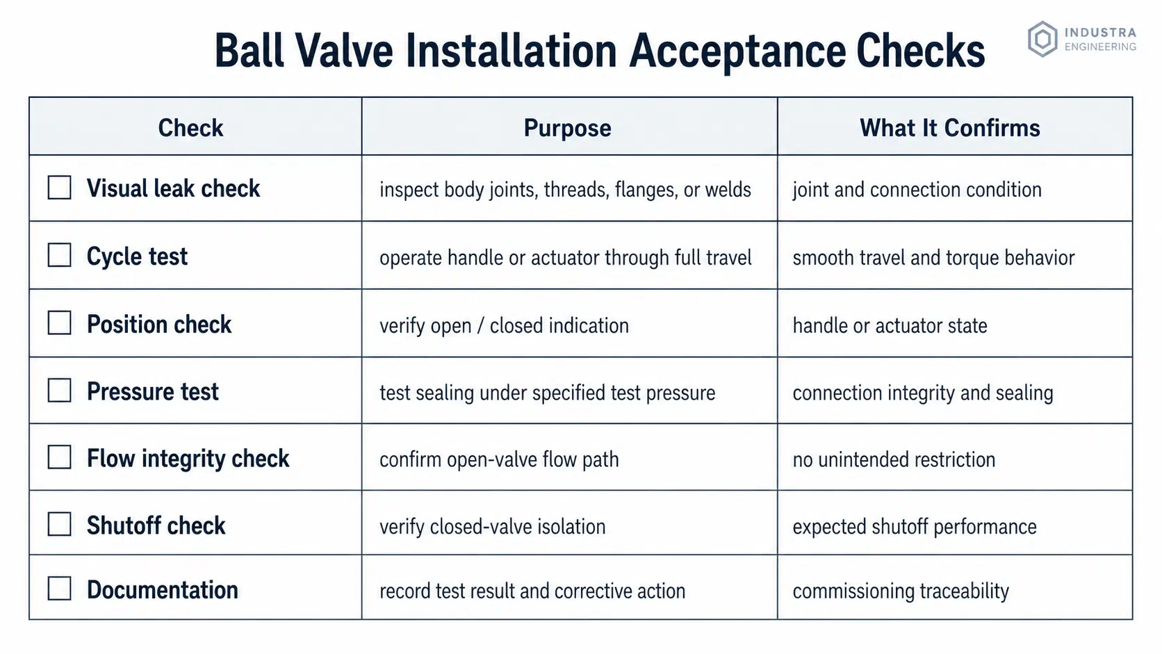
A practical valve inspection and testing sequence should include:
| Test / Check | Purpose |
|---|---|
| Visual leak check | Identifies obvious leakage around body joints, threaded areas, flanges, or welded connections |
| Handle or actuator cycle test | Confirms smooth travel and helps detect torque problems, actuator mismatch, or internal obstruction |
| Position check | Confirms that handle or actuator position matches the actual open / closed state |
| Pressure test | Verifies connection integrity, gasket compression, body stress condition, and sealing under test pressure |
| Flow integrity check | Confirms that the valve passes expected flow when open and does not behave like an unintended restriction |
| Shutoff check | Confirms expected isolation when closed and helps detect seat or seal problems |
| Documentation | Records test results for commissioning, maintenance traceability, and later troubleshooting |
A failed pressure test is not only a leakage event. It may point to incorrect gasket selection, uneven bolt tightening, connection damage, or body stress from misalignment. A failed cycle test may indicate actuator undersizing, internal obstruction, excessive pipe stress, or incorrect installation clearance.
Documentation and Final Commissioning Check
Documenting installation and test results helps maintenance teams trace later problems. The record should include valve tag number, size, pressure class, connection type, test pressure, leakage observation, actuator condition, and corrective actions.
If the valve shows unusual torque, leakage, pressure drop, or handle misalignment during commissioning, do not treat it as a minor issue. These symptoms may indicate wrong sizing, poor alignment, incorrect connection assembly, or internal damage.
Common Sizing and Installation Mistakes to Avoid
Sizing and installation mistakes often compound each other. A marginal sizing decision becomes worse when the valve is misaligned or poorly tested. A correct sizing decision can still fail when the installation adds pipe stress or damages the sealing interface.
Choosing Size by Pipe Size Only
Pipe size is not the same as ball valve flow capacity. A reduced port valve may connect to the same pipe as a full port valve but restrict more flow.
The first sign of this mistake is often an unexpected pressure drop during peak demand. Teams may investigate pumps or downstream equipment while the real restriction is inside a reduced-port valve that looked correct on the specification sheet.
Ignoring Cv / Kv, Pressure Drop, or Port Type
A valve should not be selected only from a dimensional chart. Cv/Kv and port design help confirm whether the valve can pass the required flow under the allowable pressure drop.
When this check is skipped, the system may show high velocity, noise, unstable flow, or reduced downstream performance. The valve may be dimensionally correct but hydraulically wrong.
Using the Wrong Material, Seat, or Pressure Rating
A valve that fits the pipe may still be wrong for the medium. Chemical attack, temperature limits, abrasion, and pressure-temperature derating can all affect service life.
The failure path is usually gradual at first: seat damage, ball valve leakage, corrosion marks, abnormal torque, or repeated maintenance. In severe service, a wrong material route can lead to early shutdown or replacement even when the valve size is correct.
Poor Alignment, Overtightening, or Unsupported Piping
Misalignment loads the valve body and connections. Overtightening threaded valves can damage threads or stress the body. Unsupported piping can transfer weight and vibration into the valve.
These conditions may appear during installation as difficult tightening, uneven flange gaps, high operating torque, gasket leakage, or poor handle movement. If not corrected, they can shorten valve life and make future maintenance more difficult.
Skipping Post-Installation Testing
Skipping leak, pressure, and cycle testing leaves the system unverified. Small connection leaks, unusual torque, handle misalignment, or pressure loss may not appear until startup.
Testing before commissioning is less costly than troubleshooting a failed valve after the system is in operation. It also confirms whether the sizing decision, connection method, and installation quality work together as intended.
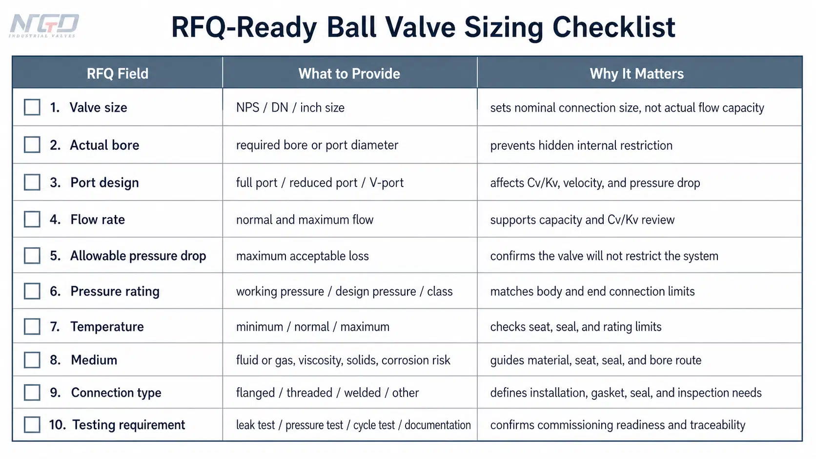
RFQ-Ready Ball Valve Sizing and Installation Checklist
A useful ball valve RFQ should follow broader industrial valve selection criteria by giving the supplier enough information to confirm size, port design, pressure rating, material, connection, and installation constraints. “2-inch ball valve” is not enough for an industrial specification.
| RFQ Field | What to Provide | Why It Matters |
|---|---|---|
| Valve size | NPS / DN / inch size | Establishes nominal connection size, but does not confirm actual flow capacity |
| Actual bore requirement | Full port, reduced port, V-port, or required bore | Prevents supplier assumptions about the internal flow path |
| Flow rate | Normal and maximum flow | Supports Cv/Kv review and confirms whether the valve can meet demand |
| Allowable pressure drop | Maximum acceptable loss across the valve | Helps confirm that the selected port and Cv/Kv will not create hidden restriction |
| Pressure rating | Working pressure, design pressure, pressure class | Confirms body, end connection, and pressure-temperature suitability |
| Temperature | Minimum, normal, and maximum | Affects seat, seal, body material, and rating limits |
| Medium | Fluid or gas, viscosity, solids, corrosion risk | Determines material, seat, seal, bore route, and cleaning considerations |
| Material route | Body, ball, stem, seat, and seal preferences | Prevents compatibility failures and avoids unsuitable seat or seal assumptions |
| Connection type | Flanged, threaded, welded, or other | Determines installation method, gasket or seal route, and inspection requirements |
| Operation | Lever, gear, pneumatic, electric, or other actuation | Affects torque, clearance, support, and commissioning checks |
| Installation orientation | Space, access, flow direction, support requirements | Prevents field conflicts that can invalidate a correct sizing decision |
| Testing requirement | Leak test, pressure test, cycle test, documentation | Confirms commissioning readiness and provides maintenance traceability |
When the service is high-flow, corrosive, high-temperature, slurry, viscous, or pressure-sensitive, confirm sizing with actual Cv/Kv data and service conditions before final purchase.
FAQ
How do I know if a ball valve is the right size for my line?
Start with the pipe’s nominal size, but do not stop there. Check the actual bore, port type, required flow rate, allowable pressure drop, end connection, and manufacturer Cv/Kv data. A valve can match the pipe size and still restrict flow if it is a reduced-port design or if the Cv/Kv is too low for the service.
What does ball valve size in mm mean?
Ball valve size in mm usually refers to a metric nominal designation, often expressed as DN. DN helps match the valve to the pipe system, but it should not be treated as the exact internal bore. Check the valve drawing or manufacturer dimensions for actual port size and connection details.
Should I check flow direction before installing a ball valve?
Yes. Many standard two-way ball valves are bidirectional, but some designs are not. V-port balls, vented balls, drain ports, cavity relief features, or special seat designs may have a preferred direction. Always check the marking or technical document before installation.
Does ball valve orientation matter?
Yes. Even when flow direction is not critical, orientation can affect drainage, handle access, actuator clearance, operation visibility, and maintenance. The valve should be installed so it can be operated safely, inspected easily, and supported without pipe stress.
What is the correct ball valve installation direction?
For a standard two-way ball valve, installation may be bidirectional. For special designs, follow the flow arrow, body marking, or manufacturer instruction. In every case, align the valve with the pipe, avoid forced fit, and confirm that the open / closed position is visible after installation.
How do you install a ball valve after sizing it?
After sizing, confirm the connection type, pressure class, gasket or seal route, alignment, and installation space. Install the valve without forcing the pipe into position, use the correct sealant or gasket, tighten connections properly, cycle the valve, and perform leak and pressure testing before commissioning.
Does full port or reduced port affect ball valve sizing?
Yes. A full port ball valve usually provides a larger internal flow path and lower pressure drop. A reduced port ball valve has a smaller bore, which may be acceptable in clean service but can restrict flow in high-flow, viscous, or solid-laden applications. The choice should follow flow rate, allowable pressure drop, medium, and service conditions.
Conclusion
Proper ball valve sizing starts with system data and ends with installation verification. Pipe size is only the starting point. Final selection should confirm flow rate, allowable pressure drop, Cv/Kv, NPS or DN, actual bore, port design, pressure class, material compatibility, connection type, and installation requirements.
A well-sized valve can still fail if it is installed with poor alignment, unsupported piping, overtightened connections, or no pressure test. A well-installed valve can still restrict the system if the bore, Cv/Kv, or material route is wrong. Treat sizing and installation as one engineering sequence: define the service, select the correct valve configuration, install it without stress, and verify performance before commissioning.
Final Application Check
Before final RFQ confirmation, NTGD Valve can support a technical review of ball valve bore route, Cv/Kv suitability, pressure drop, material compatibility, connection type, and installation requirements for demanding industrial services such as high-flow, corrosive, slurry, high-pressure, or pressure-sensitive applications.
