
Имя автора: Брюс Чжэн
Роль автора: Соучредитель и инженер по клапанам в NTGD Valve
Био автора: Брюс Чжэн - соучредитель и инженер по клапанам в компании NTGD Valve, специализирующейся на выборе промышленных клапанов, их применении и техническом контенте для глобальных покупателей B2B.
Последнее обновление: 17 июня 2026 года
Монтаж задвижки напрямую влияет на надежность уплотнения, доступность для обслуживания, риски при вводе в эксплуатацию, будущее техническое обслуживание и долгосрочную работоспособность трубопроводной системы. В промышленных трубопроводных системах в процессе монтажа необходимо убедиться в соответствии клапана техническим условиям, требованиям к направлению потока, ориентации установки, зазору штока, опоре трубы, выравниванию фланцев, затяжке болтов, состоянию прокладок, наличию пространства для эксплуатации и требованиям к вводу в эксплуатацию до того, как клапан будет введён в эксплуатацию.
Данное руководство по монтажу задвижек составлено для стандартных промышленных задвижек, используемых в целях изоляции. Оно призвано помочь инженерам, монтажникам, специалистам по техническому обслуживанию и закупщикам проектов разобраться в основных контрольных мероприятиях, которые необходимо выполнить до и после монтажа.
Информацию о настройке на уровне продукта перед проверкой установки см. в документации NTGD промышленные задвижки определить диапазон и согласовать окончательную спецификацию с проектной документацией.
Данный документ не заменяет руководство по эксплуатации и техническому обслуживанию (IOM) производителя, проектную документацию, эксплуатационные инструкции, применимые стандарты или требования безопасности, специфичные для данного проекта. Точные пределы установки зависят от конструкции клапана, класса давления, материала, типа торцевого соединения, условий эксплуатации, способа крепления привода и схемы прокладки трубопровода.
Краткий ответ: Как следует устанавливать задвижку?
Задвижку следует устанавливать только после проверки соответствия клапана, трубопровода, прокладок, болтовых соединений, требований к направлению потока, ориентации при монтаже и рабочего зазора в соответствии с руководством по эксплуатации, техническим паспортом и проектным чертежом. При обращении с задвижкой следует избегать повреждения корпуса, штока, фланцевых поверхностей, уплотнительных зон или привода. Трубопровод должен быть чистым, выровненным и надлежащим образом закрепленным, чтобы корпус задвижки не использовался для корректировки перекоса трубы или переноса внешней нагрузки на трубу.
For most industrial gate valve installation procedures, confirm the valve tag, size, pressure class, material, end connection, and service suitability before installation. The valve should then be positioned correctly, aligned with the pipe, fitted with the correct gasket or end preparation, tightened according to the specified procedure, operated through an open-close check, and verified during pressure or leakage testing as required by the project.
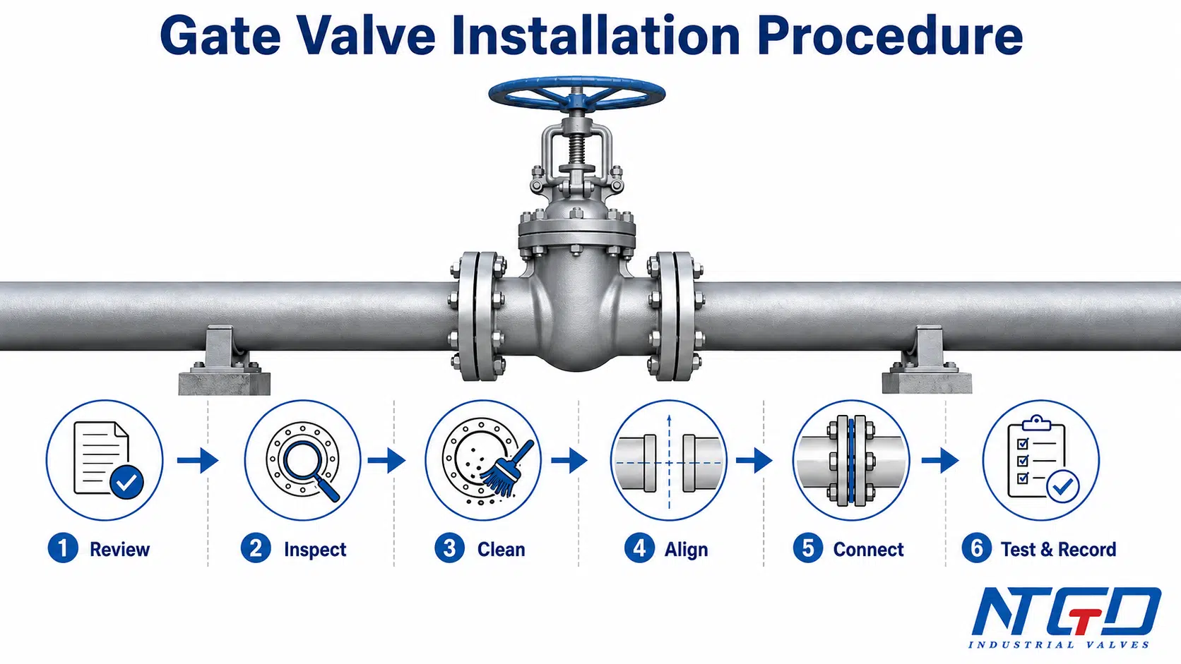
Краткое руководство по промышленной установке
| Шаг | Check | Почему это важно | Избегайте |
|---|---|---|---|
| 1 | Review the IOM, datasheet, and project drawing | Confirms valve limits, direction notes, end connection, and installation conditions | Installing only by visual appearance |
| 2 | Confirm valve tag, size, class, material, and connection | Prevents wrong valve placement in the piping system | Mixing valves with similar dimensions but different ratings |
| 3 | Inspect the valve before installation | Detects transit damage, flange face damage, stem issues, or missing accessories | Installing a damaged valve and discovering leakage later |
| 4 | Clean the pipeline | Removes welding slag, rust, dirt, or debris that can damage the seat area | Using the valve as a debris trap |
| 5 | Verify flow direction requirements | Prevents incorrect installation where a body arrow, special design, accessory arrangement, or project drawing defines direction | Skipping the IOM, body marking, or project drawing check |
| 6 | Confirm installation orientation and stem clearance | Ensures operation access, stem travel, drainage, and maintenance space | Installing stem-down or blocking handwheel / actuator access |
| 7 | Align the pipe and support the valve correctly | Prevents body strain, flange leakage, and high operating torque | Pulling misaligned pipe into position with flange bolts |
| 8 | Install gaskets and bolting according to the IOM | Maintains sealing integrity at the end connection | Using incorrect gaskets or uncontrolled tightening |
| 9 | Perform operation and commissioning checks | Verifies open-close movement, leakage status, and installation records | Starting service without functional confirmation |
Что охватывает данное руководство и что оно не заменяет
This article covers the main engineering checks for gate valve installation in industrial piping systems. It focuses on installation procedure, orientation, support, alignment, bolting, operation check, pressure / leakage test review, and commissioning records.
This guide does not replace:
- The valve manufacturer’s IOM.
- The project piping specification.
- The approved installation drawing.
- Applicable pressure testing or safety standards.
- Site-specific lifting, welding, flushing, and commissioning procedures.
- Requirements for special service such as cryogenic, steam, buried service, severe corrosion, or high-pressure operation.
For an external valve-user reference, MSS SP-92 is organized around selection, shipping and storage, installation, and operation and maintenance; use the MSS SP-92 valve user guide preview only as a general reference, not as a substitute for the manufacturer’s IOM.
Skipping the IOM, project drawing, or site procedure in an industrial project can lead to the wrong installation orientation, incorrect connection details, leakage, failed testing, rework, and commissioning delay.
This article also does not cover knife gate valve installation as a main topic. Knife gate valves may have different seat-side, slurry, pressure direction, and orientation requirements, so they should be reviewed separately.
Перед монтажом ознакомьтесь с инструкцией по эксплуатации, техническим паспортом и проектными чертежами
Before installing a gate valve, verify the installation requirements from the IOM, datasheet, project drawing, and purchase specification. This step is especially important when multiple valves on the project have similar face-to-face dimensions but different pressure classes, materials, end connections, trims, or actuation arrangements.
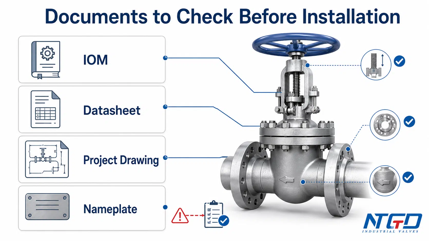
A gate valve manual or IOM may include information about preferred orientation, lifting points, flow arrow markings, lubrication, bolting, gasket requirements, storage protection, operation checks, and testing limitations. The project drawing may also define the valve tag number, installation location, pipe orientation, access direction, support arrangement, and required position in the system.
Уточните размер клапана, класс давления, материал и тип торцевого соединения
The first installation check is to confirm that the valve matches the line list and project drawing. A gate valve should not be installed only because it physically fits the pipe. The valve must match the required size, pressure class, body material, trim or seat design, end connection, operation method, and service condition.
| Document / Marking | Что проверить | Почему это важно |
|---|---|---|
| Nameplate or body marking | Size, pressure rating, material, heat number or tag if applicable | Confirms the valve matches the project requirement |
| Информационный лист | Material, pressure class, end connection, operation type, trim / seat information | Prevents installation of a valve with the wrong specification |
| Project drawing | Valve tag, flow direction note, orientation note, access space, support location | Confirms where and how the valve should be installed |
| МОМ | Handling, installation, bolting, testing, operation, and maintenance notes | Prevents avoidable installation damage |
| Purchase specification | Service condition, testing requirement, special accessories | Confirms project-specific expectations |
When API compliance or test documentation is part of the project, review NTGD’s Стандарты API для задвижек guide before finalizing the IOM and test package.
For ductile iron, resilient wedge, OS&Y, API 600, or other product-specific gate valves, the installation check should still start with the project specification and the manufacturer’s documentation. Product type helps frame the application, but it does not define the complete installation procedure by itself.
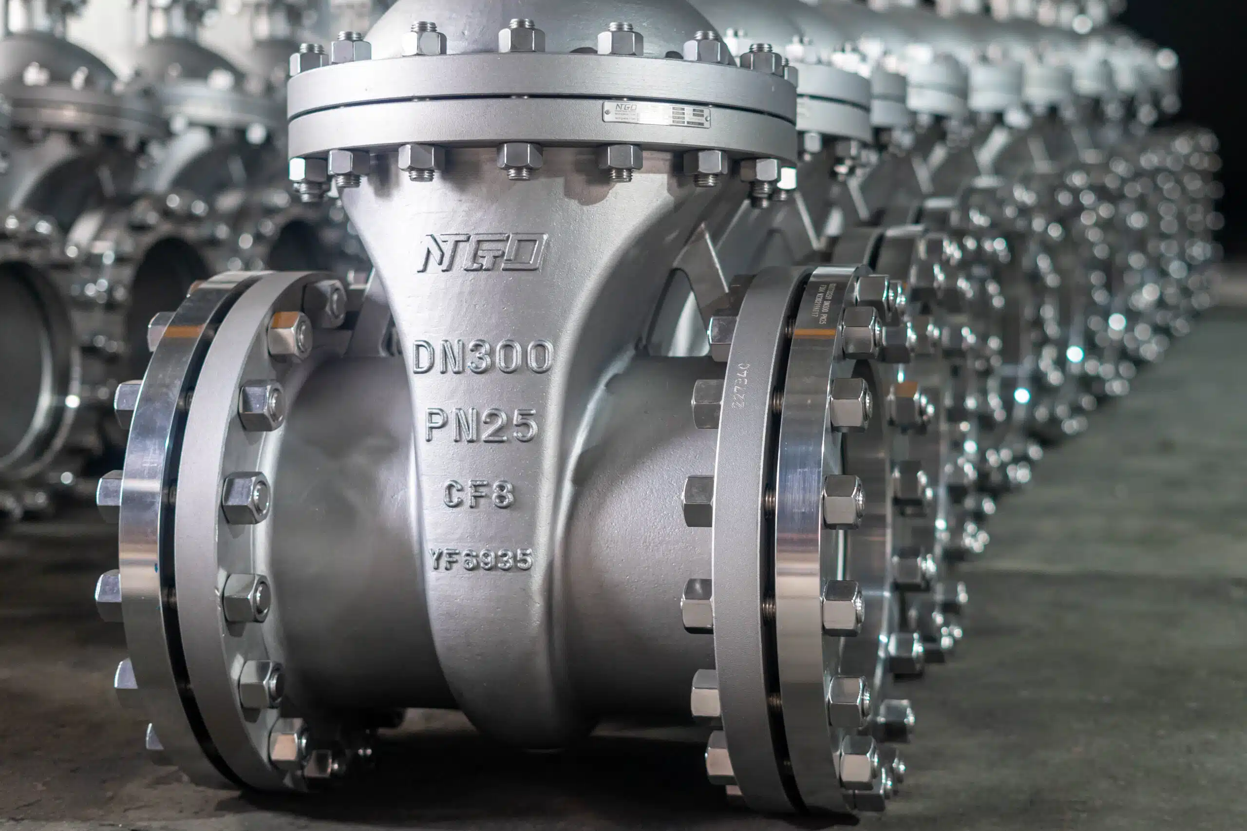
Ознакомьтесь с инструкциями по монтажу, маркировкой на корпусе и особыми требованиями к конструкции
Many standard gate valves are used as isolation valves and may be installed in a relatively straightforward manner when the IOM allows it. However, some designs, accessories, bypass arrangements, drain connections, pressure relief features, or body markings may require special attention.
If a body arrow, “INLET” marking, “SEAT” marking, pressure direction marking, or special flow note is present, it should be checked before installation. The presence of a marking should not be ignored, and the absence of a marking should not be treated as permission to skip the IOM.
Special design requirements may also apply to:
- Pressure seal bonnet gate valves.
- Rising stem or OS&Y designs with long stem travel.
- Gear-operated or actuated gate valves.
- Valves with bypass lines, drains, vents, or limit switches.
- High-pressure, high-temperature, corrosive, or severe-service installations.
- Buried or underground service where access is limited after installation.
Проверьте доступ, ход штока и зазор привода
A gate valve must be installed where it can be operated, inspected, and maintained. This is especially important for rising stem, OS&Y, gear-operated, or actuated gate valves.
Before final positioning, verify sufficient clearance for:
- Handwheel rotation.
- Stem travel.
- Gearbox or actuator removal.
- Limit switch access.
- Packing adjustment access.
- Bonnet inspection.
- Future maintenance or replacement.
If the valve is installed too close to a wall, floor, platform, pipe rack, support, insulation, or adjacent equipment, operation and maintenance may become difficult even if the valve itself was installed correctly.
Контрольный список для проверки перед монтажом
Pre-installation inspection helps catch problems before the valve is fixed into the piping system. Once a gate valve is installed, access to flange faces, sealing areas, body markings, and internal cleanliness becomes more limited.
The inspection should be practical and focused. The goal is not to turn the installation guide into a full parts guide, but to confirm that the valve can be safely installed without obvious damage, mismatch, or contamination.
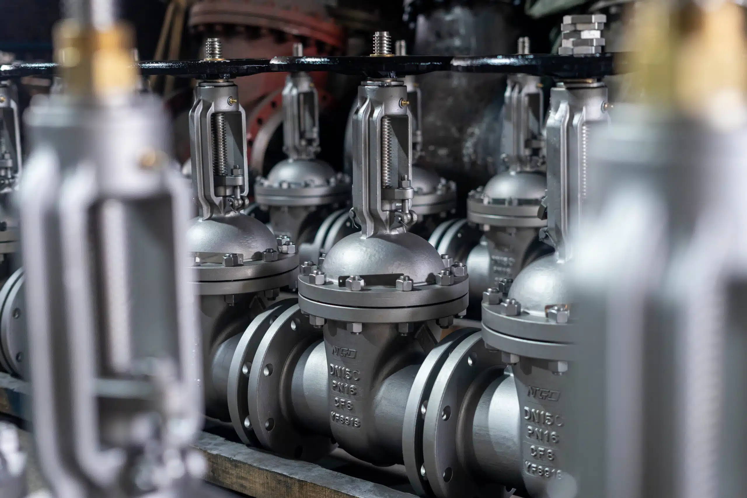
Осмотрите корпус клапана, шток, клиновидный элемент, зону седла и торцевые поверхности фланцев
| Артикул | Место осмотра | Risk If Missed |
|---|---|---|
| Корпус клапана | Check for visible cracks, impact damage, casting defects, or shipping damage | Body leakage, unsafe service condition, or rejection during site inspection |
| Flange faces | Check for scratches, dents, rust, or coating contamination on sealing surfaces | Flange leakage after tightening, repeated gasket replacement, or test delay |
| Стебель | Check visible straightness, threads, cleanliness, and travel condition | High torque, poor operation, packing damage, or blocked commissioning check |
| Маховик / редуктор / привод | Confirm secure mounting and no visible damage | Operation failure after installation or unsafe manual operation |
| Wedge / disc movement | Confirm smooth operation and full stem travel from fully closed to fully open as allowed by the IOM | Sticking, incomplete closure, flow restriction, vibration, seat damage, or incomplete isolation |
| Seat area / bore | Check for foreign material where visible and accessible | Leakage, seat scratching, or early sealing damage |
| Площадь упаковки | Check for visible damage or abnormal looseness | Leakage after pressure test or need for early adjustment |
| Body markings | Confirm flow arrow, pressure class, material, and tag where applicable | Wrong installation direction or wrong valve placement |
If the valve has been stored for a long period, the installer should also check protective covers, internal cleanliness, corrosion protection, and any preservation requirements stated in the IOM.
Проверьте прокладки, болтовые соединения, торцевые соединения и сопутствующие детали
Gaskets and bolting should be suitable for the flange standard, pressure class, temperature, fluid, and project specification. A visually similar gasket may not be suitable for the actual service.
For flanged gate valve installation, check:
- Gasket type and material.
- Gasket size and flange compatibility.
- Bolt and nut material.
- Bolt length and thread engagement.
- Washer requirement if specified.
- Cleanliness of flange faces.
- Correct gasket centering.
- Bolt tightening procedure in the IOM or project specification.
For welded or socket weld end gate valves, the installer should follow the approved welding procedure and take care not to damage the valve seat, stem packing, or internal components through uncontrolled heat input. This article does not replace a welding procedure specification.
For mechanical joint or waterworks-style gate valve installations, the joint components, restraint system, gasket arrangement, and municipal project requirements should be checked against the approved installation standard and project drawing.
Очистите трубопровод и удалите сварочный шлак, ржавчину и мусор
Pipeline cleanliness is one of the most common installation risks. Welding slag, sand, rust, scale, cutting debris, gasket fragments, and construction dirt can damage the seat area or prevent full closure.
Before installation and commissioning, the pipeline should be cleaned according to the project procedure. The valve should not be used as a filter or debris collector. If the system requires flushing, blowing, or cleaning, the valve position and protection method should follow the IOM and project procedure.
Poor debris control may lead to:
- Seat scratching.
- Leakage during pressure test.
- High operating torque.
- Incomplete closure.
- Damage to the wedge or seat ring.
- Early maintenance after startup.
Any of these issues can lead to test failure and delay commissioning, turning a preventable cleaning step into a critical path problem.
Before final alignment and bolting, the installation team should also make a basic check of pipe centerline alignment, flange parallelism, and pipeline alignment. The detailed support and alignment checks are covered later in this guide.
Контрольный список по процедуре монтажа задвижки
A gate valve installation procedure should be treated as a controlled checklist, not as a casual fitting task. The exact procedure depends on the end connection, valve size, pressure class, lifting method, pipeline layout, and site rules, but the core installation logic is similar: confirm, inspect, align, connect, support, operate, test, and record.
The Quick Answer table above gives a high-level procedure summary. The checklist below is an execution-level review for the installation team before final tightening, testing, and commissioning.
| Шаг | Installation Check | Engineering Purpose | Избегайте |
|---|---|---|---|
| 1 | Confirm tag, size, class, material, and end connection | Prevents wrong valve installation and wrong line placement | Installing the wrong valve because it fits the pipe |
| 2 | Review IOM and project drawing | Confirms orientation, access, lifting, testing, and special instructions | Relying only on previous experience |
| 3 | Inspect valve and pipeline ends | Detects damage, dirt, coating contamination, and mismatch | Installing over damaged flange faces |
| 4 | Remove debris and protect sealing areas | Prevents seat scratching, gasket damage, and early leakage | Leaving slag or rust in the line |
| 5 | Lift and position the valve correctly | Prevents body, stem, actuator, or flange damage | Lifting by handwheel, stem, or unsupported actuator |
| 6 | Align the pipe and valve without forcing | Prevents body strain, flange leakage, and high torque | Using bolts to pull misaligned pipe together |
| 7 | Install gasket or prepare weld / joint as specified | Maintains sealing integrity for the selected end connection | Using incorrect gasket or joint components |
| 8 | Tighten bolting according to the IOM or site procedure | Provides controlled compression and reduces uneven gasket loading | Random or uneven tightening |
| 9 | Check operation and stem clearance | Confirms functional readiness: accessibility, smooth full-travel operation, and position indication | Discovering blocked operation after startup |
| 10 | Complete pressure / leak test and records | Confirms installation readiness and traceability | Starting service without documentation |
The video below provides a practical visual reference for flanged gate valve installation on pipework. Always follow the valve manufacturer’s IOM, project drawing and site procedure for the final installation method.
Установите клапан, не прилагая усилия к трубопроводу
The valve should be positioned so that the pipeline and valve ends meet naturally. The valve should not be used to pull the pipe into position, correct angular misalignment, or absorb external pipe stress.
For large gate valves, lifting and handling are critical. The lifting method should protect the valve body, bonnet, stem, handwheel, gearbox, actuator, and flange faces. Lifting points or slings should follow the IOM and site lifting plan.
Improper positioning can cause:
- Flange leakage.
- Body distortion.
- Seat misalignment.
- High operating torque.
- Packing leakage.
- Stress on welded or mechanical joints.
Правильно выровняйте фланцы или торцевые соединения
For flanged gate valves, flange alignment should be checked before gasket installation and final bolting. The flange faces should be parallel, centered, clean, and free from damaging surface defects. The bolt holes should align without forcing the valve or pipe.
For welded gate valves, end preparation, root gap, heat control, and internal protection should follow the approved welding procedure. If the valve must be in a particular position during welding or heat treatment, that requirement should come from the IOM or project procedure.
For mechanical joint gate valves, the joint gasket, gland, bolts, and restraints must be assembled according to the project specification. This type of connection can have application-specific requirements, especially in water pipeline or buried service.
Установите прокладки и затяните болты в соответствии с инструкцией по эксплуатации
Gasket and bolting work should follow the IOM, flange standard, project specification, and site procedure. The goal is controlled compression and even sealing, not simply making the joint “as tight as possible.”
For flanged gate valves, flange and gasket checks should remain tied to the project flange standard; ASME describes ASME B16.5 pipe flanges and flanged fittings as covering pressure-temperature ratings, materials, dimensions, tolerances, marking, testing, flange bolting, gaskets and joints.
A practical pre-installation check should cover:
- Correct gasket type and size.
- Correct bolt grade and length.
- Clean flange faces.
- Gasket centered before tightening.
- Bolting tightened in a controlled cross-pattern where specified.
- Final inspection after tightening.
Over-tightening, uneven tightening, damaged gaskets, or dirty flange faces can lead to leakage even when the valve itself is in good condition. The exact tightening method and torque value should always be verified from the project specification or manufacturer’s documentation.
Обеспечьте защиту клапана во время сварки, нанесения покрытия или проведения работ на объекте
After installation, the valve may still be exposed to site work such as welding nearby pipe, coating, insulation, hydrostatic testing, flushing, scaffolding, or equipment movement. The valve should be protected from weld spatter, paint overspray, dust, impact, and debris.
Protective covers should not be removed too early if the internal area may be exposed to dirt. At the same time, any temporary protection must be removed before commissioning if it could block operation, drainage, venting, or inspection.
Ориентация задвижки и положение штока
Gate valve orientation is one of the most important supporting checks in an industrial installation. It affects operation access, stem travel, packing behavior, drainage, maintenance space, actuator support, and future inspection.
For many ordinary gate valves, the preferred installation orientation is with the stem vertical and the handwheel or actuator accessible from above or from a safe operating position. However, the acceptable installation orientation depends on the valve design, line orientation, actuator weight, pipe support, service condition, and the manufacturer’s IOM.
Рекомендуемая ориентация для большинства промышленных установок
In many industrial layouts, a stem-up orientation is preferred when practical because it supports easier operation, clearer position indication for rising stem or OS&Y designs, better access to packing and bonnet areas, and reduced risk of debris settling around the stem or bonnet area.
This does not mean that every gate valve must always be installed only in one position. Some valves may be installed in horizontal or vertical pipelines, and some may allow different stem positions. The final acceptable orientation is determined by the valve’s IOM and project-specific requirements. Confirm actuator support, maintenance access, pipe layout, and stem travel before finalizing the installation position.
| Installation Case | Common Preference | Acceptable When | Avoid / Review Carefully |
|---|---|---|---|
| Horizontal pipeline, stem vertical upward | Часто предпочитают | Access, stem clearance, packing access, and support are available | If overhead space blocks stem travel, actuator removal, or safe operation |
| Horizontal pipeline, stem horizontal | Может быть приемлемо для некоторых конструкций | IOM allows it, the operator is accessible, and the actuator / handwheel is properly supported | If actuator weight creates side load, drainage is poor, or maintenance access is limited |
| Horizontal pipeline, stem downward | Usually avoided unless specifically allowed | Only when manufacturer and project requirements permit, and the risk review is documented | Debris, drainage, packing inspection, lubrication, and long-term maintenance risk |
| Vertical pipeline | Depends on flow, support, and valve design | Valve weight, actuator access, and pipe support are properly managed | Unsupported valve body, inaccessible operator, or uncontrolled actuator load |
| Rising stem / OS&Y valve | Requires stem travel clearance | Space is reserved for the full open position and position indication remains visible | Installing too close to a structure, platform, insulation, or pipe rack |
| Gear-operated or actuated valve | Requires support and access review | Actuator weight, wiring, manual override, and maintenance access are considered | Hanging heavy actuators without support where required |
Примеры монтажа трубопроводов в горизонтальном и вертикальном положении
A gate valve can often be installed in a horizontal pipeline, but the stem position must be reviewed. The most common industrial preference is stem-up when space allows. Horizontal stem installation may be acceptable for some designs, but it should be reviewed against the IOM and support arrangement.
For vertical pipeline installation, the valve body, actuator, and pipe support require special attention. The valve should not impose uncontrolled load on connected piping. The operator should remain accessible and safe to use. If the valve is large, actuated, or installed at height, maintenance access should be reviewed before installation.
The key question is not only “Can the valve fit?” but also:
- Can the valve be operated safely?
- Can the stem travel freely?
- Can the packing and bonnet area be inspected?
- Can the actuator or gearbox be removed later?
- Is the valve body supported correctly?
- Does the installation follow the IOM and project drawing?
Почему обычно стараются избегать монтажа «стеблем вниз» или «вверх ногами»
Stem-down or upside-down installation is usually not recommended for ordinary industrial gate valves unless the manufacturer’s IOM and project specification explicitly allow it. This orientation may create problems with debris accumulation, drainage, access, packing inspection, lubrication, actuator support, or future maintenance.
A valve installed upside down may still physically open and close, but that does not mean the installation is good engineering practice. For industrial service, the risk is not limited to immediate operation. The more important risks are long-term accessibility, seal reliability, maintenance difficulty, and the ability to verify the valve condition after startup.
If a project layout appears to require stem-down installation, the installer should stop and confirm the arrangement with the valve manufacturer or project engineer before installation.
Вопросы, связанные с подъемным и неподъемным штоком, а также зазором OS&Y
Rising stem and OS&Y gate valves need special attention because the stem moves visibly as the valve opens or closes. If the installer does not reserve enough space, the stem may contact a platform, insulation, pipe rack, ceiling, guard, or equipment.
Restricted stem travel can prevent the valve from reaching the full open position, make position indication unreliable, or cause interference between the stem, actuator, handwheel, or surrounding structure during operation and commissioning.
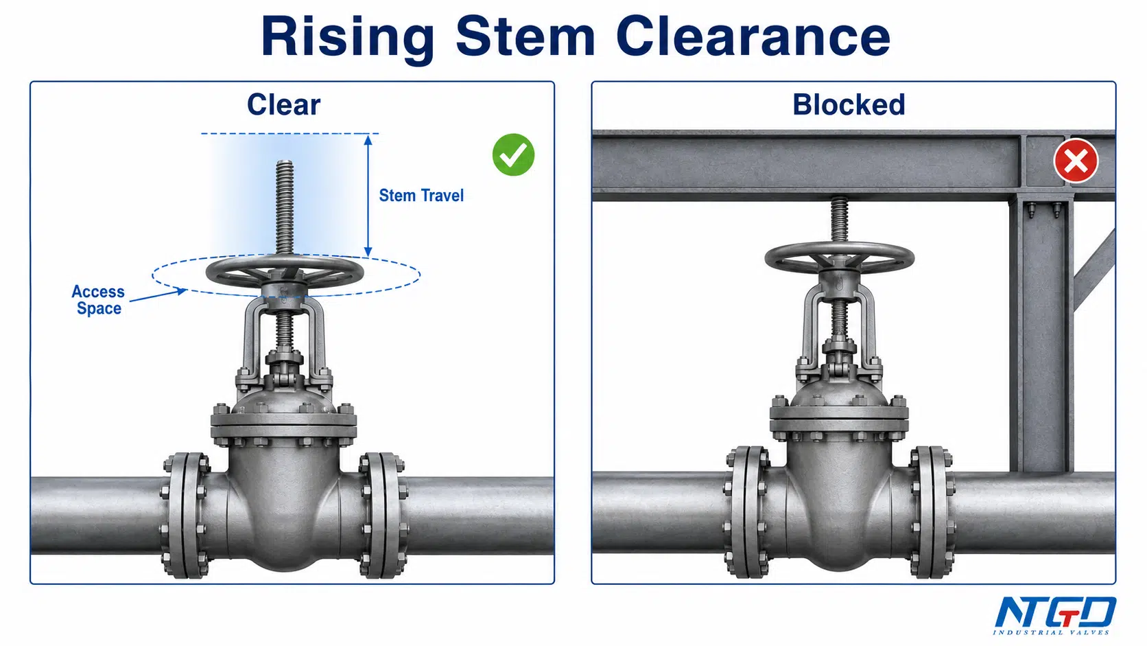
For selection-level clearance and position-visibility tradeoffs, compare Задвижка с восходящим штоком и задвижка без восходящего штока designs before fixing the installation position.
Non-rising stem designs may require less vertical clearance, but they still require handwheel access, packing access, and maintenance space. Gear-operated and actuated valves also require clearance for gearbox inspection, actuator wiring, limit switches, manual override, and removal.
If the project requires visible stem indication, an Задвижка OS&Y may provide clearer field position visibility, but clearance and maintenance access still need to be checked.
A correct gate valve installation position should consider both the current operation and future maintenance. A valve that is easy to install but impossible to service is not a good installation.
Направление потока, ориентация при монтаже и направление открытия — это не одно и то же
A common installation mistake is to mix up flow direction, installation orientation, and open direction. These three concepts are related to installation, but they do not mean the same thing.
Flow direction describes the direction media travels through the valve. Installation orientation describes how the valve is positioned in the pipeline, including stem direction and access. Open direction describes how the operator moves the handwheel, gearbox, or actuator to open or close the valve.
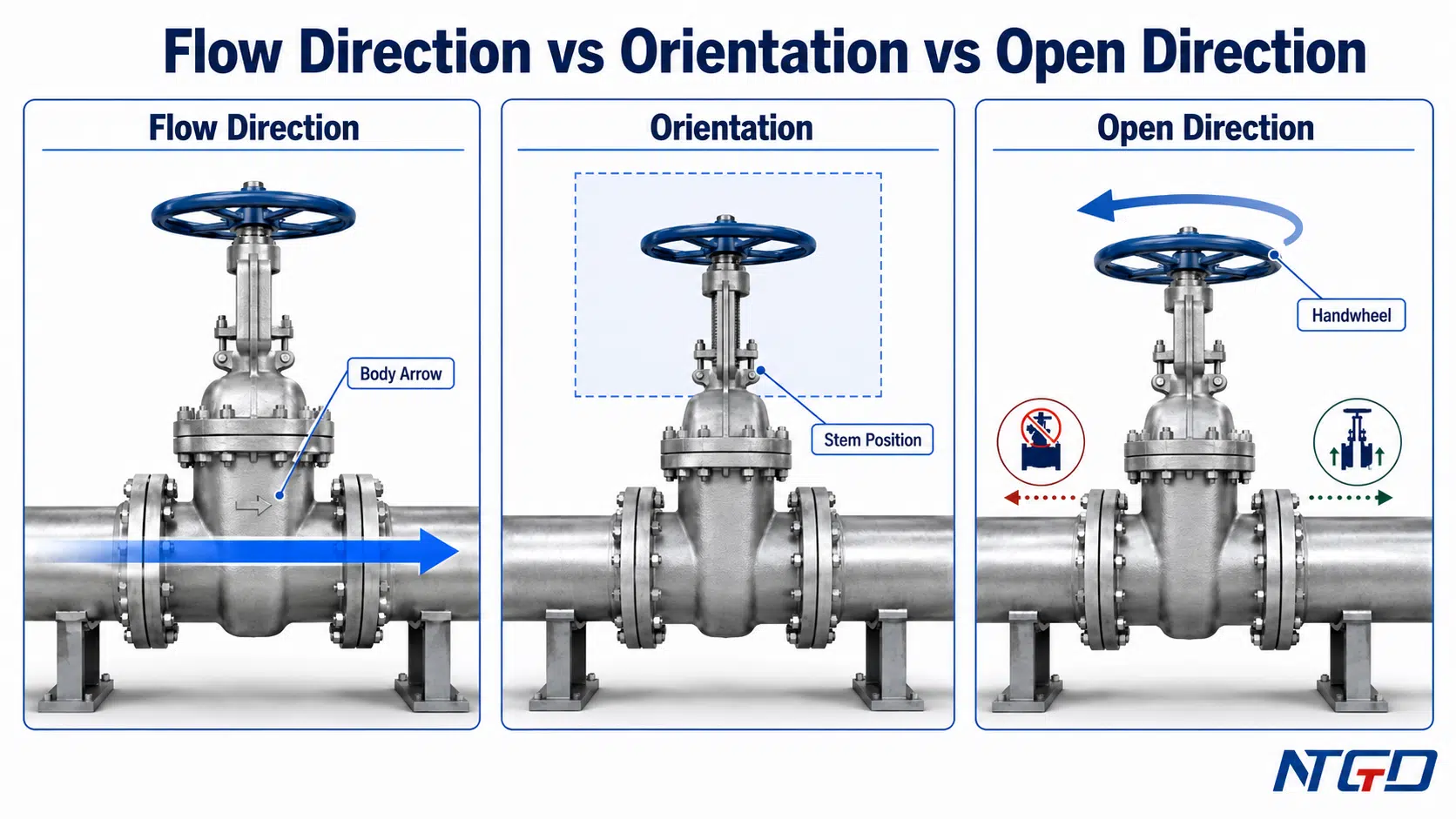
| Концепция | Что это значит | Where to Check | Common Installation Mistake |
|---|---|---|---|
| Направление потока | Direction of media through the valve bore | Body arrow, IOM, datasheet, project drawing | Ignoring a body arrow or special design note because “gate valves are usually bidirectional” |
| Ориентация при установке | Stem position, operator access, body support, pipe layout | IOM, project drawing, maintenance access review | Installing in the correct line but blocking stem travel, packing access, or actuator removal |
| Open direction | Direction of handwheel / gearbox / actuator operation | Operator marking, IOM, valve position indicator | Confusing handwheel rotation or actuator signal with pipeline flow direction |
| Положение установки | Physical placement of the valve in the system | Piping layout, support plan, access requirement | Installing where operation, inspection, lifting, or future maintenance is blocked |
Направление потока: обратите внимание на стрелку на корпусе, IOM и конструкцию клапана
Before installation, check the valve body markings, IOM, datasheet, and project drawing for any defined flow direction requirement. This is especially important when a body arrow, special accessory arrangement, bypass, drain, vent, pressure direction note, or project-specific installation detail is present.
If a body arrow is present, follow the manufacturer’s documentation and project requirements. If there is no body arrow, do not assume the direction is irrelevant without checking the IOM and valve design.
This article treats flow direction only as an installation checkpoint. A dedicated gate valve flow direction guide should explain the full flow-direction logic, seat performance considerations, and special service cases in more detail.
For a deeper review of bidirectional service, body arrows, and direction-related exceptions, use NTGD’s gate valve flow direction guide as the dedicated follow-up reference.
Рекомендации по установке: положение штока, доступ и опора
Installation orientation is mainly about how the valve is physically positioned. The most important checks are stem direction, handwheel or actuator access, pipe support, body support, drainage, and maintenance clearance.
A valve may be acceptable from a flow direction perspective but poor from an orientation perspective. For example, a valve may be installed in the correct flow direction but with blocked stem travel or poor access to the operator. That installation can still create operational and maintenance problems.
Направление открытия: управление маховиком и индикация положения
Open direction refers to how the valve is operated, not the direction of pipeline flow. Some valves use handwheel markings, position indicators, limit switches, or actuator signals to show open and closed positions.
During commissioning, the installer should confirm that the valve opens and closes smoothly and that the indicated position matches the actual operating condition. For rising stem and OS&Y gate valves, visible stem movement can help confirm position, but this should still be checked during operation.
Проверка опор труб, выравнивания фланцев и затяжки болтов
Pipe support and flange alignment are critical to gate valve installation. A valve is not a pipe support, pipe jack, or alignment tool. If the pipeline is misaligned, unsupported, or under stress, the valve body and end connections may experience loads that were not intended by the valve design.
Poor support and alignment can lead to flange leakage, body strain, high operating torque, packing leakage, seat distortion, or early maintenance problems.
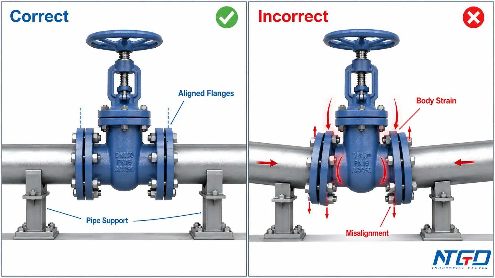
Избегайте нагрузки на трубы, перегрузки корпуса и несоосности
| Check | Почему это важно | Typical Problem | Корректирующие действия |
|---|---|---|---|
| Pipe centerline alignment | Keeps valve and pipe ends matched without forcing the body | Angular misalignment at flange, gasket leakage, or body strain | Adjust pipe support before final bolting |
| Flange parallelism | Allows even gasket compression across the sealing surface | One side of gasket over-compressed while the opposite side leaks | Re-align pipe and flange faces before tightening |
| Трубная опора | Prevents valve from carrying pipe weight or external line load | Body stress, flange leakage, or high operating torque | Add or adjust supports as specified |
| Valve support for large valves | Reduces external load on connected pipe and valve ends | Heavy valve hanging from flange or welded joint | Use support or hanger where required |
| Actuator / gearbox support | Prevents side load on stem, bonnet, or mounting interface | Heavy actuator pulling sideways and affecting operation | Follow manufacturer support requirements |
| Thermal movement allowance | Prevents stress during temperature change | Expansion load transferred into the valve body or end connection | Review expansion joints or support design |
The installer should never solve pipe misalignment by tightening bolts until the flanges pull together. This may create a sealed joint temporarily, but it can leave the valve body and gasket under stress.
Используйте подходящую прокладку и соблюдайте последовательность затяжки болтов
For flanged gate valves, sealing depends on the correct gasket, clean flange faces, proper alignment, and controlled bolting. The bolting sequence and final tightening method should follow the project specification or IOM.
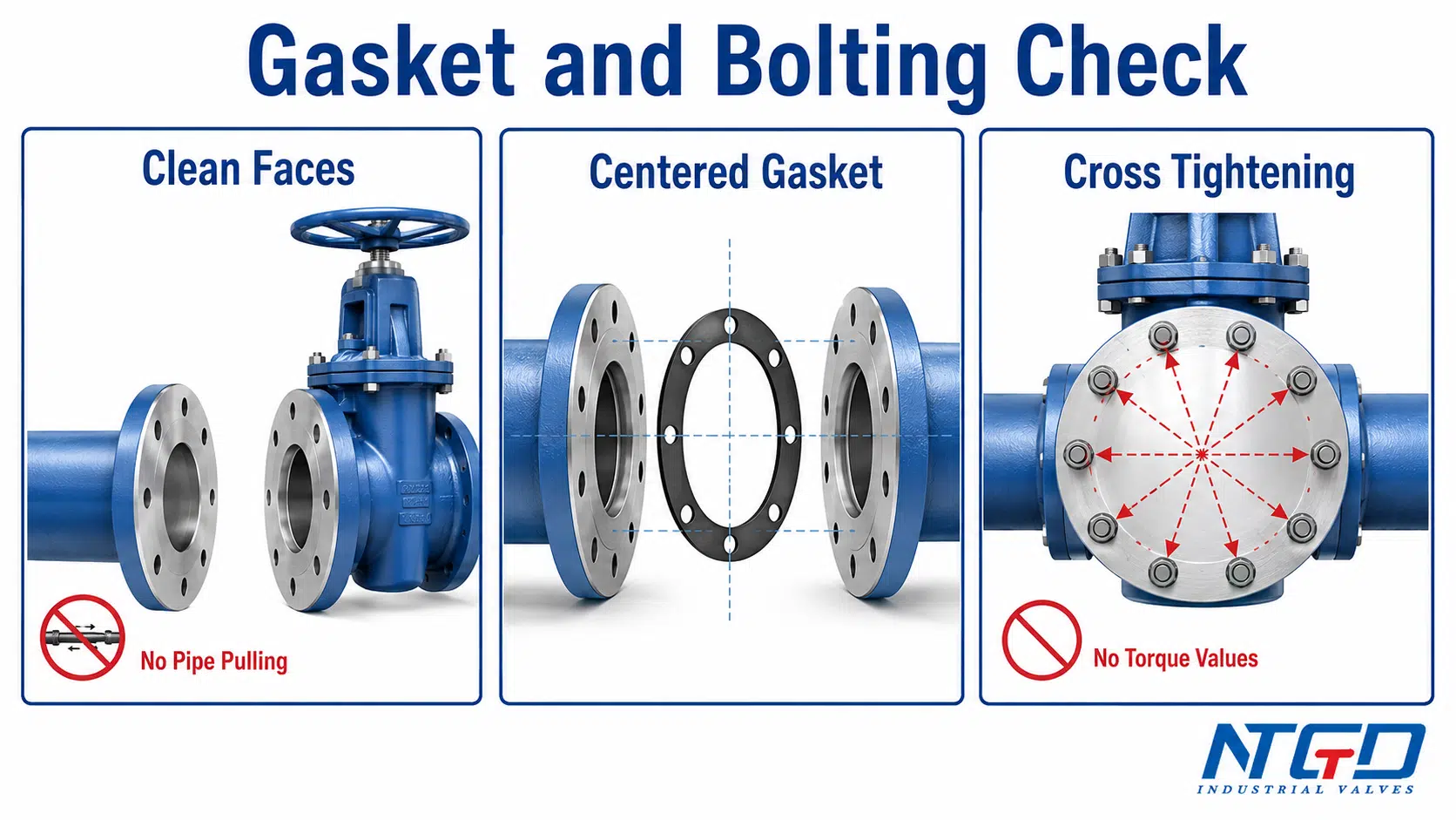
Avoid these practices:
- Reusing damaged gaskets.
- Mixing bolt materials or lengths.
- Tightening one side fully before the opposite side.
- Installing a gasket off-center.
- Tightening against dirty or damaged flange faces.
- Using bolt force to correct pipe misalignment.
- Applying unverified torque values.
The correct bolting process should provide even compression without damaging the gasket, flange faces, or valve body.
Примечания по подключению для монтажа с фланцевыми, сварными или механическими соединениями
Different end connections require different installation controls.
For flanged end gate valves, alignment, gasket seating, bolting, and flange face condition are the main checks.
For butt weld or socket weld gate valves, weld preparation, heat input, cleanliness, valve position, and protection of internal components should follow the approved welding procedure. Welding-specific details should not be improvised from a general installation guide.
For mechanical joint gate valves, especially in water pipeline or municipal applications, gasket arrangement, gland assembly, restraint, and buried access may be project-specific. These installations should be checked against the approved drawing and installation procedure.
Протоколы проверок, испытаний под давлением и ввода в эксплуатацию
After the gate valve is installed, the work is not complete until the valve has been checked for operation, leakage, pressure test requirements, and installation records. Commissioning helps confirm that the valve can be operated safely and that installation conditions have been documented before service.
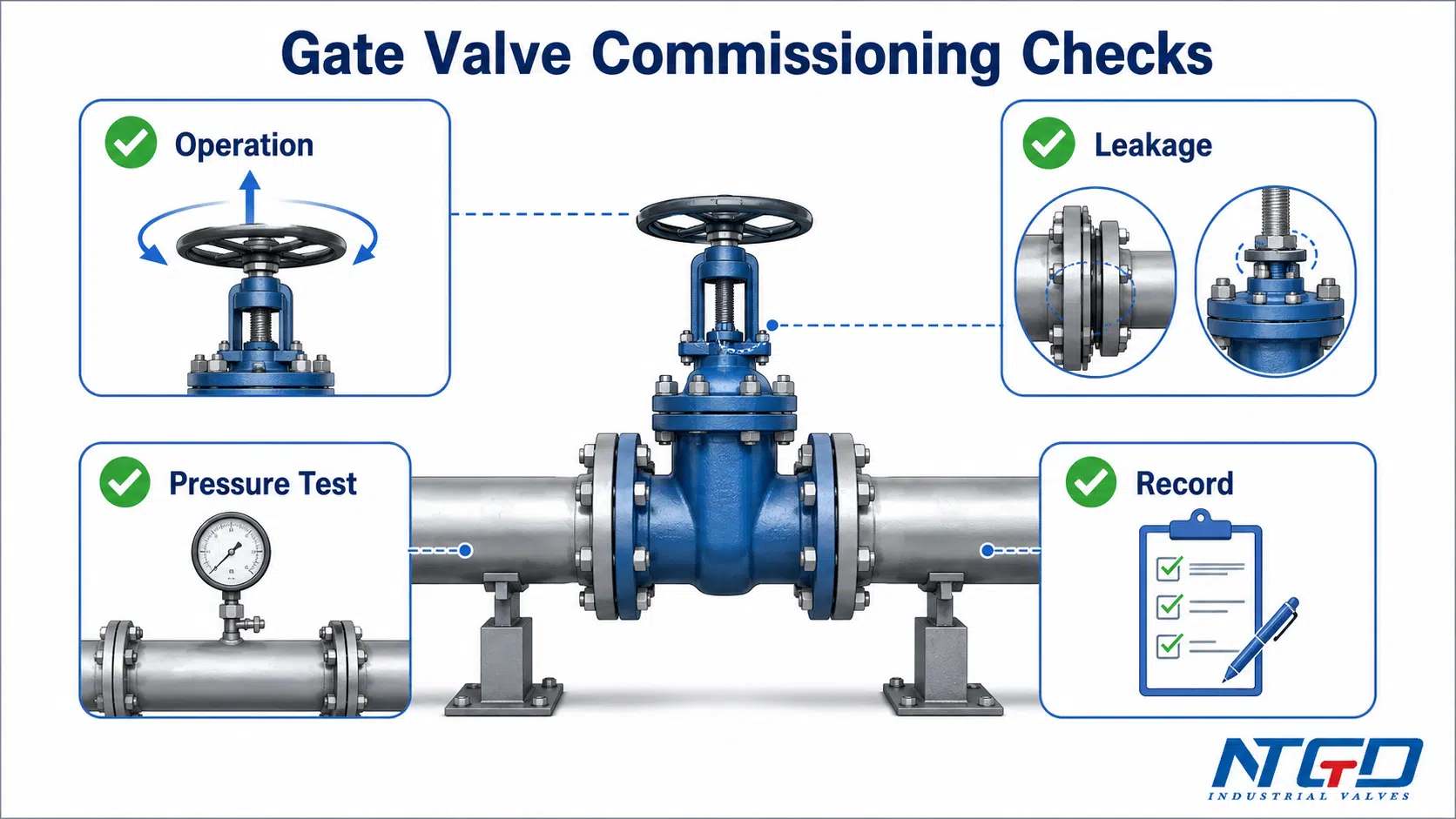
Проверка работы механизма открытия-закрытия перед запуском
The valve should be operated according to the IOM before startup or as part of commissioning. The purpose is to confirm smooth movement, correct operator function, adequate clearance, and visible position indication where applicable.
Before this check, operators should understand the gate valve opening and closing mechanism so that stem movement, gate travel, and position indication can be compared with the expected operating sequence.
During the operation check, verify:
- The handwheel, gearbox, or actuator is accessible.
- The stem moves correctly on rising stem or OS&Y designs.
- The valve does not bind or require abnormal torque.
- The open / close indication is understandable.
- The valve can reach the intended open and closed positions.
- No temporary protection blocks operation.
- The packing area, bonnet area, and end connections show no obvious issue.
If abnormal torque, noise, binding, leakage, or incomplete travel is observed, the condition should be investigated before service.
Обзор испытаний на герметичность и давление
Pressure and leakage tests should follow the project specification, applicable standards, and manufacturer documentation. This article does not provide universal test pressure values or acceptance criteria because those details depend on the valve class, material, design standard, seat type, service condition, and project requirement.
Before testing, confirm:
- The valve is installed in the correct line and position.
- The correct test procedure is approved.
- The valve position during testing is defined.
- The pipeline has been cleaned or flushed as required.
- Air, debris, and temporary materials are managed according to the test plan.
- The test result and leakage status are recorded.
Testing should not be used to compensate for poor installation. Applying test pressure to a poorly installed valve can worsen sealing damage or turn a correctable installation issue into a replacement-level problem.
If leakage appears during testing, the first review should include flange alignment, gasket condition, bolting control, pipe stress, debris control, and valve position before concluding that the valve body or seat design is the root cause.
Запишите ориентацию, результаты испытаний и условия монтажа
Commissioning records are useful for maintenance, warranty review, troubleshooting, and future shutdown planning. A basic record should identify the valve, installation location, orientation, operator access, test status, and any non-standard conditions.
| Commissioning Check | Record | Почему это важно |
|---|---|---|
| Valve tag and line number | Installed location and service | Confirms traceability |
| Ориентация | Stem direction and access condition | Helps future inspection and maintenance |
| Flow direction check | Body arrow / IOM / drawing confirmation | Prevents direction-related disputes |
| Operation check | Open-close result and abnormal torque if any | Confirms functional readiness |
| Pressure / leakage test | Test status and observed leakage | Supports commissioning documentation |
| Поддержка и согласование | Visible pipe support / flange alignment notes | Helps diagnose future leakage |
| Аксессуары | Gearbox, actuator, limit switch, bypass, drain, vent | Confirms complete installation |
| Non-standard conditions | Space limitation, unusual orientation, special support | Supports future maintenance planning |
Распространенные ошибки при монтаже задвижек
Gate valve installation problems often appear during pressure testing, startup, or early operation. Many of these problems are preventable if the installer follows a controlled checklist and does not treat the valve as a simple pipe fitting.
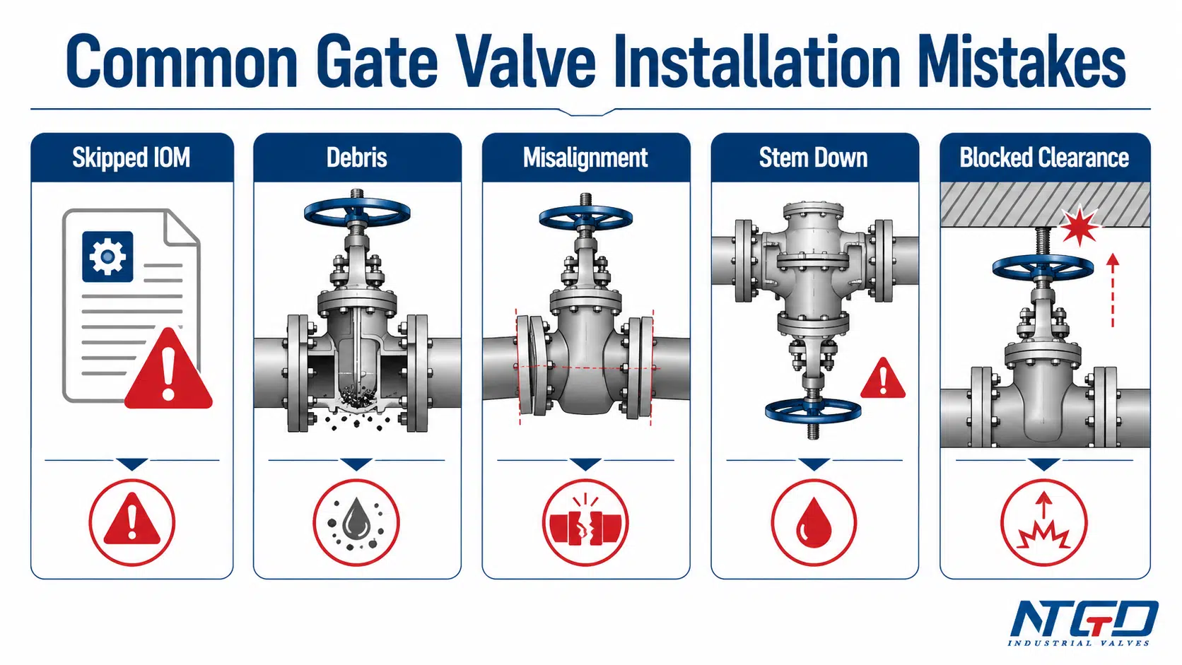
| Ошибка | Возможные последствия | Правильная проверка |
|---|---|---|
| Installing without reviewing the IOM | Wrong orientation, missed special instruction, damaged component | Review the IOM, datasheet, project drawing, and valve markings before installation |
| Using the valve to pull misaligned pipe together | Body strain, flange leakage, high torque | Align and support the pipe before bolting; do not use flange bolts as alignment tools |
| Leaving debris in the pipeline | Seat damage, leakage, incomplete closure | Clean and flush the line as required before final operation and testing |
| Installing stem-down without approval | Poor drainage, access difficulty, debris accumulation, maintenance risk | Avoid stem-down installation unless the IOM and project requirements specifically allow it |
| Blocking rising stem travel | Valve cannot fully open, position indication becomes unreliable | Reserve full stem movement clearance before final positioning |
| Incorrect gasket or bolting | Flange leakage or gasket failure | Use specified gasket, clean flange faces, correct centering, and controlled tightening |
| Ignoring actuator or gearbox weight | Side load, stem stress, operation problems | Review actuator support, access, and removal space before installation |
| Confusing flow direction with stem orientation | Correct flow but poor access, or incorrect direction where direction is defined | Check flow direction, installation orientation, and open direction separately |
| Treating knife gate installation as the same as ordinary gate valve installation | Wrong seat-side, pressure direction, or slurry-service decision | Review knife gate valve requirements separately |
| Skipping commissioning records | Difficult troubleshooting and unclear responsibility | Record operation, test result, orientation, support condition, and non-standard conditions |
Ошибки, приводящие к утечке, высокому крутящему моменту или повреждению седла
Debris left in the line can move into the seating area, scratch sealing surfaces, create internal leakage, and cause a pressure test problem before the system is even placed into service. Pipe misalignment follows a similar failure path: the installer may force the joint closed, but body strain and uneven gasket compression can later appear as flange leakage, high torque, or repeated maintenance.
Leakage during testing should therefore be reviewed as an installation system problem, not only as a valve quality problem. The valve, gasket, flange faces, bolting, pipe alignment, debris control, and test setup all need to be checked together.
If leakage, abnormal torque, corrosion, or hard operation appears after commissioning, route the issue to NTGD’s Обслуживание и устранение неисправностей задвижек guide instead of expanding this installation article into a maintenance manual.
Ошибки, приводящие к проблемам с доступом для технического обслуживания
A valve installed in a cramped or blocked location may pass pressure testing but still fail as a maintainable installation. Poor access can prevent packing adjustment, actuator service, stem inspection, or safe operation during shutdown.
For rising stem and OS&Y designs, lack of clearance is not only an access problem. It can prevent full opening, make position indication unreliable, and create interference with platforms, insulation, pipe racks, or equipment.
Ошибки, связанные с путаницей в типах клапанов
Ordinary wedge gate valves, knife gate valves, resilient seated gate valves, pressure seal gate valves, and actuated gate valves may have different installation details. A general gate valve installation guide should not be used to override the IOM for a special valve design.
Knife gate valves are especially important to separate from ordinary gate valves because their installation may involve seat side, slurry direction, unidirectional or bidirectional design, and specific orientation rules.
Поддержка по вопросам применения и технических характеристик до направления запроса предложений
Standard gate valve installation guidance is useful, but it may not be enough for every project. If the service condition, line orientation, actuator arrangement, support condition, end connection, or testing requirement is unusual, the installation should be reviewed before the valve is ordered or installed.
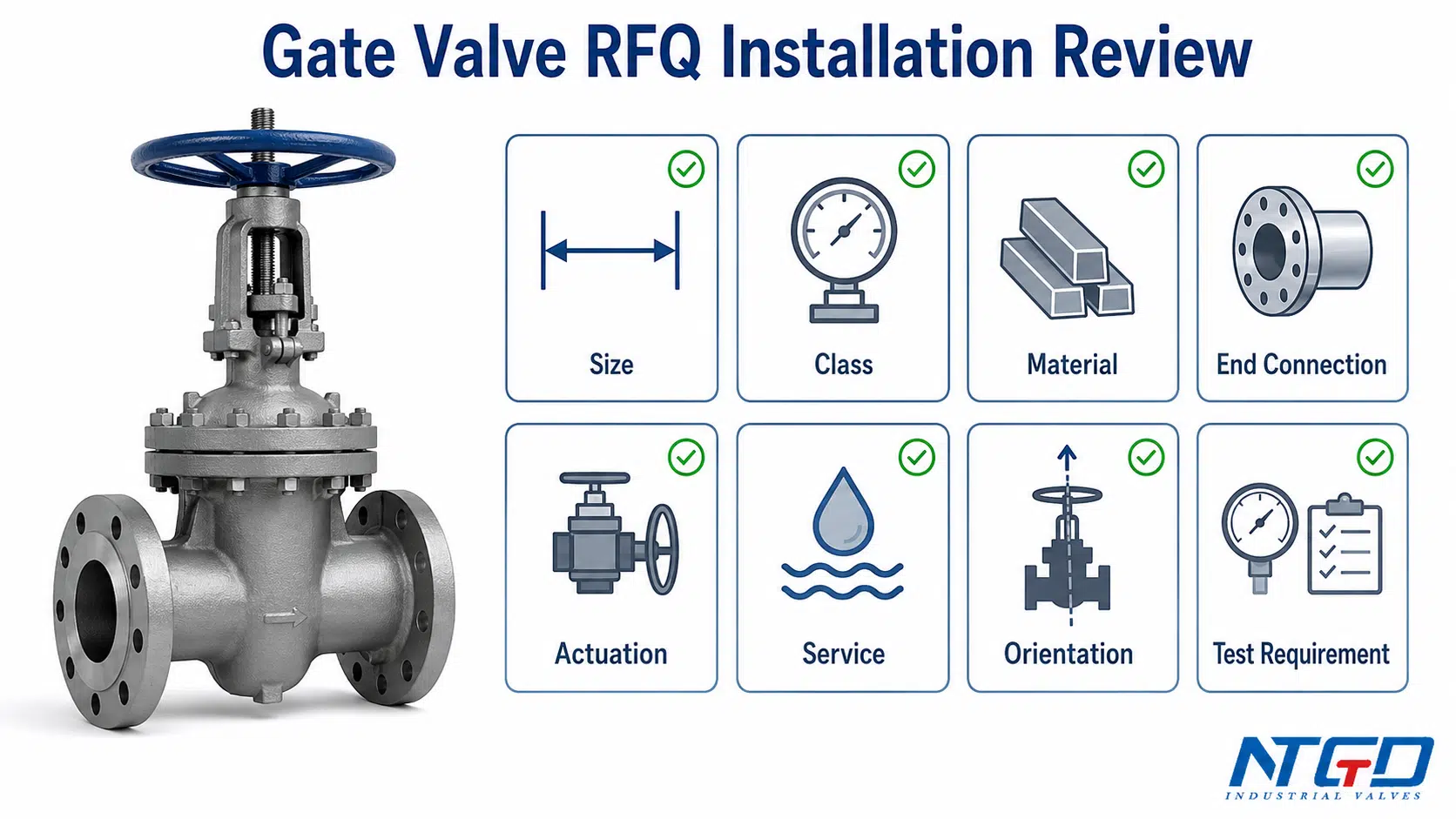
Когда стандартных инструкций по установке недостаточно
Additional review is recommended when the project includes:
- High-pressure or high-temperature service.
- Steam, thermal cycling, or severe service.
- Corrosive or abrasive media.
- Buried or underground installation.
- Large-diameter gate valves.
- Heavy gearboxes or actuators.
- Limited stem clearance.
- Horizontal stem or unusual orientation.
- Welded end connections.
- Mechanical joint or municipal waterworks requirements.
- Special pressure test or leakage test requirements.
- Limited maintenance access after installation.
When any of these conditions are present, a pre-RFQ engineering review with the manufacturer can help avoid costly on-site modifications, installation rework, or delayed commissioning.
In these cases, the valve selection, installation position, support arrangement, and commissioning procedure should be confirmed before shipment or site installation.
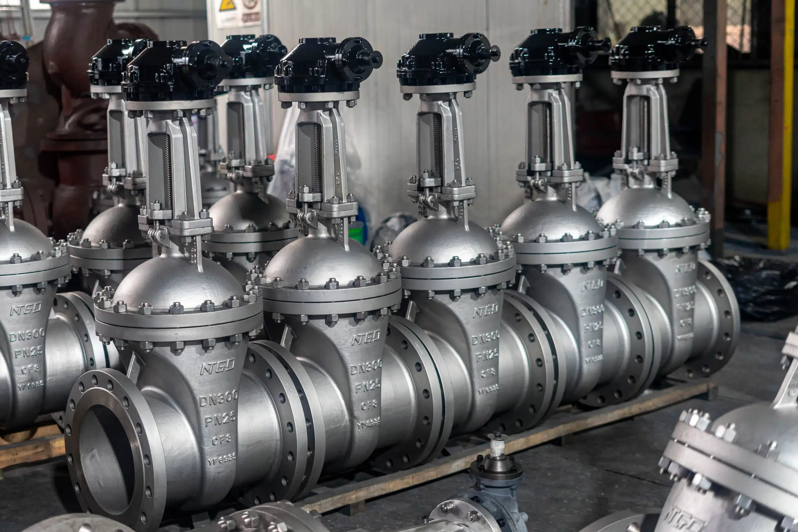
Информация, которую необходимо уточнить у производителя клапана
| Информация | Why It Helps Installation Review |
|---|---|
| Размер клапана и класс давления | Confirms body, end connection, support, and lifting considerations |
| Материал корпуса и отделки | Confirms service suitability and handling requirements |
| Концевое соединение | Defines flange, weld, or mechanical joint installation controls |
| Pipeline orientation | Helps review stem position and access |
| Preferred stem orientation | Confirms whether horizontal or unusual orientation is acceptable |
| Тип привода | Determines clearance, support, wiring, and maintenance access |
| Обслуживание среднее | Helps identify debris, corrosion, temperature, or sealing concerns |
| Рабочее давление и температура | Supports installation and testing review |
| Test requirements | Confirms pressure / leakage test expectations |
| Project drawing or valve tag | Helps check exact installation position and special notes |
Как NTGD может помочь в подборе задвижек и проверке их монтажа
For industrial gate valve projects, NTGD can review valve specification requirements together with service conditions, line layout, end connection, installation orientation, pipe support and alignment concerns, actuator clearance, and commissioning or test requirements. This type of review is most useful before the valve is ordered, shipped, or installed on site.
A clear RFQ should include size, pressure class, material, end connection, service medium, operating pressure and temperature, pipeline orientation, actuator requirement, testing requirement, and any space limitation around the stem or operator.
Часто задаваемые вопросы об установке задвижек
Можно ли установить задвижку в горизонтальном положении?
Да, задвижку зачастую можно устанавливать в горизонтальном трубопроводе, однако такая установка допустима только после проверки положения штока, веса привода, доступа оператора, опоры трубы и требований руководства по эксплуатации. При наличии возможности обычно предпочтительна установка с вертикальным штоком, тогда как горизонтальное расположение штока или другие варианты ориентации следует согласовывать с конструкцией клапана и требованиями проекта.
Можно ли устанавливать задвижки в перевернутом положении?
For most industrial gate valves, upside-down or stem-down installation is generally not recommended unless the manufacturer’s IOM and project specification clearly allow it. The risk is not only poor operation. This position can create debris accumulation, drainage problems, limited packing inspection, difficult maintenance, and long-term access issues.
Должен ли шток задвижки быть направлен вверх?
Stem-up orientation is often preferred because it helps operation access, visible stem travel, position indication for rising stem or OS&Y valves, packing inspection, and maintenance. However, the final orientation should always be checked against the IOM, project drawing, actuator arrangement, and site access conditions.
Имеет ли значение, в каком направлении устанавливается задвижка?
Yes, but “which way” can mean different things. Flow direction, installation orientation, and open direction are separate checks. The installer should check body markings and IOM for flow direction, confirm stem position and support for orientation, and verify handwheel or actuator movement during commissioning.
Есть ли у задвижки направление потока?
Многие стандартные задвижки используются в качестве отсечных клапанов в обоих направлениях, однако в некоторых конструкциях, в соответствии с прилагаемым оборудованием или проектными требованиями может быть определено предпочтительное или обязательное направление потока. Перед монтажом всегда необходимо проверять стрелку на корпусе, руководство по эксплуатации, технические характеристики и проектный чертеж.
Должен ли задвижка быть открыта или закрыта во время монтажа?
Требуемое положение клапана зависит от этапа монтажа и типа концевого соединения. При фланцевом соединении, сварке, промывке, испытании под давлением и вводе в эксплуатацию могут потребоваться различные положения клапана или методы его защиты. Окончательные требования должны определяться руководством по эксплуатации и техническому обслуживанию (IOM) и проектной документацией, а не универсальными правилами.
Установка ножевого задвижки аналогична установке обычной задвижки?
Нет. Для ножевых задвижек могут действовать иные правила монтажа, поскольку их конструкция седла, условия эксплуатации с шламовыми средами, направление давления, а также требования к одно- или двунаправленному прохождению могут отличаться от обычных задвижек. Монтаж ножевых задвижек следует изучать в отдельном руководстве по ножевым задвижкам или в руководстве по эксплуатации и техническому обслуживанию (IOM) производителя.
Заключение
Gate valve installation should be treated as an engineering checklist, not a simple fitting task. The key checks include reviewing the IOM and project drawing, confirming valve specification, inspecting the valve and pipeline, removing debris, checking installation orientation, supporting the pipe, aligning flanges or end connections, controlling gasket and bolting work, verifying flow direction requirements, and completing operation and commissioning records.
The most common installation risks come from skipped document review, pipe misalignment, debris, poor orientation, blocked stem travel, incorrect gasket or bolting work, and confusion between flow direction, installation orientation, and open direction.
For industrial projects, a gate valve installation procedure should close with a checklist-based review before service. When service condition, orientation, actuator arrangement, pipe support, end connection, or testing requirement is unclear, confirm the installation plan with the valve manufacturer before site work begins.
