Author Name: Bruce Zheng
Author Role: Co-Founder and Valve Engineer at NTGD Valve
Author Bio: Bruce Zheng is Co-Founder and Valve Engineer at NTGD Valve, focusing on industrial valve selection, application, and technical content for global B2B buyers.
Last Updated: June 16, 2026
Quick Answer: Do Butterfly Valves Have a Flow Direction?
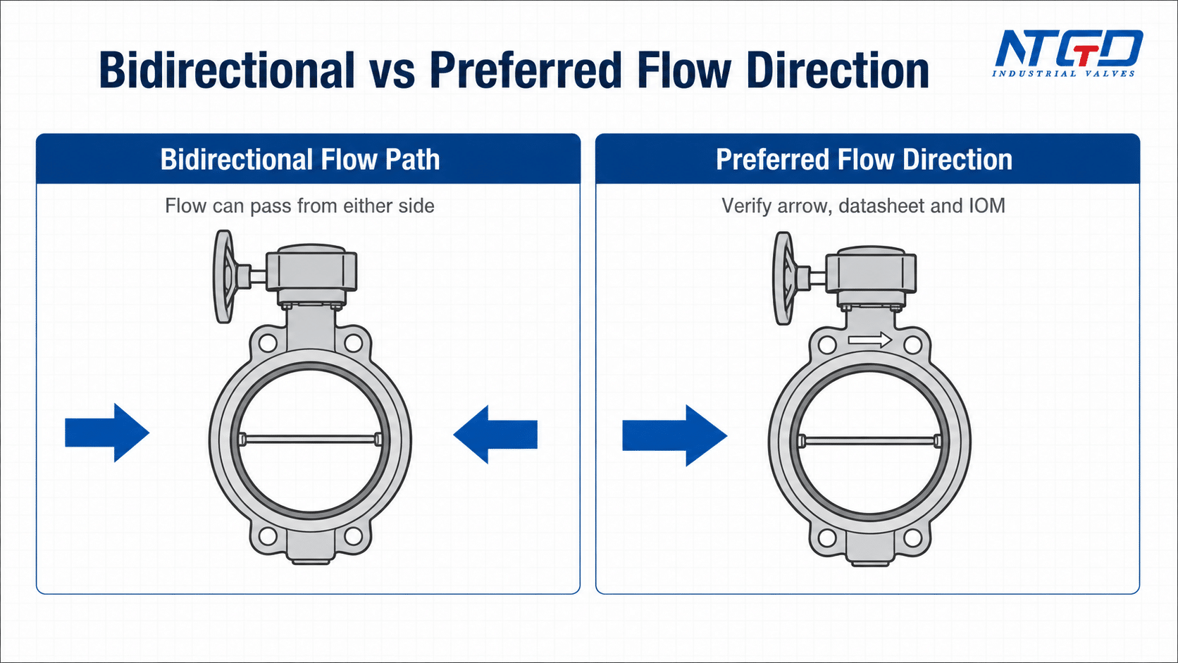
Many standard butterfly valves can allow flow in either direction, especially common concentric or resilient-seated designs used in general industrial service. However, this does not mean every butterfly valve can be installed without checking direction.
The correct butterfly valve flow direction depends on the valve design, seat arrangement, disc geometry, pressure side, body arrow, nameplate marking, project drawing, datasheet and installation manual. Some valves are effectively bidirectional in common service. Others may have a preferred flow direction because of seat loading, offset design, sealing performance, torque behavior or manufacturer-specific construction.
For field installation and RFQ review, the safest engineering answer is:
A butterfly valve may be bidirectional, but the installation direction should still be verified against the valve design, flow arrow, datasheet, drawing and IOM before installation.
Engineering Bottom Line: Standard concentric and resilient-seated butterfly valves in common clean service often allow bidirectional flow. Direction sensitivity increases with double-offset, triple-offset, metal-seated, actuated or critical shutoff designs. The final check should always be the datasheet, IOM, body arrow and project drawing, not a general assumption.
The short engineering answer
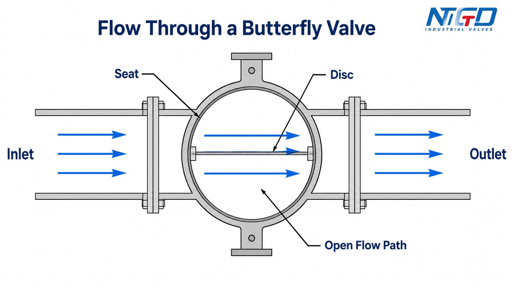
A butterfly valve controls flow with a rotating disc. When the valve opens, the disc turns away from the sealing position and allows fluid to pass around the disc. Because the valve body is compact and the flow path usually passes through the centerline of the valve, many users assume the valve has no directional requirement.
That assumption is only partly correct.
For many standard resilient-seated butterfly valves, flow can often pass from either side. For high-performance, double-offset, triple-offset or metal-seated designs, the preferred pressure side and sealing direction may be more important. In those cases, installing the valve against the preferred direction can affect shutoff performance, seat wear, operating torque or actuator sizing.
A practical boundary is this: if the valve is a basic resilient-seated design in non-critical service, bidirectional installation is often acceptable after documentation review. If the valve uses offset geometry, metal sealing, large actuation, critical shutoff or reverse pressure service, the preferred flow direction must be verified before installation. Treating a preferred direction as optional can lead to leakage, higher torque, shorter seat life or site rework.
When bidirectional flow is usually acceptable
Bidirectional flow is usually more likely when the valve is a standard concentric butterfly valve, the seat design is symmetrical, the service is moderate, and the manufacturer’s documentation does not specify a required direction. These valves are often used in water, HVAC, general utility, low-to-medium pressure industrial pipelines and similar services.
Even in these cases, the installer should still check:
- the body arrow or cast marking, if present;
- the project flow direction on the drawing;
- the tag number and datasheet;
- the valve seat design;
- the IOM or installation instruction;
- whether the valve is intended for isolation, regulation or special service.
Bidirectional capability is a valve design feature. It is not a replacement for installation verification.
When preferred flow direction must be checked
Preferred flow direction becomes more important when the butterfly valve uses an offset shaft, metal seat, laminated seal, pressure-assisted sealing arrangement, special seat retaining structure or large actuator. It should also be checked when the service involves higher pressure, high temperature, steam, gas, abrasive media, slurry, solids, vacuum, corrosive media or critical shutoff.
If the valve has a body arrow, tag instruction, seat-side marking or manufacturer direction note, the installation should not be decided by habit. The marking and documents should be reviewed together. If the documents do not agree, the project team should clarify the direction before the valve is installed.
What Does Butterfly Valve Flow Direction Mean?
Butterfly valve flow direction describes the intended direction of fluid movement through the valve body. In simple terms, it answers this question:
Which side should be upstream, and which side should be downstream when the valve is installed in the pipeline?
This is related to installation direction and valve orientation, but the three terms solve different engineering questions.
Flow direction vs installation direction
Flow direction refers to the movement of the process fluid. Installation direction refers to how the valve body is physically installed relative to that flow.
For example, a pipeline may carry water from left to right on a drawing. The valve may then need to be installed so that its arrow, pressure side or preferred seat side matches that process flow. In another project, the same valve type may be installed in a vertical line, but the flow direction could be upward or downward.
A correct butterfly valve installation direction should match both the project flow direction and the valve manufacturer’s direction requirement.
| Term | What it means | Why it matters |
|---|---|---|
| Flow direction | Direction of media movement through the pipeline | Defines upstream and downstream sides |
| Installation direction | Physical installation of the valve body so the correct upstream / downstream side matches the pipeline flow | Prevents wrong seat loading, pressure-side mismatch or incorrect arrow direction |
| Preferred flow direction | Manufacturer-recommended upstream side or pressure side for best shutoff, torque behavior, seat life or documented installation requirement | Important for offset, high-performance, metal-seated or critical shutoff designs |
| Body arrow | Marking on the valve body or tag | May indicate flow direction, pressure direction or installation reference |
| IOM / datasheet direction | Manufacturer or project document instruction | Should be used with project drawings for final direction confirmation |
Flow direction vs valve orientation
Valve orientation describes the physical position of the valve in the pipeline. It may refer to a horizontal pipe, vertical pipe, shaft position, stem position, actuator clearance or gearbox position.
A horizontal butterfly valve installation and a vertical butterfly valve installation may both be acceptable for a given design, but acceptability depends on valve size, media condition, seat design, actuator weight, shaft loading and manufacturer guidance.
Flow direction and orientation should not be collapsed into one rule. A valve may allow flow from either side but still require a certain shaft orientation for dirty media, large size, actuator support or maintenance access.
Why disc, seat and pressure side matter
The butterfly valve disc rotates inside the valve body and seals against a seat or sealing surface. The way pressure pushes the disc toward or away from the seat can influence sealing behavior.
In a basic resilient-seated concentric butterfly valve, the disc and seat are often arranged in a relatively symmetrical way. In offset or metal-seated designs, the sealing geometry is more complex. The pressure side, seat side and non-seat side may affect how the disc loads the seat during shutoff.
A butterfly valve can therefore be described as bidirectional in one context, but still have a preferred flow direction in another context. The correct interpretation depends on what “bidirectional” means in the datasheet: open flow path, shutoff capability, pressure direction or installation position.
Are Butterfly Valves Bidirectional or Directional?
Butterfly valves can be bidirectional or directional depending on design. The issue is not only whether fluid can physically pass through the valve from either side. In most open butterfly valves, fluid can pass through the body in either direction. The real issue is whether the valve can seal, operate and maintain acceptable performance in both directions under the project conditions.
Standard concentric and resilient-seated butterfly valves
Standard concentric butterfly valves usually have the stem located at the centerline of the disc, and the disc rotates against a resilient seat. Many of these valves are commonly used in services where bidirectional sealing is expected.
The installer should still check the datasheet and body marking. Some designs may include a seat side, preferred pressure side, flow arrow or manufacturer instruction. The valve may also be affected by size, line velocity, media, pressure class and actuator selection.
Double-offset and high-performance butterfly valves
Double-offset and high-performance butterfly valves are often used where better sealing performance, lower seat wear or higher operating conditions are required compared with basic resilient-seated valves. Their disc and shaft geometry can make flow direction and pressure side more relevant.
These valves should not be treated as generic direction-free valves. The preferred flow direction may affect sealing load, torque and seat life. If the valve is used for shutoff service, the project team should confirm whether the valve is suitable for the required shutoff direction under the specified pressure and temperature.
Triple-offset and metal-seated butterfly valves
Triple-offset and metal-seated butterfly valves are more direction-sensitive in many applications because their sealing geometry is designed around precise contact between the disc seal and body seat. Some designs may support bidirectional sealing, but the preferred flow direction can still be specified for best performance.
For this reason, triple offset flow direction should normally be handled through the product datasheet, drawing, IOM and product-specific triple-offset specification, not through a general assumption.
Bidirectional sealing does not always mean direction-free installation
Bidirectional flow path, bidirectional sealing and preferred pressure side are different levels of information. They should not be used interchangeably during valve selection or installation.
The following table separates bidirectional ability from preferred installation direction.
| Valve condition | What it usually means | What to check | Risk if ignored |
|---|---|---|---|
| Bidirectional flow path | Fluid can physically pass through the open valve from either side | Whether sealing is also bidirectional under the required service conditions | Assuming open-flow capability equals shutoff capability |
| Bidirectional sealing | Valve may seal from either side under specified conditions | Pressure / temperature rating, shutoff direction, datasheet rating statement and test direction if specified | Overstating performance outside the documented design conditions |
| Preferred flow direction | Manufacturer recommends one direction for best operation | Body arrow, pressure side, seat side, datasheet and IOM note | Reduced sealing reliability, higher torque, seat wear or reduced shutoff performance |
| Directional design | Valve must be installed in a specified direction | Project drawing, tag, body marking and IOM installation section | Wrong installation, field rework and possible leakage |
| Orientation-sensitive installation | Valve position matters due to shaft, actuator, solids, drainage or layout | IOM, media condition, actuator support and project layout | Poor operation, sediment build-up or actuator loading issues |
If the project requires tight shutoff, pressure reversal, critical isolation or documented sealing performance, confirm the sealing direction from the datasheet and IOM. Do not rely only on the fact that the valve can pass flow when open.
Butterfly Valve Preferred Flow Direction by Design Type
The phrase butterfly valve preferred flow direction should be used carefully. It does not mean every butterfly valve has a fixed one-way flow requirement. It means the manufacturer or project specification may identify a direction that gives better sealing, torque behavior, seat protection or service reliability.
An industry overview of butterfly valve design types separates resilient-seated, lined, high-performance / double-offset and triple-offset designs, which supports treating valve design as a key direction-check variable.
Design-type direction matrix
| Butterfly valve design | Typical direction behavior | Direction sensitivity | What to verify before installation | IOM / Datasheet note |
|---|---|---|---|---|
| Concentric resilient-seated butterfly valve | Often suitable for bidirectional flow in general service | Low to medium | Seat design, body marking, datasheet and project flow direction | Usually lower sensitivity, but still check datasheet and body marking |
| Wafer / lug resilient-seated butterfly valve | Often installed in common utility and water services | Low to medium | Whether the valve is suitable for the required bidirectional shutoff | Connection type does not decide flow direction; internal design does |
| Flanged butterfly valve | Direction behavior depends on internal design, not only flange type | Medium | Datasheet, seat construction, body arrow and drawing | Flanges define end connection, not the sealing direction |
| Double-offset butterfly valve | May have preferred pressure side or sealing direction | Medium to high | Manufacturer direction note, pressure side and torque data | Confirm preferred pressure side and torque basis |
| High-performance butterfly valve | Often more design-specific than basic resilient-seated valves | Medium to high | IOM, seat material, service condition and actuator sizing | Verify direction, pressure side and actuator sizing assumptions |
| Triple-offset butterfly valve | May have a specified or preferred direction depending on seal design | High | Product datasheet, IOM, project specification and manufacturer confirmation | Confirm seal design, preferred pressure side and product-specific installation note |
| Metal-seated butterfly valve | Direction behavior may depend on sealing geometry and pressure side | High | Seat side, sealing direction, shutoff requirement and pressure / temperature limits | Confirm seat side, sealing direction and service limits before installation |
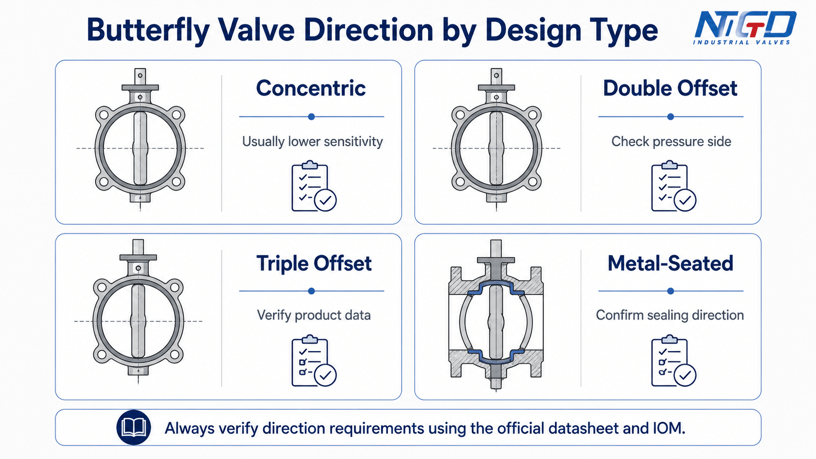
The table should be used as a direction-check framework, not as a universal rule. The exact flow direction requirement depends on the manufacturer’s design and the project specification.
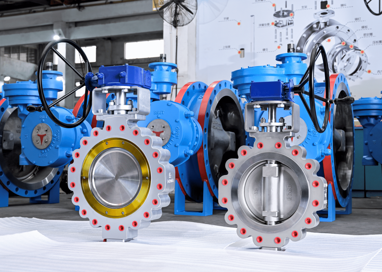
The following NTGD butterfly valve product video can be used as a visual reference for direction-sensitive offset and triple-offset butterfly valve designs. Final flow direction should still be confirmed from the product datasheet, drawing and IOM.
Seat side, non-seat side and pressure-assisted sealing
Some butterfly valve designs refer to a seat side and a non-seat side. In simple terms, the seat side is the side where the sealing interface is most directly supported or loaded by the design. The non-seat side is the opposite side.
In some designs, upstream pressure helps press the disc or seal into the seat. In others, pressure from the opposite side may change the sealing force, torque or wear pattern. This is why a valve may have a preferred pressure side even if it can physically pass flow from either direction.
For buyers and engineers, the practical point is simple:
Do not decide seat side or non-seat side by looking only at the outside shape of the valve. Check the datasheet, drawing, body marking and IOM.
Seat side and non-seat side can affect pressure-assisted sealing behavior and preferred installation direction. For field installation, the correct side should be confirmed from project documents and supplier clarification, not from external appearance alone.
When to confirm direction with the manufacturer
Manufacturer confirmation is recommended when:
- the valve is double-offset, triple-offset, eccentric or high-performance;
- the valve is metal-seated;
- the service is high temperature, steam, gas, slurry or abrasive media;
- shutoff performance is critical;
- the valve has a body arrow or seat-side marking;
- the actuator size seems close to the required torque;
- the valve will be installed in a vertical line;
- the project drawing and valve marking appear inconsistent;
- the valve is large, heavy or difficult to remove after installation.
In RFQ communication, direction confirmation should be made before production or shipment, not after the valve arrives at site.
How to Read the Body Arrow, Nameplate and Datasheet
A butterfly valve flow direction arrow can help installers identify the intended direction, but the arrow should be interpreted correctly. Depending on the design, a marking may indicate flow direction, pressure direction, preferred sealing direction, seat side or a project-specific installation reference.
The safest approach is to read the arrow together with the nameplate, drawing, datasheet and IOM.
If the body arrow, nameplate, project drawing, datasheet and IOM appear inconsistent, do not guess at site. Cross-check the manufacturer IOM, approved datasheet and project drawing / P&ID together. If the direction is still unclear, request written clarification before installation and keep the clarification with the project records.
What a flow arrow may indicate
A body arrow may show the direction in which the manufacturer expects the valve to be installed. On some valves, the arrow is directly related to media flow. On others, it may be tied to pressure side or sealing direction.
If the valve is used in a critical service, the arrow should not be treated as a decorative casting mark. It should be checked against the tag and project documentation.
| Marking or document | What it may indicate | How to verify | Installation action |
|---|---|---|---|
| Cast body arrow | Flow direction, preferred direction or pressure side | Compare with datasheet, IOM and project flow direction | Cross-check arrow meaning with datasheet / IOM before installation |
| Nameplate / tag | Valve size, class, material, trim or tag information | Match with project line list and datasheet | Confirm the valve belongs to the correct line and service |
| Drawing arrow | Project flow direction or installation reference | Compare with P&ID, layout and valve marking | Align valve marking with project P&ID / layout flow direction |
| Datasheet | Valve design, seat, pressure class, service and direction note | Review flow direction, installation or pressure side notes | Use as a key engineering reference before installation |
| IOM | Manufacturer installation and orientation instruction | Check for direction, orientation and service limits | Follow direction / orientation limits before field installation |
| Supplier confirmation | Clarifies uncertain or project-specific direction | Request before shipment or installation | Record direction clarification in project documentation |
Flow direction vs pressure-bearing direction
Flow direction and pressure-bearing direction can be related, but they are not always the same concept.
Flow direction describes where the process media moves during operation. Pressure-bearing direction describes which side applies pressure to the closure and sealing system. In many pipelines, they are the same in normal operation. In some systems, pressure may reverse during shutdown, pump stop, backflow, testing or isolation.
This is important for butterfly valves used in shutoff service. A valve may open and pass flow from either side, but its shutoff rating, leakage behavior or torque may be different depending on pressure direction.
In systems where pump stop, reverse pressure, hydrotest, isolation or backflow can occur, normal flow direction and shutoff pressure direction may not be the same question. In those cases, the datasheet and IOM should be checked for sealing direction, pressure side or direction-specific limits.
What to check in drawings, tags, datasheets and IOM documents
Before installation, the installer or project engineer should confirm the following items:
- Does the valve body have a flow arrow?
- Does the datasheet mention preferred flow direction?
- Does the IOM specify an upstream side or seat side?
- Does the project drawing show flow direction?
- Does the tag number match the line and service?
- Does the valve type match the specification?
- Does the actuator orientation create clearance or load concerns?
- Does the service allow pressure reversal?
- Is the valve required to seal in one direction or both directions?
- Has the supplier confirmed direction for offset or metal-seated designs?
A direction mismatch found during document review is easier to correct than a direction mismatch discovered after installation.
Butterfly Valve Installation Direction and Orientation
Butterfly valve installation direction should be confirmed by matching the project flow direction with the valve’s design requirements. This is different from writing a complete installation procedure. Full installation details such as flange alignment, bolt tightening, gasket selection, actuator wiring and travel stop setting should be handled by the project specification and the manufacturer’s IOM.
This section focuses only on direction and orientation checks.
Horizontal and vertical pipeline installation
Butterfly valves are commonly installed in horizontal and vertical pipelines, but acceptability depends on the valve design and service condition. The key is not simply whether the pipe is horizontal or vertical. The key is whether the disc, shaft, seat, actuator and media condition are suitable for that orientation.
| Installation condition | Direction / orientation check | Why it matters | What to verify | Check with IOM / Datasheet |
|---|---|---|---|---|
| Horizontal pipeline | Confirm flow arrow or preferred direction | Most common layout, but direction can still matter | Body arrow, datasheet, IOM | Yes |
| Vertical upward flow | Confirm whether the design allows vertical service | Flow direction and disc loading may differ from horizontal service | IOM and manufacturer guidance | Recommended |
| Vertical downward flow | Check shutoff and disc behavior under service conditions | Some media or valve designs may not perform the same way | Datasheet and project specification | Recommended |
| Large valve size | Review actuator weight and shaft loading | Orientation can affect mechanical support and operation | Installation manual and support requirements | Required for large or actuated valves |
| Critical shutoff | Confirm sealing direction and pressure side | Wrong direction may affect leakage performance | Datasheet and shutoff requirement | Required |
| Pressure reversal possible | Confirm bidirectional shutoff requirement | Normal flow and reverse pressure may not be the same case | Project operation scenario | Required |
| Direction-sensitive design | Confirm preferred side before installation | Offset, metal-seated or high-performance valves may not be direction-free | Product-specific datasheet and IOM | Required |
Shaft and stem orientation
Butterfly valve shaft orientation and stem orientation should be handled as an installation condition, not as the main topic of this article. In many services, the shaft position is selected for operation access, actuator clearance and maintenance. In dirty media or slurry service, shaft position may also affect sediment accumulation and disc movement.
The practical rule is:
Do not assume that any shaft or stem orientation is acceptable for every butterfly valve. Check the manufacturer’s IOM, especially for large valves, actuated valves, slurry service or vertical pipelines.
Shaft and stem orientation is not a separate rule from flow direction. It is part of the same installation check and should be verified against the IOM, media condition and project flow direction.
Clean media vs slurry, solids or sediment
Media condition can make orientation more important. Clean water or air service may be more forgiving than slurry, wastewater, pulp, powder, sediment-heavy media or crystallizing fluids.
| Media condition | Direction / orientation concern | Suggested check |
|---|---|---|
| Clean water / utility media | Direction may be less sensitive for standard resilient-seated valves | Confirm body arrow and datasheet |
| Air / gas | Shutoff direction and leakage requirement may be more important | Confirm pressure side and sealing requirement |
| Slurry or solids | Sediment may collect near the disc or seat | Review shaft orientation and seat protection |
| Abrasive media | Seat and disc wear can increase if direction or orientation is wrong | Confirm material, seat design and flow direction |
| Corrosive media | Lining, seat and disc material must match service | Confirm material compatibility and installation direction |
| High temperature service | Seat behavior and sealing load may change | Confirm design limits and preferred direction |
For media containing solids, slurry, sediment or abrasive particles, incorrect orientation may increase seat accumulation, disc interference, wear or operating instability. This is why orientation should be checked against the IOM and project layout, rather than treated as a universal rule.
Pump, elbow and upstream disturbance cautions
Butterfly valves are often installed near pumps, elbows, reducers or control devices. These layout conditions can affect turbulence, uneven loading and disc stability. This article does not replace a piping layout guide, but the installer should avoid treating direction and orientation as isolated details.
If the valve is near a pump discharge, elbow, tee or reducer, the project engineer should review the layout, flow profile and manufacturer guidance. This is especially important for large valves, throttling service or valves with actuators.
What Happens if a Butterfly Valve Is Installed Backwards?
Installing a butterfly valve backwards may have no obvious effect in some basic bidirectional services, but it can create problems in direction-sensitive designs. The risk depends on the valve type, seat construction, pressure direction, service condition and shutoff requirement.
A backwards installation should not be judged only by whether the valve can open and close. It should be judged by whether the valve can seal, operate and maintain service performance under the specified conditions.
Backwards installation risk increases when sealing direction, pressure side, seat geometry or actuator torque basis is direction-sensitive.
Leakage and sealing loss
If the valve relies on pressure-assisted sealing or has a preferred pressure side, wrong direction can reduce sealing force or change how the disc loads the seat. This may lead to leakage during isolation or testing.
Seat wear and disc damage
Wrong direction can increase contact stress in some designs. It may also expose the seat or disc edge to a more aggressive flow pattern. Over time, this can contribute to wear, erosion or damage.
Higher torque and actuator load
A valve installed against its intended pressure side may require higher operating torque. If the actuator was selected based on the correct preferred direction, the wrong installation direction may reduce operating margin.
Unstable operation in direction-sensitive designs
In some applications, wrong direction can contribute to unstable disc behavior, vibration, noise or poor control response. This is more likely in high-flow, throttling, gas, steam or turbulent services, and it should be evaluated through the manufacturer’s guidance.
| Possible problem | Why it may happen | Where it matters more | What to check |
|---|---|---|---|
| Leakage | Disc and seat are loaded from the wrong side | High shutoff requirement, pressure test, gas service | Preferred pressure side, seat design and shutoff direction |
| Seat wear | Flow attacks the seat or disc edge differently | Abrasive or high-velocity media | Flow direction, media abrasiveness and seat exposure |
| Higher torque | Pressure load works against the intended operating geometry | Actuated valves, offset valves, large valves | Torque data, actuator sizing margin and pressure direction |
| Unstable disc behavior | Flow profile or pressure load changes disc response | Throttling or turbulent service | Flow velocity, valve position, upstream disturbance and IOM note |
| Field rework | Valve arrow or tag does not match project flow | Any direction-sensitive installation | Body arrow, project drawing, IOM and supplier confirmation |
If a direction conflict is found, stop at the document clarification stage. Do not install the valve by field habit and plan to correct it later.
How to Check Butterfly Valve Direction Before Installation or RFQ
The best time to confirm butterfly valve direction is before installation. For new projects, the best time is even earlier: during RFQ, technical clarification or drawing review.
A direction confirmation checklist helps prevent misunderstanding between engineering, procurement, supplier and site installation teams.
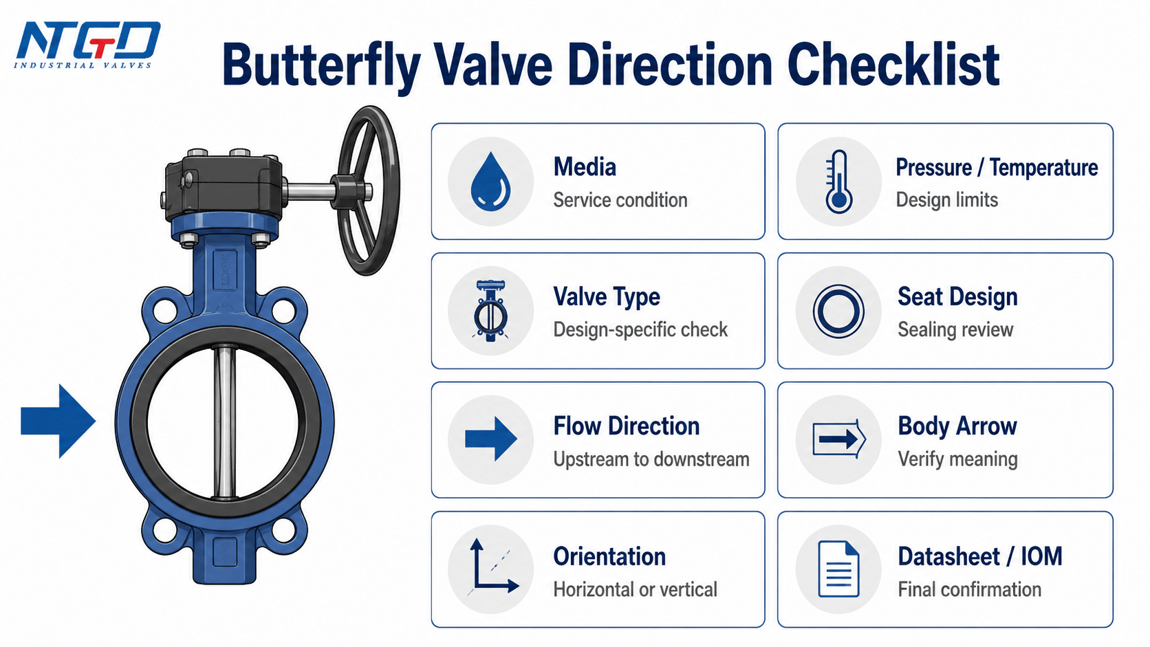
Direction confirmation checklist
| Check item | Why it matters | What to confirm |
|---|---|---|
| Media | Media affects seat, disc, wear and orientation sensitivity | Clean water, gas, slurry, abrasive, corrosive or high-temperature service |
| Pressure / temperature | Direction behavior may depend on service limits | Design pressure, temperature and pressure reversal |
| Valve type | Different designs have different direction sensitivity | Concentric, double-offset, triple-offset, high-performance or metal-seated |
| Seat design | Seat construction affects sealing direction | Resilient seat, metal seat, replaceable seat or special sealing system |
| Flow direction | Defines upstream and downstream | Project flow arrow and line direction |
| Body arrow | May indicate preferred flow or pressure direction | Meaning of arrow confirmed by datasheet or IOM |
| Installation orientation | Horizontal / vertical and shaft position may matter | Pipe orientation, shaft / stem position, actuator clearance |
| Drawing / tag | Prevents wrong valve on wrong line | Tag number, line number, P&ID and layout |
| Datasheet / IOM | Final technical reference for direction and limits | Manufacturer direction, orientation and service notes |
| Supplier confirmation | Needed when documents are unclear | Written clarification before installation or shipment |
For broader valve-style, seat and RFQ checks, use a butterfly valve selection guide together with the direction confirmation checklist.
Preparing these items before RFQ or installation helps the supplier confirm direction-sensitive details early. It also reduces the risk of wrong installation, actuator mismatch, unclear shutoff direction or site rework.
Information to provide for specification review
For engineering review or RFQ communication, provide enough information for the valve supplier to confirm the correct direction and orientation. Useful information includes:
- valve size and pressure class;
- valve type and seat design;
- media and concentration, if applicable;
- operating pressure and temperature;
- normal flow direction;
- possible reverse pressure or backflow;
- required shutoff direction;
- pipeline orientation;
- actuator type and mounting arrangement;
- drawing, tag number or line number;
- any project requirement for bidirectional sealing.
This information helps avoid vague answers such as “the valve is bidirectional” when the real project question is whether the valve can seal and operate correctly under a specific pressure direction.
When to ask for supplier confirmation
Supplier confirmation should be requested when the valve is large, actuated, high-performance, double-offset, triple-offset, metal-seated, used for critical shutoff, installed in a vertical line or exposed to reverse pressure.
It should also be requested when the valve marking and project drawing appear inconsistent. In that case, do not rely on field judgment alone. Confirm the direction before installation.
FAQ
Do butterfly valves have a flow direction?
Yes, many butterfly valves can pass flow in either direction, but the correct direction still depends on design. Standard resilient-seated valves are often less direction-sensitive, while offset, metal-seated, actuated or critical shutoff valves should be checked against the body arrow, datasheet and IOM.
Are butterfly valves bidirectional?
Many butterfly valves are bidirectional in terms of flow path. However, bidirectional flow path does not automatically mean bidirectional shutoff, equal performance in both directions or direction-free installation. For high-performance, metal-seated or offset designs, confirm the preferred pressure side and sealing direction from the datasheet and IOM.
Can a butterfly valve be installed backwards?
A butterfly valve may physically fit into the pipeline even if it is installed backwards, but physical fit does not mean technical correctness. If the valve has a preferred sealing direction, pressure side or body arrow, backwards installation may cause leakage, higher torque, seat wear or field rework.
Which direction do you install a butterfly valve?
Install the butterfly valve so that the project flow direction matches the valve’s required or preferred direction. If the valve has a body arrow, nameplate instruction or datasheet direction note, verify its meaning before installation. For offset, high-performance or metal-seated valves, confirm the direction with the manufacturer or supplier.
What is the orientation of a butterfly valve?
Butterfly valve orientation refers to how the valve is positioned in the pipeline, such as horizontal, vertical, shaft position, stem position or actuator position. Orientation is related to flow direction, but it is not the same thing. Orientation should be checked against the valve design, media condition and IOM.
How do you read the arrow on a butterfly valve?
A butterfly valve arrow may indicate flow direction, preferred pressure direction or installation reference. Do not judge the arrow by appearance alone. Compare the arrow with the project drawing, tag, datasheet and IOM before installation. If the arrow, drawing and datasheet conflict, stop and clarify the direction before installing the valve.
Do triple offset butterfly valves have a preferred flow direction?
Many triple offset butterfly valves are more direction-sensitive than basic resilient-seated butterfly valves. Some designs may support bidirectional sealing, but the preferred flow direction should be confirmed from the product-specific datasheet, IOM and manufacturer guidance. A general butterfly valve flow direction guide should not replace product-specific instructions.
Conclusion
Butterfly valve flow direction should not be reduced to a simple “yes” or “no” rule. Many standard butterfly valves can handle flow in both directions, but the correct installation direction still depends on the valve design, seat construction, pressure side, body arrow, datasheet, project drawing and IOM.
For standard concentric and resilient-seated valves, bidirectional use may often be acceptable in general service. For double-offset, high-performance, triple-offset or metal-seated valves, preferred flow direction and pressure side become more important. In these cases, a wrong installation direction may affect leakage, torque, seat wear or service reliability.
Before installation or RFQ confirmation, engineers and buyers should check the valve type, seat design, flow arrow, orientation, media, pressure / temperature, drawing, tag and supplier documentation. This approach helps prevent field rework and ensures the selected butterfly valve matches the actual pipeline conditions.
Use the direction confirmation checklist above before RFQ finalization or site installation, especially for offset, metal-seated, actuated or critical shutoff butterfly valves.
Application / Specification Support
For project specification review, prepare the media, pressure and temperature range, valve size and pressure class, valve type, seat design, pipeline flow direction, required shutoff direction, possible reverse pressure, installation orientation, actuator arrangement, drawing and tag information.
These details allow an engineering review to check whether the butterfly valve direction, sealing side, orientation and actuator basis match the actual pipeline conditions. They are especially important for double-offset, triple-offset, high-performance and metal-seated butterfly valves, where direction-sensitive details should be confirmed before production, shipment or site installation.
NTGD Valve can support butterfly valve specification review by checking the service conditions, valve design, seat arrangement, actuator requirements and project drawings before final selection.
