
Author Name: Bruce Zheng
Author Role: Co-Founder and Valve Engineer at NTGD Valve
Author Bio: Bruce Zheng is Co-Founder and Valve Engineer at NTGD Valve, focusing on industrial valve selection, application, and technical content for global B2B buyers.
Last Updated: July 5, 2026
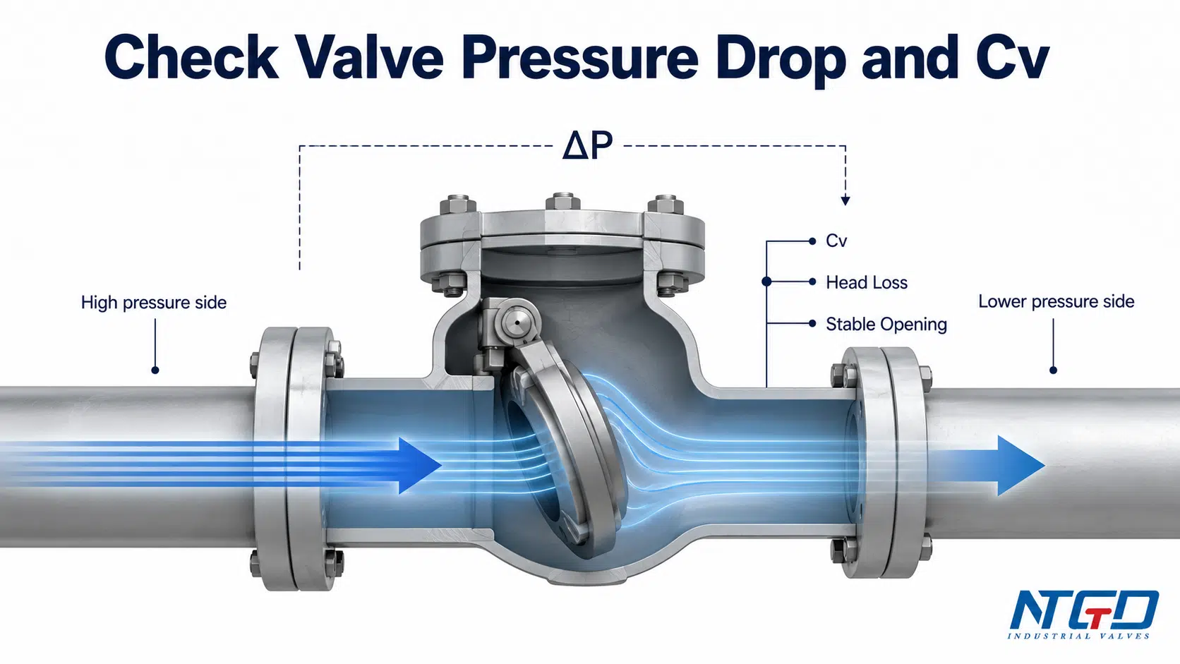
Check valve pressure drop is the pressure difference or energy loss created when fluid passes through a check valve. It is not determined by line size alone. It depends on flow rate, valve design, internal flow path, disc or plate position, medium properties, Cv value, and whether the valve is fully open under real operating conditions.
For industrial piping systems, pressure drop is not only a calculation item. It affects pump head, energy use, stable valve opening, water hammer risk, and final check valve selection. A valve with low catalog pressure drop can still perform poorly in service if the operating flow is too low to hold the valve open, if the cracking pressure is not suitable, or if the valve is installed in disturbed flow.
The practical selection point is simple: pressure drop should be low enough for the system, but the valve must also open stably, close reliably, and match the real operating condition. Final sizing should be checked against the manufacturer’s pressure drop curve, Cv table, head loss chart, or project-specific datasheet.
The article below explains how to separate pressure drop, Cv, head loss, cracking pressure, and type-specific check valve behavior before sending an RFQ or approving a valve for service.
What Is Check Valve Pressure Drop?
Quick definition for industrial piping systems
Check valve pressure drop is the pressure reduction measured across a check valve while fluid is flowing through it. In simple terms, the valve creates resistance. That resistance converts part of the fluid energy into turbulence, velocity change, friction loss, and local losses around the internal closing element.
For a check valve, this resistance is not fixed. It changes with:
- flow rate;
- fluid density and viscosity;
- valve size;
- valve type;
- internal body geometry;
- disc, plate, ball, piston, or spring position;
- installation orientation;
- upstream and downstream flow conditions.
This is why two check valves with the same nominal size can create different pressure drops in the same pipeline.
Why pressure drop matters in pump and process lines
In pump discharge lines, cooling water circuits, fire water systems, industrial water lines, chemical process systems, and other piping networks, check valve pressure loss becomes part of the total system loss. If it is underestimated, the system may not deliver the required flow. If it is overestimated, the project may oversize the pump, pipe, or valve unnecessarily.
A high pressure drop may lead to:
- higher pump head requirement;
- reduced flow at downstream equipment;
- unnecessary energy consumption;
- noise or vibration;
- excessive velocity through the valve;
- unstable check valve behavior.
A very strict low pressure drop requirement can also create a selection trap. It may push the project toward a larger or more open-flow valve, but if that valve cannot reach a stable full-open position at normal or minimum flow, the result may be chatter, accelerated wear, and unstable pressure loss.
Why check valves are different from simple open-bore valves
Some isolation valves, such as full-port ball valves or gate valves in the fully open position, can have a relatively open flow path. A check valve is different because it contains a moving closure element that must respond to flow direction.
Depending on the design, this element may be a swinging disc, dual plates, a guided piston, a spring-loaded disc, a ball, or a nozzle-style non-slam element. Even when the valve is open, part of the internal mechanism remains in or near the flow path.
Because of this internal moving element, treating check valve pressure drop as a generic minor fitting loss without manufacturer verification can lead to undersized pump margin, unstable valve opening, or unexpected system loss.
To connect this pressure-drop discussion with basic valve operation, review how forward flow opens and reverse flow closes the valve in our check valve working principle guide.
Pressure Drop, Pressure Loss, Head Loss and Cv: Terms to Separate First
Before reviewing a check valve Cv value or a head loss chart, it is useful to separate several terms that are often mixed together.
| Term | Meaning in this article | Why it matters | Do not confuse it with |
|---|---|---|---|
| Pressure drop | Pressure difference across the check valve during flow | Used to understand system loss and pump head impact | Pressure rating |
| Pressure loss | General term for pressure reduction caused by resistance | Often used similarly to pressure drop in piping discussions | Permanent valve damage |
| Head loss | Energy loss expressed as height of fluid column, often feet or meters of head | Common in water, pump, and hydraulic calculations | Physical elevation only |
| Cv / flow coefficient | A valve capacity value that relates flow rate and pressure drop under defined conditions | Helps compare flow capacity between valve designs | Product model “CV” or control valve-only sizing |
| Cracking pressure | Differential pressure required to start opening a check valve | Important for low-flow or low-differential-pressure service | Full-open operating pressure drop |
Pressure drop vs pressure loss
In many industrial discussions, pressure drop and pressure loss are used almost interchangeably. Both describe pressure reduction caused by resistance in the valve or piping system. In this article, pressure drop is used when discussing the value across the check valve, while pressure loss is used more broadly for the system effect.
For selection, the key question is not only whether pressure is lost. The important question is whether the loss is acceptable for the required flow rate, pump head, and operating margin.
Head loss in feet of water or meters of head
Head loss expresses the same energy-loss concept in a hydraulic format. Instead of saying a valve creates a certain pressure drop, a water system may describe the same loss as feet of water or meters of head. This is common in pump calculations and water-system documents.
When comparing data, do not mix units without conversion. A manufacturer may present one chart in pressure drop, another in head loss, and another in Cv. The engineer or buyer must confirm that the chart unit, flow unit, and fluid basis match the project.
Cv / flow coefficient as a capacity indicator
Cv is the flow coefficient of a valve. In check valve selection, the check valve flow coefficient is the main capacity term used to relate flow rate, fluid specific gravity, and pressure drop under defined conditions.
A higher Cv generally means the valve can pass more flow at a given pressure drop. However, for check valves, Cv should not be read as the only selection answer. The valve must also open stably, avoid chatter, close correctly, and meet the project’s pressure, temperature, material, and installation requirements.
Cracking pressure is not the same as operating pressure drop
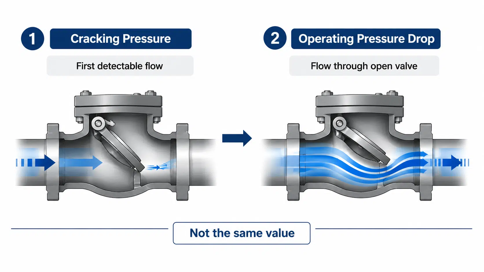
Cracking pressure is the differential pressure at which a check valve begins to open or shows the first indication of flow. It does not mean the valve is fully open. It also does not equal the operating pressure drop at normal flow.
This distinction is critical for check valves. A valve may crack open at a low pressure, but still require sufficient flow to reach a stable open position. If the valve operates partly open for long periods, it may chatter, vibrate, wear the seat or disc, and create more pressure loss than expected.
In low differential pressure service, engineers should verify both cracking pressure and the full-open flow condition. Operating pressure drop alone does not confirm that the valve will open stably or reseat correctly.
What Determines Pressure Drop Across a Check Valve?
Check valve pressure drop is driven by both fluid conditions and valve design. A chart or Cv value is useful only when the operating condition behind it is understood.
| Factor | How it affects pressure drop | Selection note |
|---|---|---|
| Flow rate | Higher flow usually increases pressure drop | Use normal, minimum, and maximum flow, not only design flow |
| Velocity | High velocity increases dynamic loss and may cause noise or wear | Check the recommended velocity range for the valve type |
| Specific gravity | Denser liquids generally require more pressure drop for the same flow and Cv | Confirm the actual medium, not only “water equivalent” |
| Viscosity | Higher viscosity can increase resistance and affect opening behavior | Important for oils, slurries, viscous chemicals, and low-flow systems |
| Valve type | Internal flow path and closure element change resistance | Compare swing, lift, dual plate, silent, piston, and other designs |
| Opening position | A partly open check valve can create higher loss and unstable operation | Verify minimum flow required for stable opening |
| Installation condition | Elbows, pumps, reducers, and disturbed flow can affect valve behavior | Review upstream / downstream piping before final selection |
| Manufacturer design | Same nominal type can vary between brands and models | Use manufacturer data, not generic values |
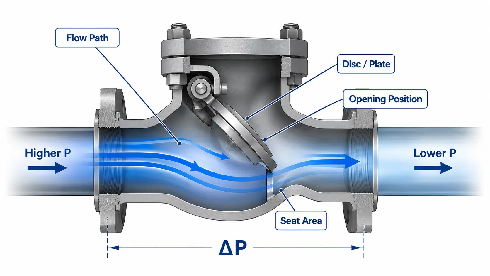
These factors work together. Two check valves with the same nominal size may produce different actual ΔP because their flow path, closure element, spring load, opening angle, and manufacturer design are different. When the flow range, medium, valve type, or opening condition is uncertain, the pressure drop review should be manufacturer-specific.
Flow rate and velocity
Flow rate is the first input for pressure drop review. As flow increases, velocity through the valve also increases, and the pressure drop normally rises. This rise is not always linear. Small increases in flow can create larger increases in pressure loss, especially through compact or internally restricted valve designs.
Velocity also affects valve behavior. Check valves rely on flow to move and hold the closure element open. If velocity is too low, the valve may not open fully. If velocity is too high, the valve may suffer from noise, vibration, erosion, or excessive head loss.
Specific gravity, viscosity and fluid condition
A check valve pressure drop chart is often based on water or a defined test medium. Real industrial fluids may be different. Higher specific gravity, viscosity, suspended solids, gas content, or two-phase conditions can change the actual pressure loss and valve behavior.
For clean water service, chart reading may be relatively direct. For viscous liquids, slurry, corrosive media, or mixed-phase flow, the project should avoid relying only on a generic Cv value. The supplier should review the actual medium and operating range.
Internal flow path, disc position and body design
The body shape and closure element create the local loss inside the valve. A swing check valve may offer a different flow path from a spring-loaded lift check valve. A dual plate wafer check valve may be compact but still has plates and springs in the flow path. A silent or nozzle check valve may control closing behavior but can create a different pressure drop profile.
The name of the check valve type is not enough. The actual body design, seat geometry, guide structure, spring force, and disc travel can change pressure drop.
For a component-level view of how the body, disc, seat, spring and hinge affect movement and sealing, use the check valve parts and components guide.
Whether the valve is fully open or only partly open
A major check valve selection mistake is assuming the valve is always fully open during operation. In reality, if flow is too low, the disc or plate may float in a partly open position. This can increase pressure loss, create noise, and cause wear.
A check valve should be selected for the operating flow range, not only the line size. The normal flow should be high enough to hold the valve open in a stable condition, while the maximum flow should not create excessive pressure drop or velocity.
One of the first questions to ask the manufacturer is: what minimum flow is required for this valve to reach a stable, fully open position in this line size and orientation?
Installation disturbance and upstream flow stability
A check valve installed immediately after a pump, elbow, reducer, tee, or control element may see uneven flow. This can affect disc movement, pressure drop, noise, and closing behavior.
This article does not replace a check valve installation guide, but pressure drop review should include installation conditions. Adequate upstream and downstream piping helps stabilize the flow entering the valve. Detailed installation distance, orientation, and support requirements should be checked against the project installation guide or the manufacturer’s IOM.
For detailed orientation, pump discharge spacing, pipe support and startup checks, refer to the check valve installation guide.
How Cv Relates to Check Valve Pressure Drop
What does Cv mean for a check valve?
Cv is the flow coefficient of the check valve. In check valve selection, it helps estimate how much flow can pass through the valve at a given pressure drop. It is also useful for comparing flow capacity between valve designs of the same nominal size.
However, a check valve Cv value should always be tied to the actual valve design and opening condition. A Cv value from one manufacturer, one valve type, or one size cannot be assumed to apply to another valve.
Basic relationship between flow rate, specific gravity and ΔP
For liquid service, a simplified Cv relationship is useful for preliminary screening. For a given flow rate and fluid specific gravity, an engineer can use the relationship to check whether a valve’s Cv range is likely to meet the allowable pressure drop before requesting the full manufacturer curve.
A common simplified relationship is:
ΔP ≈ SG × (Q / Cv)²
| Variable | Meaning | Needed from | Caution |
|---|---|---|---|
| ΔP | Pressure drop across the valve | Calculation or manufacturer data | Usually expressed in psi or bar, depending on the chart |
| SG | Specific gravity of the fluid | Process data | Water is commonly used as a reference, but real fluids may differ |
| Q | Flow rate | Project operating data | Use normal, minimum, and maximum flow where possible |
| Cv | Valve flow coefficient | Manufacturer datasheet or curve | Must match valve type, size, and design |
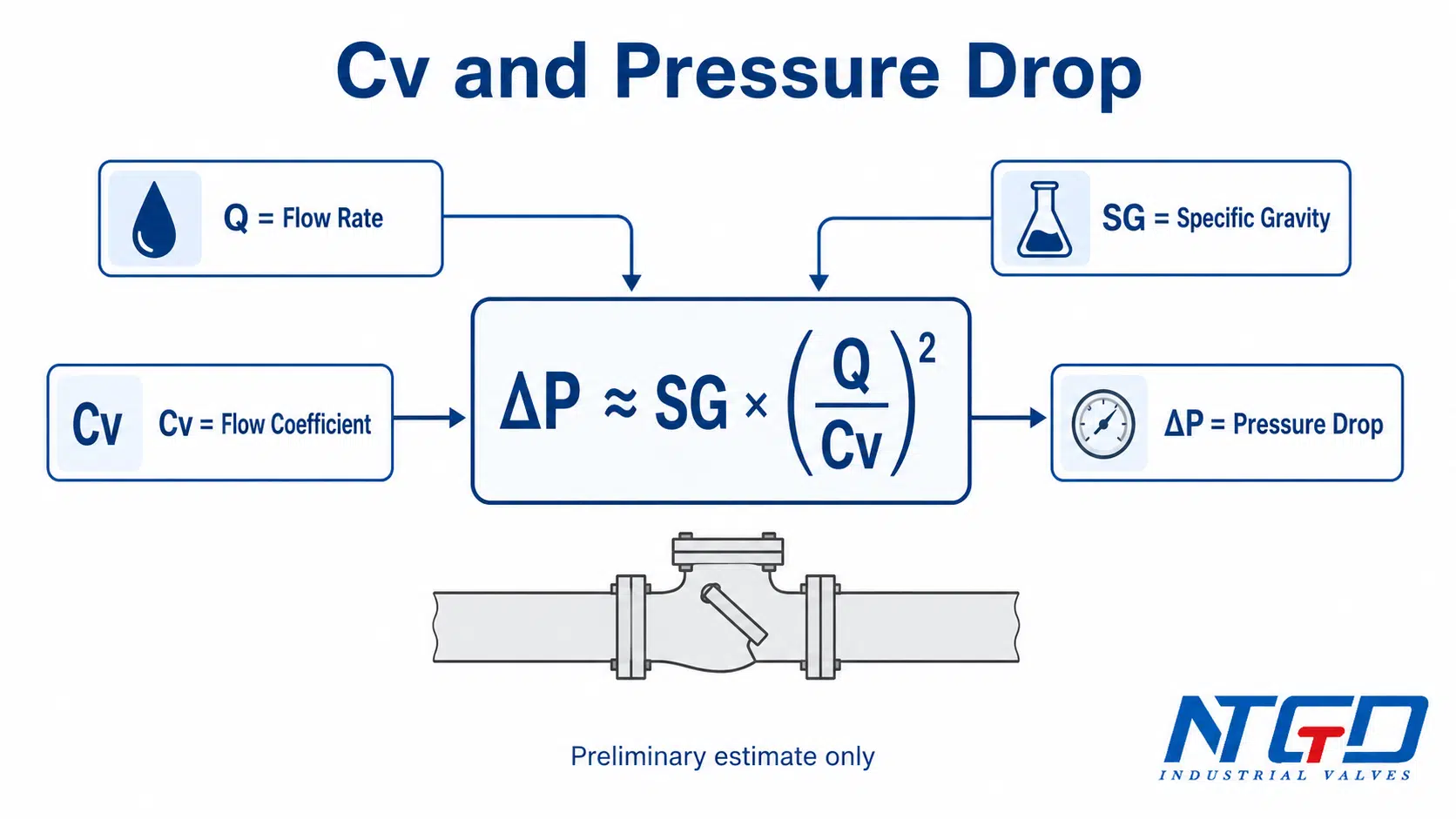
A general Cv flow coefficient reference explains the liquid-service relationship between flow rate, specific gravity and pressure drop; in this article, it is used only as a preliminary check before manufacturer-specific check valve data.
This formula should be treated as a conceptual estimate for clean liquid service under defined conditions, normally assuming a stable, fully open valve. It should not be used as the final sizing basis for gas, steam, high-viscosity liquids, slurry, two-phase flow, or a check valve that may operate partly open or unstably.
Final selection must be checked against the manufacturer’s pressure drop curve, Cv table, datasheet, or test basis for the actual valve design.
Why check valve Cv values must come from manufacturer data
Check valve Cv values are manufacturer-specific. They depend on the internal geometry, travel of the closure element, seat design, spring load, and test basis. Even if two valves are both called “swing check valves,” their Cv values may not be the same.
For RFQ or technical approval, the buyer should request one or more of the following:
- Cv value;
- pressure drop curve;
- head loss chart;
- datasheet with flow capacity;
- recommended flow range;
- minimum flow for stable opening;
- cracking pressure, if relevant to the service.
Why “higher Cv” does not automatically mean better selection
A higher Cv may lower calculated ΔP, but it does not automatically improve check valve selection. If normal flow is below the valve’s minimum stable opening range, the closure element may not stay fully open.
That condition can create chatter, seat or disc wear, unstable pressure loss, and higher long-term maintenance cost. Selection should balance allowable pressure drop with stable opening, closing behavior, flow range, and installation condition.
How to Read a Check Valve Pressure Drop, Cv or Head Loss Chart
Many search results for check valve pressure drop lead to PDFs, head loss charts, Cv tables, or product data curves. These documents can be useful, but they must be read carefully.
| Step | Data to check | Common mistake |
|---|---|---|
| 1 | Valve type and exact model | Using a chart from a different check valve design, leading to inaccurate ΔP estimation |
| 2 | Valve size and end connection | Assuming line size equals correct valve size, which may cause sizing error |
| 3 | Flow rate range | Checking only maximum flow and ignoring normal or minimum flow |
| 4 | Fluid basis | Using water-based data for a different fluid without review |
| 5 | Unit system | Mixing psi, bar, feet of head, meters of head, gpm, or m³/h |
| 6 | Velocity range | Ignoring recommended velocity range, which may lead to chatter, noise, or high loss |
| 7 | Opening condition | Assuming full-open behavior at all flows |
| 8 | Manufacturer source | Treating another manufacturer’s chart as universal |
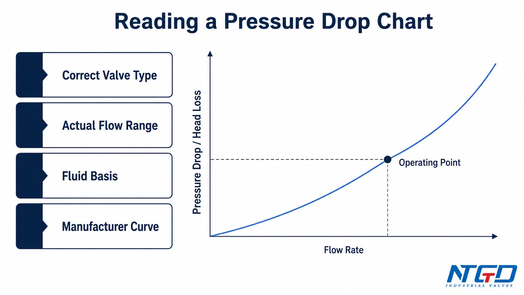
Start with the correct valve type and size
A pressure drop chart is only useful when it matches the valve type and size being considered. A swing check valve chart should not be used for a spring-loaded lift check valve. A wafer check valve curve should not be used for a nozzle check valve. A pressure drop chart from one manufacturer should not be treated as a universal value for all valves.
Match flow rate and operating condition
Pressure drop should be checked at the actual operating flow rate. In many projects, one design flow is not enough. The check valve may see a minimum flow, normal flow, peak flow, startup flow, or pump trip condition. Each can affect valve opening and pressure loss.
For pump discharge service, minimum flow is especially important. A check valve that looks acceptable at maximum flow may chatter at low flow.
Read pressure drop, head loss or Cv consistently
Some charts show pressure drop directly. Others show head loss. Some provide Cv tables instead of curves. The engineer should confirm which value is being used and how it relates to the project calculation.
When reading a check valve head loss chart, pay attention to whether the chart is based on feet of water or meters of head. A head loss chart expresses energy loss in pumping terms, which can be convenient for pump selection. It represents the same physical behavior as a pressure drop curve, but the unit and reading method are different.
For head-loss terminology, the Hydraulic Institute’s valves and fittings minor-loss reference explains how valve and fitting losses are treated as part of system friction loss.
Check velocity range and minimum flow assumptions
Some check valve designs require a minimum velocity or minimum flow to open fully and remain stable. If the chart assumes a stable open position but the actual system operates below that range, the real pressure loss and wear risk may be different.
This is one of the reasons check valve pressure drop review should include both hydraulic data and operating behavior.
Avoid using another manufacturer’s chart as a universal value
A generic chart can help early-stage comparison, but final selection should rely on the manufacturer’s own data for the selected valve. The final RFQ should ask for pressure drop, Cv, head loss, or flow curve information that matches the exact valve design being supplied.
Ignoring installation condition, valve model, flow range, or chart basis can make the chart reading look correct on paper while the actual system performance differs from expectation.
How Check Valve Type Changes Pressure Drop and Head Loss
Different check valve types create different flow resistance. The table below is a selection-support comparison, not a universal ranking. Actual pressure drop must still be verified from manufacturer data.
| Check valve type | Typical flow path / internal feature | Pressure drop tendency | Selection note |
|---|---|---|---|
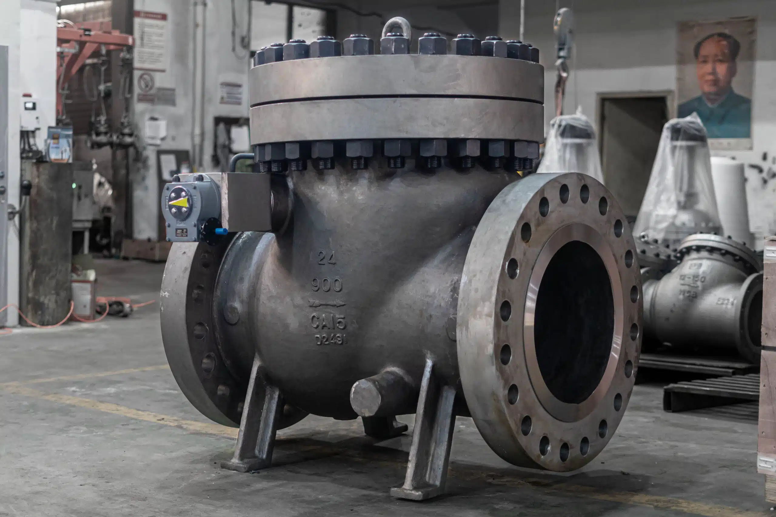
| Swing check valve | Hinged disc swings away from the seat | Generally lower resistance potential when fully open compared with spring-loaded lift designs, but highly dependent on body design and disc stability | Often considered for higher-flow water or process lines, but verify stable opening at normal and minimum flow |
| Spring-loaded check valve | Spring force helps close the disc | Spring load can add opening resistance and affect full-open behavior | Useful where faster closing is required; confirm cracking pressure, Cv, and minimum flow |
| Lift check valve | Guided disc or piston lifts from the seat | Often higher resistance than a simple swing design because the flow path is more restricted | Review carefully where allowable ΔP is tight or flow range varies |
| Piston check valve | Guided piston movement | Can provide controlled movement but may add resistance through the guided path | Suitable for certain pressure / process conditions; verify Cv and full-open behavior |
| Dual plate / wafer check valve | Two spring-assisted plates in compact body | Compact design, but plates and springs influence head loss | Useful where face-to-face space is limited; confirm pressure drop curve for the exact model |
| Silent / nozzle check valve | Designed for non-slam or controlled closing | Pressure drop depends on spring, body profile, and non-slam design | Consider where water hammer or reverse-flow control is critical, not only where lowest ΔP is requested |
| Ball check valve | Ball moves away from seat under flow | Pressure drop depends strongly on body and ball travel | Common in some slurry or wastewater services; verify flow path and solids handling |
| Y-pattern or special check valve | Angled or special internal path | Design-specific | Use exact manufacturer data and application review |
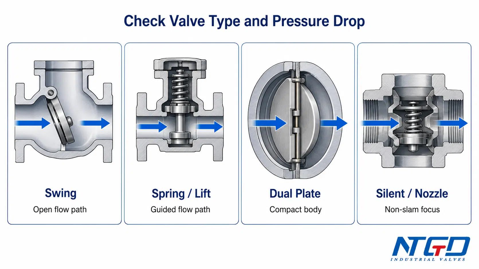
Swing check valves
A swing check valve can offer a relatively open flow path when the disc is fully open. This is why swing check valve pressure drop and head loss are often reviewed for water, wastewater, and pump discharge lines.
However, a swing check valve is not automatically low-loss in every condition. If the flow is too low to hold the disc fully open, the disc may flutter or remain partly open. In that condition, pressure loss and wear can increase.
Spring-loaded, lift and piston check valves
Spring-loaded, lift, and piston check valves may provide more controlled closing behavior, but the spring or guided element can increase flow resistance. These designs should be reviewed with Cv data, pressure drop curves, and minimum flow conditions.
For these valves, cracking pressure and full-open pressure drop should be separated. Cracking pressure tells you when the valve starts opening; it does not confirm the valve is fully open at the operating flow.
For a closer look at spring-assisted closure and non-slam selection boundaries, see the spring loaded check valve selection guide.
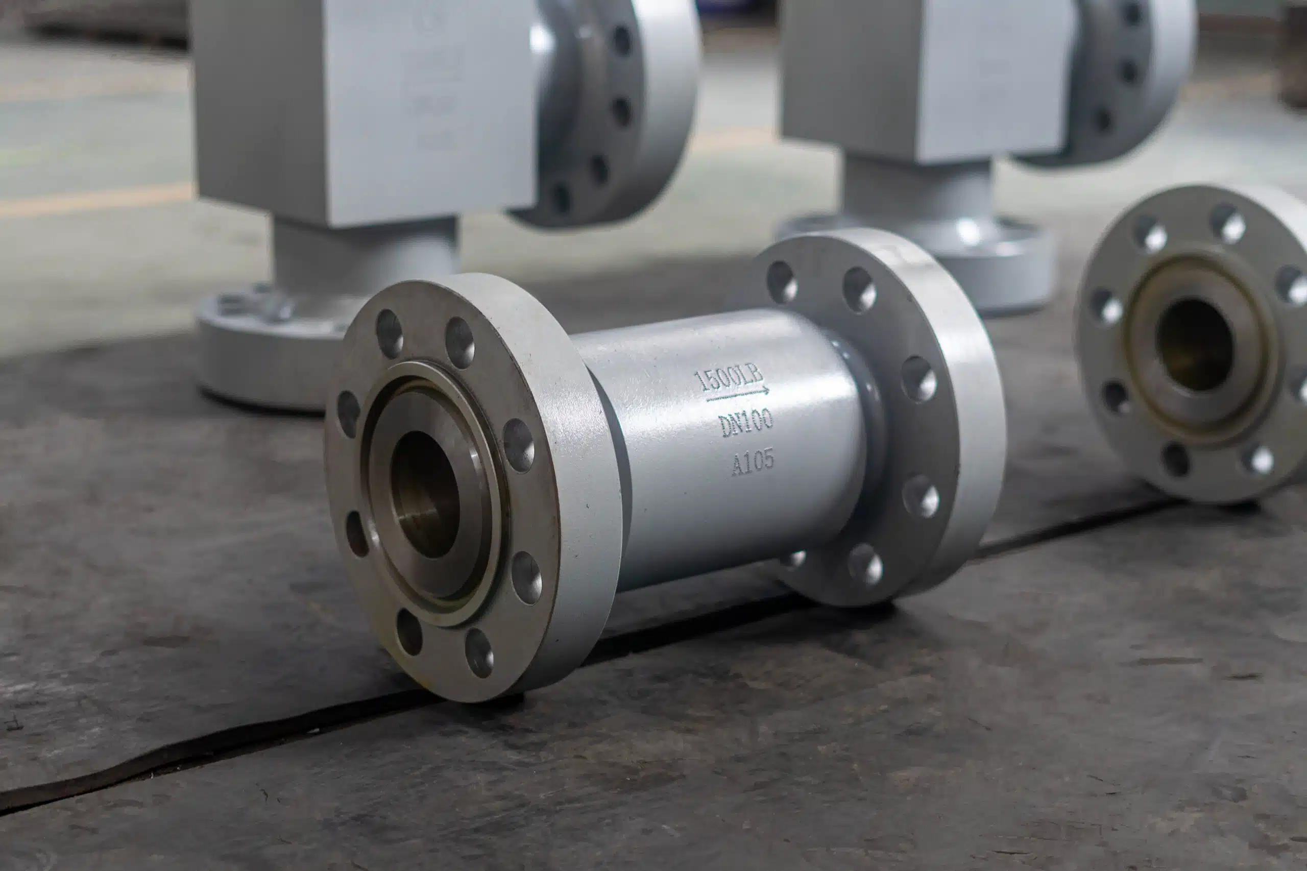
Dual plate and wafer check valves
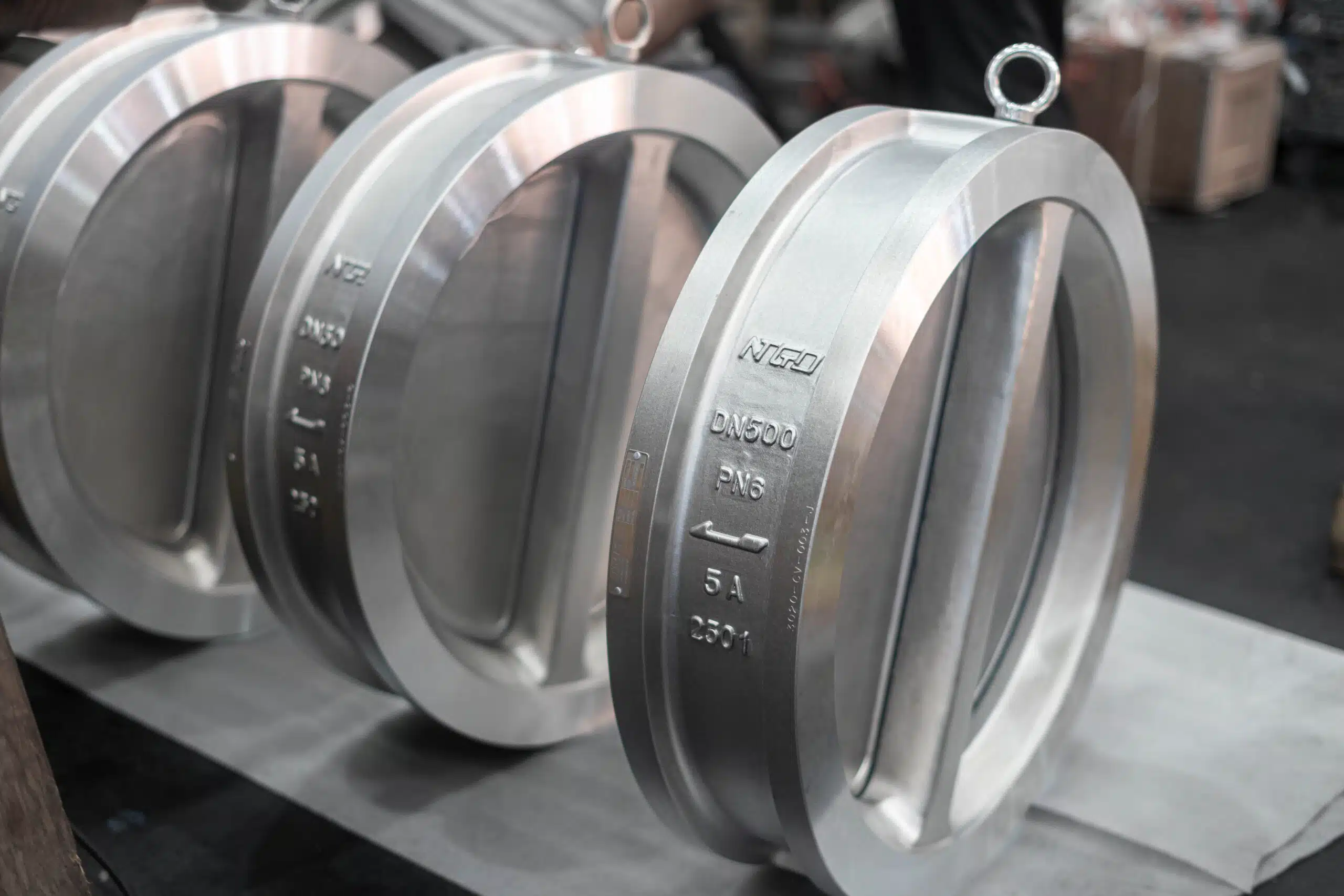
Dual plate and wafer check valves are compact and widely used in industrial piping. They can be useful where face-to-face length is limited. However, the plates, springs, hinge pins, and body profile create a design-specific flow path.
For these valves, chart reading is especially important. The same nominal size can have different pressure drop behavior depending on plate angle, spring design, and body geometry.
Silent, nozzle and non-slam check valves
Silent or nozzle check valves are often selected to reduce slam or improve closure behavior. Their pressure drop must be evaluated together with closing speed, flow stability, and water hammer risk.
A non-slam design may be the better engineering choice even if another valve type appears to have lower pressure drop on a simplified chart. The final decision should consider system behavior, not only one pressure loss value.
Ball, Y-pattern and special check valve designs
Ball check valves, Y-pattern check valves, and other special designs should be reviewed by application. The pressure drop depends heavily on internal passage, ball or disc movement, seat design, and orientation.
These designs should not be selected from a generic type name alone. They require product-specific data.
Why Low Pressure Drop Is Not the Only Selection Target
Low pressure drop is usually desirable, but it should not be the only selection target. A check valve must also open, stay open, close, and reseat correctly.
Oversized valves and unstable opening
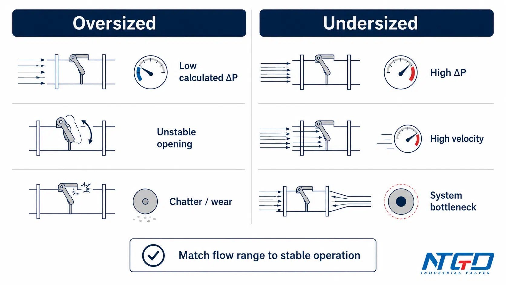
Oversizing can reduce calculated pressure drop, but it may create unstable operation. If the valve is too large for the actual flow, the closure element may not reach a stable full-open position. This can cause chattering, vibration, noise, and accelerated wear.
| Sizing issue | Pressure drop symptom | Operating risk | What to verify |
|---|---|---|---|
| Oversized valve | Low calculated ΔP at design flow, but unstable at normal flow | Chatter and accelerated seat / disc wear, leading to premature leakage and shortened maintenance cycle | Minimum flow for stable opening |
| Undersized valve | Excessive pressure drop | Pump energy penalty, reduced downstream flow, high velocity, erosion, and possible system bottleneck | Allowable ΔP and velocity |
| Wrong valve type | Chart does not match actual service | Misleading selection, unstable operation, or unexpected head loss | Exact type and manufacturer curve |
| Wrong cracking pressure | Valve starts opening too late or too easily | Unstable opening, poor reseal, leakage risk, or premature wear | Cracking pressure and closure requirement |
| Wrong installation condition | Real flow is disturbed | Noise, vibration, inaccurate chart behavior, or shortened component life | Upstream / downstream piping condition |
Undersized valves and excessive pressure loss
An undersized check valve may create high pressure drop and high velocity. This can reduce downstream flow, increase pump load, and create erosion or noise. In severe cases, it can become a bottleneck in the system.
The correct valve size should be based on system flow, allowable pressure drop, line size, velocity, and valve behavior, not only on the nominal pipe size.
Minimum flow, chatter and wear risk
Check valve chatter is often linked to unstable opening. If the flow is not strong enough to hold the disc, plate, piston, or ball in a stable position, the element may move repeatedly. This can damage the seat, hinge, spring, guide, or sealing surface.
A valve with a very low calculated pressure drop may still be a poor selection if the normal flow is below the stable operating range.
An industry discussion in Valve Magazine on check valve sizing and chatter also warns that check valves should be sized for the application, not only line size or the largest Cv value.
Low pressure drop vs low cracking pressure
Low pressure drop and low cracking pressure are related to flow behavior, but they are not the same.
- Low pressure drop describes lower resistance during flow.
- Low cracking pressure describes a lower differential pressure required to start opening the valve.
A low cracking pressure check valve may be useful in low-differential-pressure service, but it still must close reliably and remain stable in operation. The project should not assume that low cracking pressure automatically means low operating pressure loss or better service life.
When a low pressure drop check valve should be requested
A low pressure drop check valve may be appropriate when:
- pump head margin is limited;
- system energy loss must be minimized;
- the service has high flow rate;
- the allowable ΔP across the valve is strict;
- the valve is installed in a long pipeline where cumulative losses matter;
- the process cannot tolerate excessive pressure loss.
In projects with limited pump head margin, a low pressure drop design may be a valid candidate. But it must still meet minimum flow, stable opening, closure, installation, material, pressure, and temperature requirements. Otherwise, the operating risk can be greater than the pressure drop benefit.
Even when these conditions point toward a low pressure drop check valve, the selection should be validated against the manufacturer’s pressure drop curve for the specific model, size, and operating flow range, not just a catalog description.
RFQ Data Checklist for Check Valve Pressure Drop Review
Pressure drop cannot be reviewed from nominal size alone. A useful RFQ should give the supplier enough operating data to check the valve against real flow behavior, not only against a catalog name.
| RFQ data item | Why it is needed | What the supplier should confirm |
|---|---|---|
| Flow rate | Main input for pressure drop and Cv review | Normal, minimum, and maximum flow |
| Medium | Affects density, viscosity, corrosion, and sealing | Compatibility and flow behavior |
| Specific gravity | Required for Cv / ΔP review | Whether water-based data needs correction |
| Viscosity | Can affect pressure loss and opening behavior | Whether standard data is still valid |
| Line size | Affects velocity and fit | Valve size and end connection |
| Valve type | Different designs have different pressure drop | Swing, lift, piston, dual plate, silent, nozzle, etc. |
| Allowable pressure drop | Defines the hydraulic limit | Pressure drop at operating flow |
| Head loss requirement | Important for pump / water system design | Head loss chart or equivalent data |
| Operating pressure and temperature | Defines pressure class and material boundary | Suitable rating and material |
| Cracking pressure | Important for low-flow or low-differential systems | Opening differential, if applicable |
| Orientation | Affects opening, closing, and reseating behavior | Horizontal, vertical up, vertical down, or special condition |
| Installation condition | Disturbed flow can affect stability | Pump discharge, elbows, reducers, straight run |
| Required documents | Needed for approval | Datasheet, drawing, pressure drop curve, test document if required |
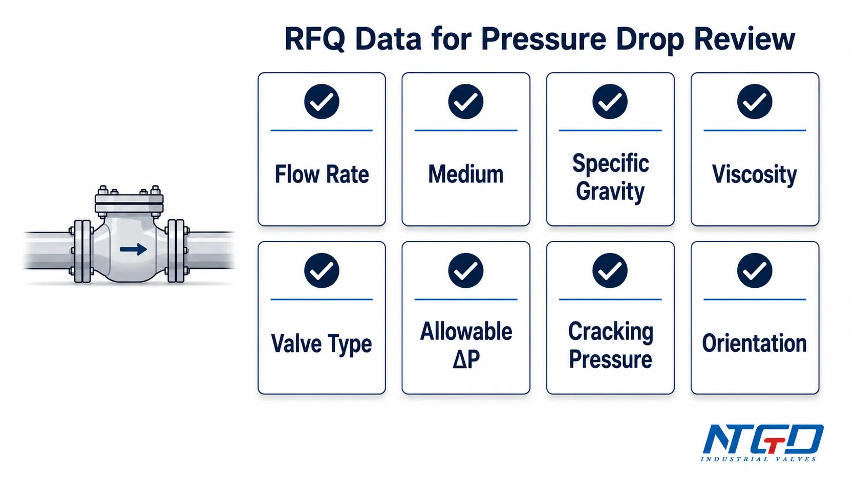
Providing these data allows the supplier or valve engineer to return pressure drop and Cv advice matched to the actual operating condition, not a generic catalog selection.
After the pressure drop, Cv and operating-flow limits are clear, the broader check valve selection guide can help compare valve type, orientation, water hammer risk and RFQ fit.
Flow data and allowable pressure drop
The most useful RFQ input is a real flow range, not only one design point. Minimum flow helps check stable opening. Normal flow helps check everyday pressure loss. Maximum flow helps check velocity and hydraulic limit.
Allowable pressure drop should be stated if the project has a strict limit. If the allowable value is not known, the supplier can still provide pressure drop data for engineering review.
Medium, specific gravity, viscosity and temperature
The pressure drop chart may be based on water or a standard test condition. If the project fluid is oil, slurry, chemical, condensate, seawater, gas, steam, or mixed-phase flow, the supplier should know before selection.
Temperature also matters because it can affect viscosity, material selection, seat design, and pressure rating.
Line size, valve type and installation orientation
Line size alone is not enough. The RFQ should also identify preferred valve type, end connection, pressure class, installation orientation, and whether the valve is installed after a pump, elbow, reducer, or other disturbance.
If the valve must be installed vertically or in a low-flow condition, cracking pressure and reseating behavior may need extra review.
If the installation direction or body arrow is still under review, confirm it with the check valve flow direction guide before final RFQ approval.
Cracking pressure, minimum flow and closure requirement
For check valves, pressure drop review should not ignore opening and closing behavior. A valve must start opening at the correct differential pressure, reach stable opening at normal flow, and close before reverse flow creates damage.
If the system has low differential pressure or intermittent flow, ask the supplier to confirm cracking pressure, minimum flow, and closure performance.
Required datasheet, drawing or pressure drop curve
For technical approval, the buyer may need more than a catalog description. Useful documents include:
- datasheet;
- general arrangement drawing;
- Cv value or Cv table;
- pressure drop curve;
- head loss chart;
- material list;
- test requirement;
- installation note;
- IOM document, if available.
These documents help connect the selected check valve to real operating conditions, not only nominal size and pressure class.
FAQ: Check Valve Pressure Drop, Cv and Head Loss
Is cracking pressure the same as pressure drop?
No. Cracking pressure is the differential pressure required to start opening a check valve. Pressure drop is the pressure loss across the valve during flow. A check valve may crack open before it is fully open, so cracking pressure should not be used as a substitute for operating pressure drop.
What does Cv mean for a check valve?
Cv is the flow coefficient of the check valve. It indicates the valve’s flow capacity under defined conditions. A higher Cv generally means lower pressure drop at the same flow rate, but the valve must still open stably and suit the service conditions.
Is check valve head loss the same as pressure drop?
They describe the same energy-loss concept in different forms. Pressure drop is usually expressed as pressure difference, while head loss is expressed as height of fluid column, such as feet or meters of head. Always check the units before comparing data.
How do you calculate pressure drop across a check valve?
For an initial liquid-service estimate, engineers may use the Cv relationship with flow rate, specific gravity, and valve Cv. The basic inputs are Q, SG, Cv, valve type, and fluid condition. Final validation should use the manufacturer’s pressure drop curve or Cv table for the specific valve model, size, and operating flow range.
Does a check valve reduce pressure?
Yes. Every check valve creates some flow resistance and therefore some pressure loss during flow. In a well-designed system, this reduction is allowed for in the hydraulic calculation. In a poorly selected valve, it can become a noticeable system bottleneck.
Is a higher Cv always better for a check valve?
Not always. A higher Cv can reduce calculated ΔP, but it may not improve the selection if the valve is oversized or cannot stay fully open at normal flow. Minimum flow, stable opening, closure behavior, and system dynamics must be checked together.
When should a low pressure drop check valve be selected?
A low pressure drop check valve may be considered when pump head margin is limited, energy loss is critical, flow rate is high, or the allowable ΔP is strict. It should still be validated against the manufacturer’s curve for the actual model, size, operating flow range, and installation condition.
Do swing check valves have lower pressure drop than spring-loaded check valves?
Often, but only when the swing check valve is fully open and stable. A swing check valve can have a more open flow path than some spring-loaded or lift designs, but actual pressure drop depends on manufacturer design, valve size, flow rate, disc stability, and installation condition.
Conclusion: Match Pressure Drop Data to Real Operating Conditions
Check valve pressure drop is not a single catalog value that can be applied to every system. It is affected by flow rate, Cv, head loss expression, valve type, internal design, medium properties, opening behavior, and installation condition.
For early selection, Cv values, pressure drop charts, and head loss curves can help compare valve options. For final selection, the project should confirm the actual operating flow range, allowable ΔP, medium, valve type, minimum flow, cracking pressure, and manufacturer-specific data.
The best check valve is not simply the one with the lowest pressure drop. It is the valve that meets the hydraulic requirement while opening stably, closing reliably, and fitting the project’s real operating conditions. That is the difference between a catalog match and a reliable engineering selection.
Application / Specification Support
If a misapplied check valve could lead to unstable operation, unexpected energy loss, pump margin issues, or premature wear, NTGD can review the pressure drop, Cv, and operating data before final selection.
Prepare the operating flow range, medium details, specific gravity, viscosity, allowable ΔP or head loss limit, preferred valve type, orientation, and any required datasheet or drawing format. This allows the valve engineer to check whether the selected check valve matches the real piping system instead of relying only on nominal size or a generic chart.
