Author Name: Bruce Zheng
Author Role: Co-Founder and Valve Engineer at NTGD Valve
Author Bio: Bruce Zheng is Co-Founder and Valve Engineer at NTGD Valve, focusing on industrial valve selection, application, and technical content for global B2B buyers.
Last Updated: June 1, 2026
Quick Answer: What Does a Check Valve Do?
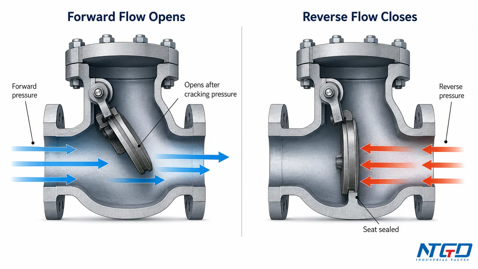
How does a check valve work? A check valve uses pressure differential and an internal closure member to allow forward flow and block reverse flow. When fluid flows in the intended direction, upstream pressure moves the closure member away from the seat. When flow stops, pressure drops, or reverse pressure appears, the closure member returns to the seat and helps prevent backflow.
A check valve is also commonly called a non-return valve or one-way valve. In industrial piping systems, it is often installed to protect pumps, compressors, process lines, tanks, and upstream equipment from unwanted reverse flow.
For buyers comparing terminology, NTGD’s non-return valve guide explains how the same one-way flow function is described in non-return valve documents.
The key point is that a check valve normally operates automatically. It does not require a handwheel, lever, electric actuator, or pneumatic actuator during normal service. Its opening and closing are controlled mainly by pressure differential, flow direction, closure design, and the condition of the sealing surfaces.
For an industrial buyer, this principle is not just a basic definition. If the valve does not open fully, closes too late, seals poorly, or is installed in the wrong direction, the system may lose backflow protection, suffer unstable operation, or experience premature wear.
The Basic Working Principle of a Check Valve
The basic working principle of a check valve is based on the interaction between forward pressure, reverse pressure, and an internal closure member.
Most check valves include several core elements:
- a valve body with an inlet and outlet;
- a seat or sealing surface;
- a closure member, such as a disc, ball, flap, piston, or plate;
- in some designs, a spring, hinge, guide, counterweight, or other closing aid.
In a closed condition, the closure member rests against the seat. When upstream pressure and forward flow are strong enough, the closure member moves away from the seat and allows flow to pass. When flow stops, pressure drops, or reverse pressure appears, the closure member moves back toward the seat and blocks reverse flow.
This is why check valves are often described as self-operating valves. They respond to the condition of the fluid system instead of being manually opened and closed like gate valves, globe valves, or ball valves.
A more accurate explanation is:
A check valve opens when the forward pressure differential is sufficient to move the closure member away from the seat, and it closes when that differential falls or reverses.
For external engineering background on this pressure- and flow-sensitive behavior, Valve Magazine’s flow-sensitive check valve operation discussion is a useful reference.
Unlike powered automatic valves that require an actuator, control signal, or external energy source, a standard check valve operates from the pressure and flow conditions inside the pipeline.
The closure member-seat relationship is critical. If the media contains solids, the service is corrosive, the flow is unstable, or debris collects near the seat, the valve may still move but fail to open smoothly, close tightly, or seal reliably against reverse flow.
How a Check Valve Opens During Forward Flow
A check valve opens when forward flow creates enough pressure force on the inlet side of the valve. This force must be strong enough to overcome the forces keeping the closure member closed.
Those closing forces may include:
- the weight of the disc, ball, flap, or plate;
- spring force in spring-loaded designs;
- gravity in swing or ball-type designs;
- downstream pressure acting against the closure member;
- friction or resistance inside the moving parts.
The combined effect of these closing forces influences the valve’s cracking pressure, opening response, and operating pressure drop. A heavier closure member, stronger spring, unfavorable installation orientation, or higher downstream pressure can all increase the pressure needed to start opening.
The minimum pressure needed to begin opening the valve is commonly called cracking pressure or opening pressure. Once the upstream pressure exceeds this threshold, the closure member starts to move away from the seat.
In a swing check valve, the disc swings open around a hinge.
In a lift check valve or piston check valve, the disc or piston lifts from the seat.
In a ball check valve, the ball moves away from the sealing area.
In a spring-loaded check valve, forward pressure compresses the spring and opens the flow path.
After the valve starts to open, the flow path is not necessarily fully open. Low flow may keep the valve in a partial-open condition for a long period. In that state, the closure member may flutter, contact the seat repeatedly, create chatter, increase local wear, or reduce the valve’s ability to seal cleanly later.
For this reason, opening behavior should be evaluated together with flow rate, pressure differential, valve size, and closure design.
How a Check Valve Closes During Reverse Flow or Pressure Drop
A check valve closes when forward pressure is no longer strong enough to keep the closure member open. This can happen when a pump stops, flow rate decreases, upstream pressure falls, or downstream pressure becomes higher than upstream pressure.
During closing, the closure member moves back toward the seat. The closing action may be assisted by:
- reverse pressure from the downstream side;
- back pressure acting against the closure member;
- gravity;
- spring force;
- the weight of the disc, ball, flap, or plate.
When the closure member reaches the seat, it blocks reverse flow. This is the main reason check valves are used for backflow prevention.
In many industrial systems, reverse flow is not only a flow-direction issue. Delayed closure can allow reverse flow to develop before the closure member seals. That may lead to pump reverse rotation, process media contamination, tank drainage, pressure surge, or damage to upstream equipment.
A check valve should therefore close at the right time and in a controlled way. If it closes too late, reverse flow may occur before sealing. If it closes too suddenly, the system may experience pressure surge or water hammer. These issues usually indicate a mismatch among valve type, closing force, flow deceleration, and system dynamics.
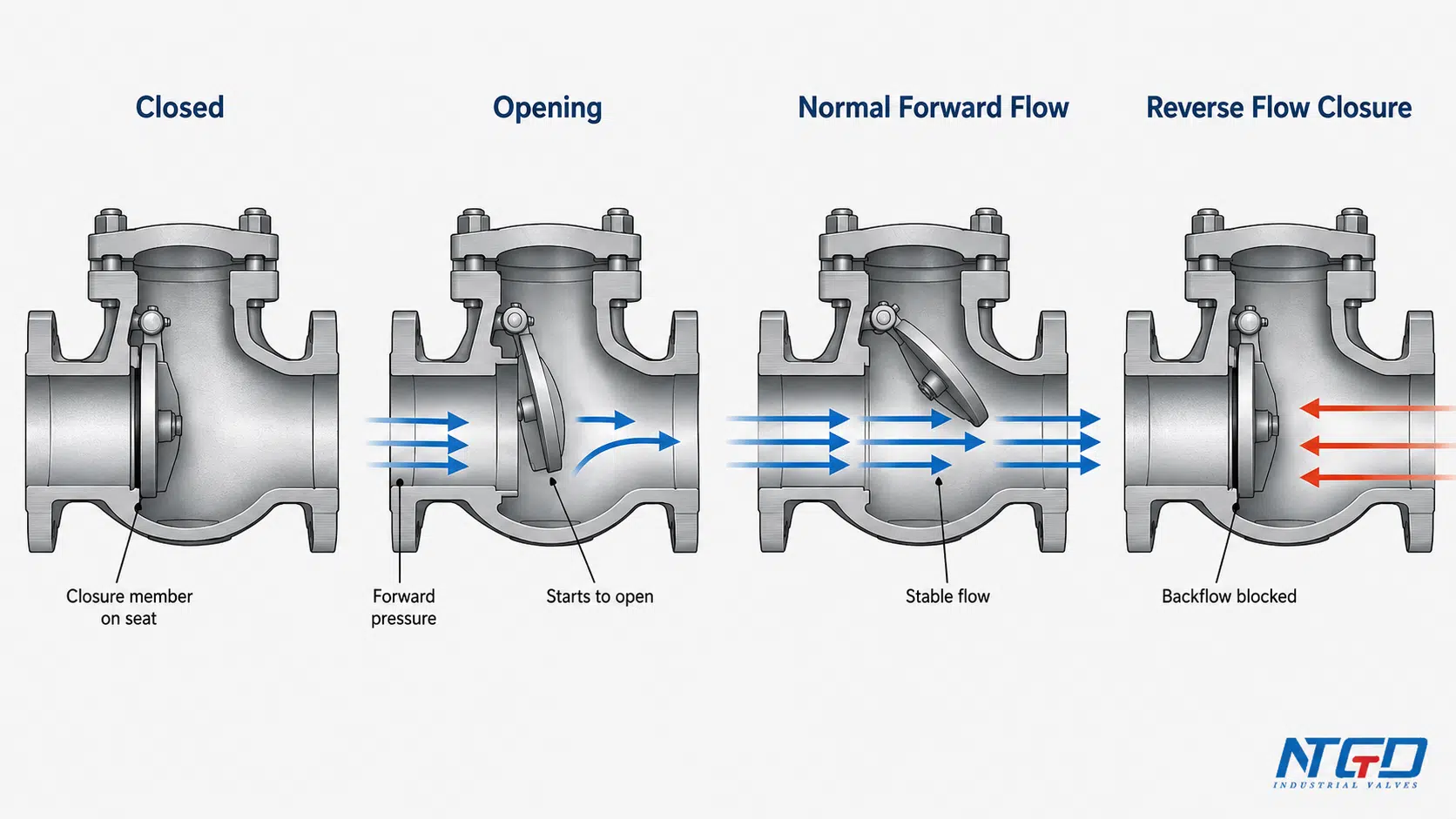
Check Valve Operation Sequence: Closed, Opening, Flowing and Closing
The following table summarizes check valve operation in a typical industrial pipeline.
| Flow condition | Valve response | What happens inside the valve | Engineering meaning |
|---|---|---|---|
| No flow or very low forward pressure | Closed or nearly closed | The disc, ball, flap, or plate remains against the seat | Reverse flow is blocked, but forward flow has not started |
| Forward pressure rises | Starts to open | Upstream pressure begins to move the closure member away from the seat | The pressure differential is approaching or exceeding cracking pressure |
| Normal forward flow | Open | The closure member stays away from the seat while flow continues | Flow passes through the valve in the intended direction |
| Higher stable flow | More fully open, depending on design | The closure member may reach a stable open position | This is the preferred operating condition for most check valves because it reduces the risk of flutter, chatter, and unnecessary pressure drop |
| Reduced or unstable flow | Partially open or unstable | The closure member may move back and forth instead of staying fully open | Oscillation or impact can create chatter, seat wear, fluctuating pressure drop, and unstable operation |
| Flow stops or reverses | Closes | The closure member returns toward the seat | Backflow prevention begins |
| Reverse pressure appears | Sealed closed | Reverse pressure helps press the closure member against the seat | Reverse flow is blocked if the sealing surfaces are suitable and undamaged |
This sequence also explains why check valve operation is different from manual valve operation. A check valve is not switched on or off by an operator in normal service. Its position is governed by flow condition, pressure differential, valve design, and installation.
In systems with frequent pump start-stop cycles or fluctuating flow, a stable operation sequence is especially important. Repeated partial opening and closing can increase pressure fluctuation, shorten sealing life, and raise maintenance frequency.
Cracking Pressure, Flow Rate and Full-Open Behavior
Cracking pressure is the minimum upstream pressure or pressure differential required to start opening a check valve.
It does not mean the valve is fully open. It only means the closure member has begun to move away from the seat and flow has started.
For a technical reference on cracking pressure as the minimum upstream pressure at which a check valve begins to operate, see ScienceDirect’s check valve cracking pressure overview.
Stable full-open behavior still requires enough flow rate and pressure differential to hold the closure member in a steady open position.
This distinction matters in industrial service.
A valve can technically open but still operate poorly if the flow is too low for that valve size or design. In that condition, the closure member may stay partially open or move repeatedly. This can create chatter, noise, pressure drop, and premature wear.
Several factors influence how a check valve opens and reaches a stable position:
- valve size and design;
- closure member weight;
- spring force, if used;
- installation orientation;
- flow rate;
- media density and velocity;
- seat design;
- wear, corrosion, or debris;
- downstream pressure condition.
A low cracking pressure is not automatically better. Lower cracking pressure may reduce the pressure needed to start opening, but the valve still must close positively against reverse flow. Opening threshold and reverse shutoff should therefore be evaluated together.
For this reason, cracking pressure should be checked against the project specification, manufacturer datasheet, and actual service condition rather than assumed from valve type alone.
How Different Closure Members Change the Working Principle
All check valves follow the same basic principle: forward flow opens the valve, and reverse flow or pressure drop closes it. However, the internal closure design changes how that principle is achieved.
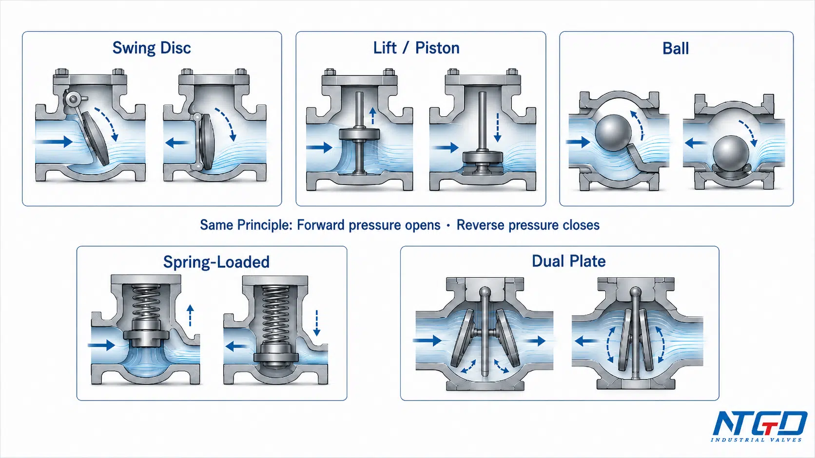
Swing Disc
A swing check valve uses a hinged disc that swings away from the seat during forward flow. When flow stops or reverses, gravity and reverse pressure help the disc return to the seat.
This design can provide a relatively open flow path in suitable services, but the disc needs enough flow to remain stable. If the disc is not fully open, it may flutter, slam, or create additional pressure loss.
For a deeper product-level view of this hinged-disc design, NTGD’s swing check valve page explains its working principle, structure, applications, and installation considerations.
Lift Disc or Piston
A lift check valve or piston check valve uses a disc or piston that moves vertically or axially away from the seat. Forward pressure lifts the closure member, and reduced pressure allows it to return.
This design can provide controlled movement and reliable seating, but the flow path and installation orientation should be checked carefully because both can influence pressure drop and closing behavior.
For guided-disc services such as steam, boiler feedwater, or pump discharge, NTGD’s piston check valve page explains controlled linear movement and sealing behavior in more detail.
Ball
A ball check valve uses a ball as the closure member. Forward pressure moves the ball away from the seat, while reverse flow, gravity, or spring force returns it to the sealing position.
Ball check valves may tolerate certain media conditions better than some guided designs, but suitability is still governed by media, pressure, orientation, cracking pressure, and seat construction.
Spring-Loaded Closure
A spring-loaded check valve uses a spring to help the valve close faster and more predictably. Forward pressure must overcome spring force before the valve opens.
The same spring that assists faster closure also increases the minimum pressure needed to open the valve. For this reason, cracking pressure and closing speed must be evaluated together.
Dual Plate, Nozzle or Silent Designs
Dual plate, nozzle, axial flow, or silent check valve designs use different closing geometries to improve response time, reduce slam, or suit specific pipeline conditions.
These designs should not be selected only by name. The buyer should consider flow rate, pressure class, installation position, media, shutoff requirement, and the risk of water hammer or reverse flow.
Regardless of the closure design, the working principle remains the same: forward pressure must open the valve, while reverse pressure, gravity, spring force, or other closing forces must return the closure member to the seat.
This section is only a working-principle overview. A complete check valve types comparison should be handled separately, because each design has its own application range and selection logic.
For a broader comparison of closure designs and applications, see NTGD’s check valve types guide.
Why Check Valve Working Principle Matters in Industrial Systems
The working principle of a check valve affects more than one-way flow. It can influence equipment protection, process stability, safety, and long-term maintenance.
In pump discharge lines, timely closure helps prevent downstream fluid from flowing backward after pump shutdown. If the valve closes too slowly or does not seal properly, reverse flow may contribute to pump reverse rotation or mechanical stress.
In process pipelines, reliable seat sealing and reverse-flow closure help prevent media from returning into upstream equipment, tanks, or other process lines. This can reduce the risk of contamination, unintended mixing, or pressure imbalance.
In wastewater, slurry, or solid-laden service, the valve’s closure design and seat area become especially important. Debris or solids may prevent tight closure if the valve design is not suitable for the media.
In chemical, power, oil and gas, marine, and general industrial systems, the check valve must be matched to the actual operating condition. A valve that works well in clean water may not behave the same way in viscous media, high-temperature service, or cyclic pump operation.
Many field problems are not caused by the basic idea of a check valve, but by a mismatch between the valve’s working principle and the actual system dynamics.
The key point is simple:
Check valve selection is not only about preventing reverse flow. It is also about whether the valve can open fully, close reliably, and remain stable under real pipeline conditions.
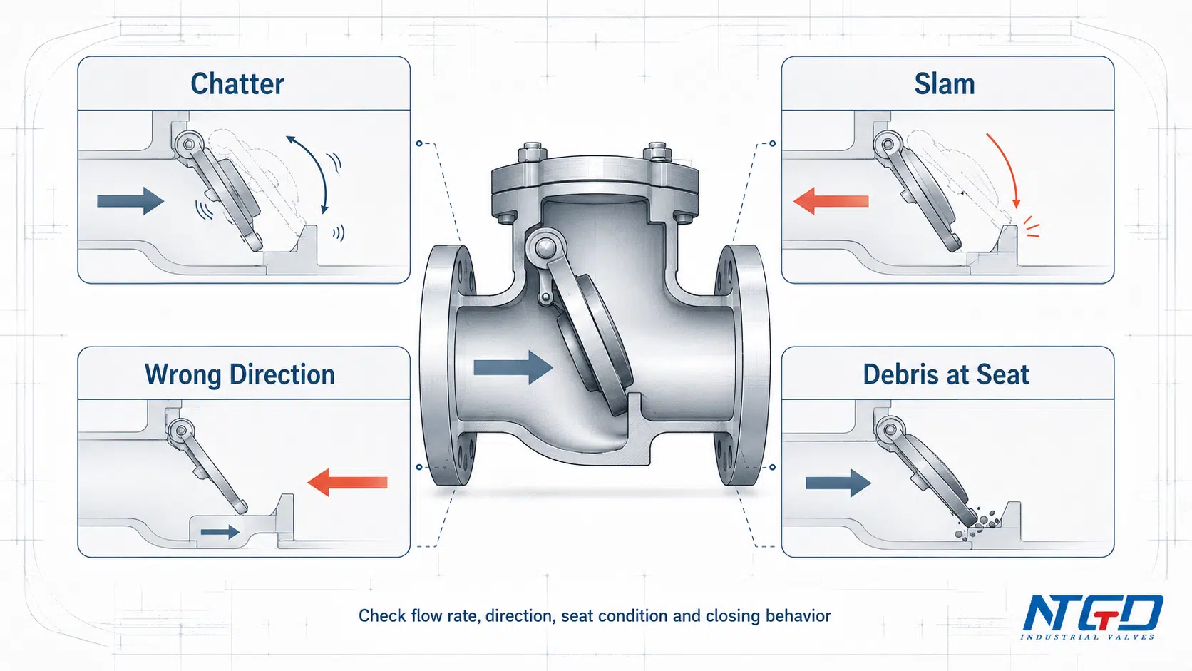
Common Operation Risks: Chatter, Slam, Wrong Direction and Debris
A check valve may have a simple function, but poor application can create operating problems. The table below summarizes common principle-related risks.
| Condition | Possible cause | Principle-related explanation | What to check |
|---|---|---|---|
| Chatter or repeated opening and closing | Low flow, oversized valve, unstable pressure | The closure member cannot stay in a stable open position and repeatedly moves toward and away from the seat | Flow rate, valve size, pressure drop, valve type |
| Valve slam or water hammer | Sudden flow reversal or delayed closure | The closure member closes too late or too quickly under reverse flow, causing a rapid change in flow momentum | Pump shutdown sequence, valve closing speed, system water hammer tolerance, pipeline length, and valve design |
| Leakage or reverse flow | Worn seat, debris, damaged closure member | The closure member cannot seal properly against the seat | Seat condition, debris, corrosion, shutoff requirement |
| Valve does not open properly | Insufficient upstream pressure or wrong cracking pressure | The opening force from upstream pressure is lower than the combined closing force from gravity, spring force, friction, or downstream pressure | Cracking pressure, spring force, flow rate, downstream pressure |
| Valve installed backwards | Incorrect flow direction | Forward flow pushes against the closed side of the valve | Body arrow, drawing, datasheet, installation direction |
| Excessive pressure drop | Valve not fully open or unsuitable flow path | Flow passes through a restricted opening | Valve type, flow rate, bore design, application condition |
If valve slam or water hammer risk is a main concern, compare this working principle with NTGD’s non-slam check valve design before final specification.
These issues do not always mean the valve itself is defective. In many cases, the root cause is a mismatch between valve design and system condition.
Unchecked chatter or slam may accelerate seat wear, damage nearby equipment, increase maintenance frequency, or contribute to unplanned downtime.
For water-hammer context, Waterhammer.com’s check valve slam and water hammer discussion explains why limited reverse flow before closure can still create surge risk.
For this reason, unstable valve movement should be treated as an application and system-design warning, not just a noise problem.
This article is not a troubleshooting guide, but the working principle explains why unstable flow, wrong sizing, incorrect orientation, contaminated media, or worn sealing surfaces can affect check valve performance.
What Information Helps Select the Right Check Valve After Understanding the Principle?
After understanding how a check valve works, the next step is to match the valve to the actual service condition.
For an industrial application, the buyer or engineer should usually prepare:
- media type, including whether it is clean, corrosive, viscous, or solid-laden;
- operating pressure and temperature;
- maximum and minimum flow rate;
- installation orientation;
- flow direction;
- required cracking pressure or opening pressure;
- shutoff or reverse leakage requirement;
- valve type preference or project specification;
- end connection;
- body and trim material requirements;
- pipeline size and pressure class;
- pump start / stop condition;
- risk of water hammer, slam, or pressure surge;
- applicable project standards and datasheets.
This information helps determine whether a swing check valve, lift check valve, piston check valve, dual plate check valve, spring-loaded check valve, silent check valve, or another design is more suitable.
The working principle is the starting point. Final valve selection should still be checked against the project specification, service condition, and manufacturer’s technical data.
FAQ
What is a check valve and how does it work?
A check valve works by using pressure differential and an internal closure member to allow flow in one direction and block reverse flow. Forward pressure opens the valve; pressure drop or reverse pressure closes it against the seat.
Are check valves normally open or closed?
Most standard industrial check valves are closed when there is no forward flow. They open only when upstream pressure or forward flow is strong enough to move the closure member away from the seat.
How much pressure is needed to open a check valve?
The pressure needed to start opening a check valve is called cracking pressure or opening pressure. The exact value is determined by valve design, size, spring force, closure member weight, installation orientation, and service condition, so it should be checked against the manufacturer datasheet or project specification.
What causes a check valve to open and close?
A check valve opens when forward pressure differential is strong enough to move the closure member away from the seat. It closes when forward pressure drops, flow stops, or reverse pressure pushes the closure member back toward the seat.
What happens if a check valve is installed backwards?
If a check valve is installed backwards, normal forward flow may be blocked or severely restricted. It may also fail to protect the system from reverse flow in the intended direction. The body flow arrow, drawing, and datasheet should be checked before installation.
How do you know if a check valve is working?
A working check valve should allow forward flow and prevent reverse flow within its design limits. Possible warning signs include backflow, leakage, abnormal noise, chatter, pressure drop, or failure to open under expected flow conditions. Confirmed reverse flow or leakage should trigger inspection or isolation according to the site procedure.
Can a check valve prevent water hammer?
A check valve can help reduce reverse flow, but it is not a guaranteed water hammer solution by itself. Water hammer risk is influenced by valve type, closing speed, pump shutdown behavior, flow velocity, and pipeline layout.
Is a check valve the same as a non-return valve?
In many industrial contexts, “check valve” and “non-return valve” describe the same basic function: allowing flow in one direction and preventing reverse flow. The preferred term may vary by region, project specification, or valve type.
What is the difference between a check valve and a backflow preventer?
A check valve is a valve that prevents reverse flow in a pipeline. A backflow preventer may refer to a broader device or assembly used in specific systems to prevent contamination or unwanted reverse flow. The exact distinction depends on the application and local requirements.
Why does a check valve chatter or slam?
Chatter usually occurs when flow is too low or unstable to hold the closure member fully open. Slam may occur when reverse flow or pump shutdown causes the valve to close suddenly. Both issues are often related to valve sizing, flow condition, closing speed, and system dynamics.
Conclusion
So, how does a check valve work in an industrial pipeline? It responds to flow direction and pressure differential. Forward flow opens the valve when the upstream pressure is sufficient. When flow stops, pressure drops, or reverse flow appears, the closure member returns to the seat and helps prevent backflow.
The main engineering concepts are normally closed operation, cracking pressure, closure member movement, seat sealing, and reverse pressure closure. These principles explain why the same check valve may perform differently under different flow rates, media conditions, installation orientations, and system dynamics.
For industrial service, the best check valve is not simply the one that “allows one-way flow.” It is the valve that opens fully enough, closes reliably, and remains stable under the actual operating condition.
Understanding how a check valve works is the foundation for correct selection, installation review, and long-term system reliability.
Application / Specification Support
If you are selecting a check valve for an industrial pipeline, prepare the media, pressure, temperature, flow rate, installation direction, cracking pressure requirement, shutoff expectation, valve type preference, end connection, and material requirements before technical review.
After the working principle is clear, these parameters help the supplier or engineering team match the valve to real operating conditions instead of selecting only by valve name or nominal pipe size.
For broader service-condition review before RFQ, NTGD’s industrial valve selection guide can help organize media, pressure, temperature, sealing, and application data.
NTGD Valve can support check valve selection for industrial applications where reverse flow protection, pressure class, media condition, and installation requirements must be evaluated together.
