Nom de l'auteur : Bruce Zheng
Rôle de l'auteur : Cofondateur et ingénieur en vannes chez NTGD Valve
Bio de l'auteur : Bruce Zheng est cofondateur et ingénieur en vannes chez NTGD Valve, qui se concentre sur la sélection des vannes industrielles, les applications et le contenu technique pour les acheteurs B2B mondiaux.
Dernière mise à jour : June 22, 2026
Quick Answer: What Is Ball Valve Torque?
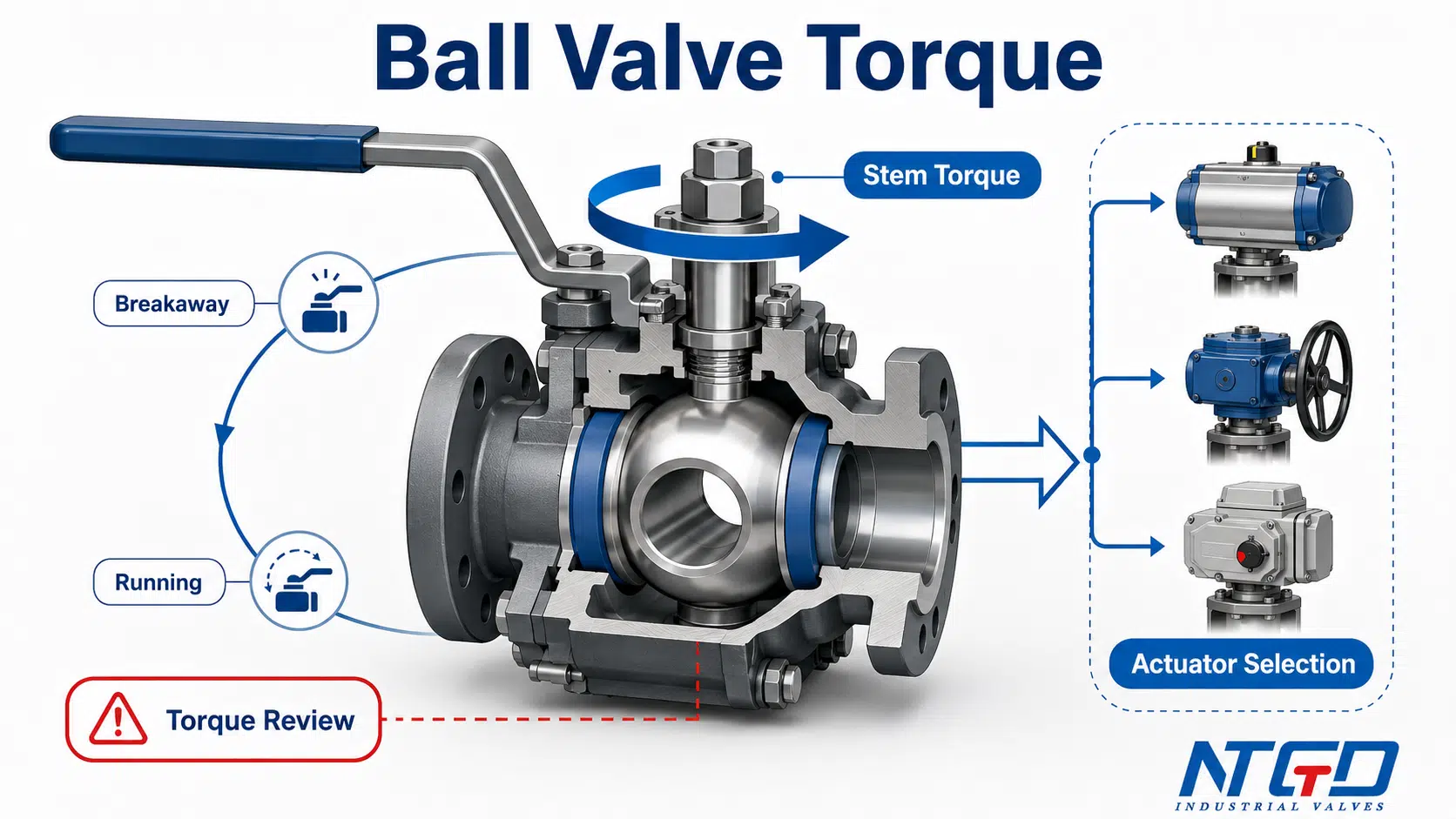
Ball valve torque is the rotational force required to turn the ball inside a ball valve through its operating cycle. It is the force needed to move the valve from closed to open, from open to closed, or through an intermediate operating position. When an engineer needs to check manual operation, select a gearbox, or size a pneumatic or electric actuator, ball valve torque is one of the first data points that must be confirmed.
For industrial selection, ball valve torque should not be treated as one fixed number. Breakaway torque, running torque, end torque, seating torque and re-seat torque can be different because the ball, seats, stem packing, bearings, pressure load and service conditions do not create the same resistance at every point of rotation. Ignoring these torque-stage differences can lead to actuator undersizing, incomplete valve travel, poor shutoff or excessive torque applied to the stem.
Torque data is especially important when selecting a manual handle, gearbox, pneumatic actuator or electric actuator. A torque chart or rough estimate can help during early review, but final actuator selection should be based on manufacturer-confirmed torque data for the exact valve size, pressure class, seat material, design, media, temperature and differential pressure. This article explains torque stages, torque factors, chart interpretation and actuator selection basics; it does not provide a universal torque values table or an online torque calculator.
What Is Ball Valve Torque?
Ball valve torque should be treated as a selection input, not only as a catalog data point. It describes the turning force required to rotate the ball inside the valve body. In a typical quarter-turn ball valve, the ball rotates approximately 90 degrees between the fully closed and fully open positions. During this rotation, the stem transfers torque from a handle, gearbox or actuator to the ball.
In simple terms, torque answers one practical question:
How much turning force is required to operate this ball valve safely and reliably under the specified service conditions?
That question matters because a valve that is easy to turn in one service may require much higher torque in another service. A small soft-seated ball valve in clean water service is not the same as a larger metal-seated ball valve in high-pressure, dry gas, slurry or high-temperature service.
Ball Valve Torque vs Operating Torque
In many project discussions, the terms ball valve torque et ball valve operating torque are used close to each other. However, they should be handled carefully.
Ball valve torque is the general topic. It may refer to any torque value associated with the valve.
Couple de fonctionnement usually means the torque required to operate the valve through its stroke under a defined condition. It may include the starting torque, running torque and closing or seating torque, depending on how the manufacturer presents the data.
For actuator selection, it is not enough to ask only for “operating torque” without context. The specification should clarify whether the value refers to breakaway torque, running torque, end torque, maximum operating torque, or a manufacturer-defined torque requirement.
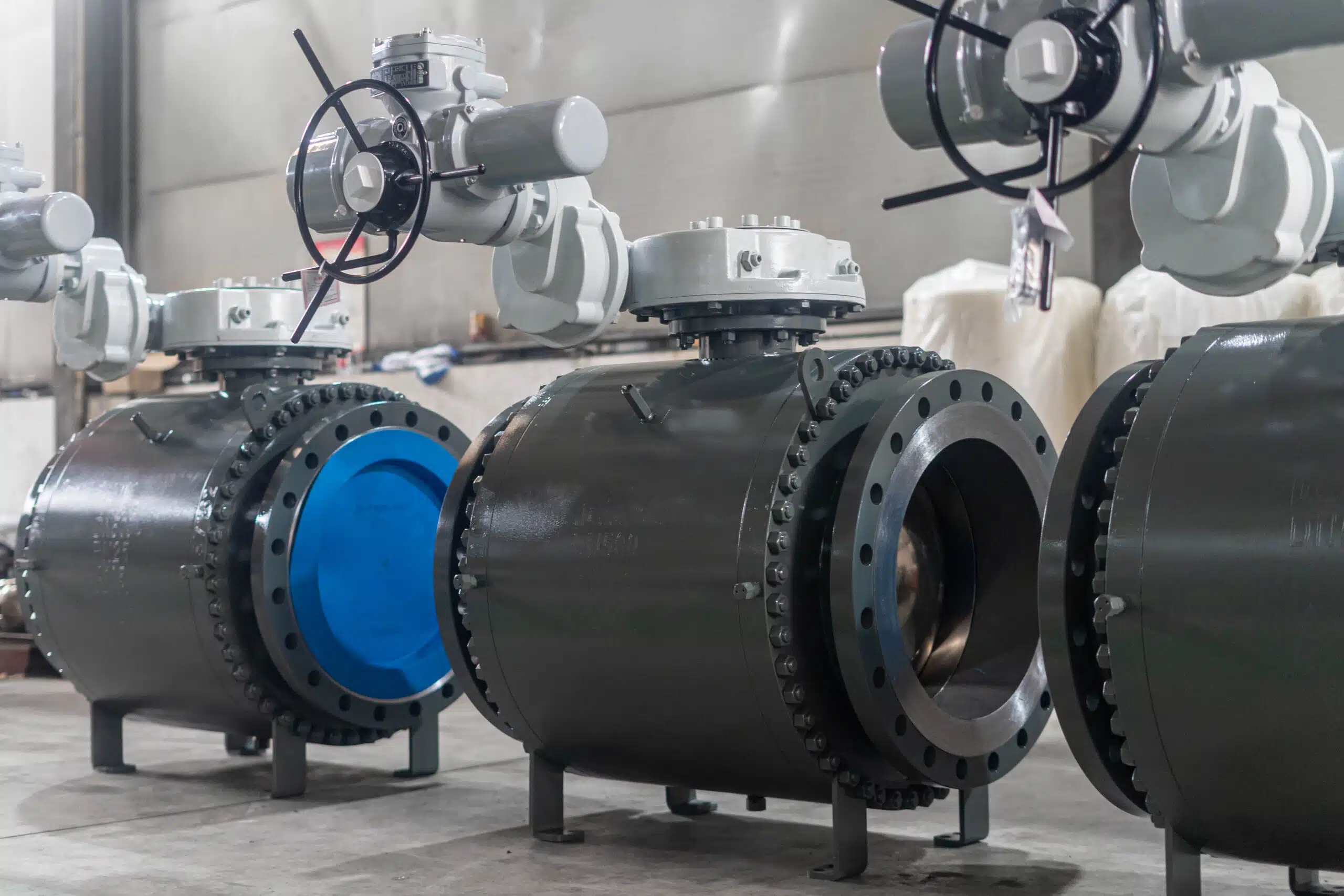
Why Torque Matters for Manual, Gear and Actuated Ball Valves
Torque affects several practical decisions:
| Mode opératoire | Why torque matters | Impact de la sélection |
|---|---|---|
| Poignée manuelle | Determines whether the valve can be operated safely by hand | A high-torque valve may require a longer handle, gearbox or actuator |
| Opérateur d'engrenages | Reduces manual effort but adds mechanical selection requirements | Gearbox selection must match valve torque and service duty |
| Actionneur pneumatique | Actuator output changes with air supply, spring force and actuator design | Valve torque must be checked against actuator output at required supply pressure |
| Actionneur électrique | Output torque, speed, voltage and control type must suit the valve | Undersized electric actuators may stall or trip under load |
| Automated package | Valve torque affects reliability, response and fail-safe function | Torque margin and service factor must be reviewed before order confirmation |
If the project requires the valve and actuator to be supplied as one automated package, use the torque review in this article before moving to an robinet à boisseau sphérique actionné specification.
Torque is not only an actuator issue. It also affects operator safety, opening reliability, emergency shutoff, cycling duty and the risk of overloading the stem or drive train.
Published Torque Data vs Actual Operating Torque
Published torque data is usually based on defined test or reference conditions. Actual operating torque can change after installation because the valve is exposed to real service conditions.
A torque value may be affected by:
- pressure load across the closed ball;
- seat material and seat preload;
- media cleanliness, viscosity or dryness;
- temperature effects on seats and seals;
- corrosion, scale, deposits or polymerization;
- stem packing friction;
- operation frequency and long standstill periods;
- whether the valve is floating ball or trunnion mounted.
Published torque data is useful for early screening and preliminary actuator review, but it should not be treated as the final value for every service. Final selection should use manufacturer-confirmed torque data for the exact valve configuration and the actual service data, including media, temperature, maximum differential pressure, seat material and operating frequency.
For broader industry background, this quarter-turn valve torque overview explains why published torque values may not fully represent actual installation and operating conditions.
Breakaway Torque, Running Torque and Re-seat Torque
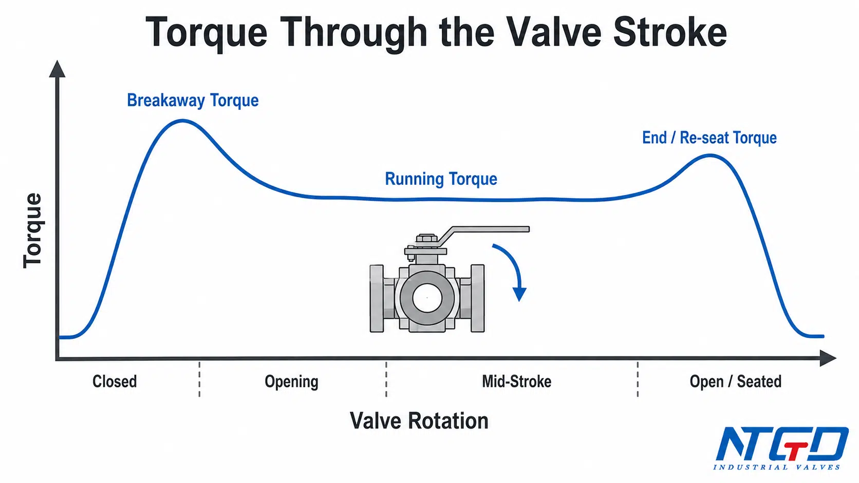
A ball valve does not usually require the same torque at every point of the 90-degree rotation. The torque profile changes as the ball starts moving, continues rotating and reaches the final sealing position.
The most important terms are breakaway torque, running torque, end torque, seating torque et re-seat torque.
Breakaway Torque / Break-to-Open Torque
Breakaway torque is the torque required to start moving the ball from a stationary position. In many actuator sizing discussions, this is one of the most important values because the valve must first overcome static friction before the ball begins to rotate.
Breakaway torque may be high because the ball and seats have been pressed together under differential pressure. If the valve has remained closed for a long time, deposits, seat compression or media effects may also increase the initial force required to move the ball.
For actuator selection, breakaway torque is a key check for actuator start capability. If the actuator cannot overcome the required breakaway torque at the start of the stroke, the valve may fail to open or close even if the actuator appears adequate on a catalog rating.
Running Torque / Run Torque
Running torque is the torque required to keep the ball moving after it has already started rotating. It is often lower than breakaway torque, but this relationship is not universal. The exact value depends on valve design, seat material, media, pressure and the manufacturer’s torque data.
Running torque matters because the actuator must continue to rotate the ball through the stroke, not only start the movement. If an actuator has enough starting torque but insufficient output during the mid-stroke range, the valve may stop before reaching the required open or closed position.
End Torque, Seating Torque and Re-seat Torque
At the end of the stroke, the ball reaches the fully open or fully closed position. Depending on the direction of operation and the manufacturer’s terminology, the required torque may be described as end torque, seating torque, closing torque ou re-seat torque.
For a soft-seated ball valve, seating or re-seat torque can be affected by how the ball compresses against the seat. For a metal-seated ball valve, the final sealing interface may require different torque behavior, especially in high-temperature or abrasive service.
For shutoff service, final seating torque cannot be ignored. If the actuator does not provide enough torque near the end of the stroke, the valve may not fully reach the required sealing position, which can cause poor shutoff, leakage risk or excessive stress on the sealing surface.
BTO, RTO, ETO, BTC, RTC and ETC Explained
Some torque charts and actuator sizing documents use abbreviations to describe torque at different points in the opening or closing cycle.
| Abbreviation | Common meaning | Mode d'emploi | What it represents | Pourquoi c'est important |
|---|---|---|---|---|
| BTO | Break to open | Ouverture | Torque required to start opening from closed position | Critical for actuator start capability |
| RTO | Run to open | Ouverture | Torque required while the valve continues opening | Confirms actuator output through the stroke |
| ETO | End to open | Ouverture | Torque near the fully open position | Helps confirm full travel capability |
| BTC | Break to close | Fermeture | Torque required to start closing from open position | Important for fail-close or closing duty |
| RTC | Run to close | Fermeture | Torque required while the valve continues closing | Relevant for cycling and control sequence |
| ETC | End to close | Fermeture | Torque near the fully closed / seated position | Important for final shutoff and seating |
Terminology can vary by manufacturer. Always confirm the abbreviation definitions on the specific valve torque chart or actuator selection document.
Actuator selection should compare the valve torque requirement at the critical torque points with the actuator output at the corresponding stroke positions. This is especially important for spring-return actuators and actuator designs where torque output is not constant through the full travel.
Why Ball Valve Torque Changes During Operation
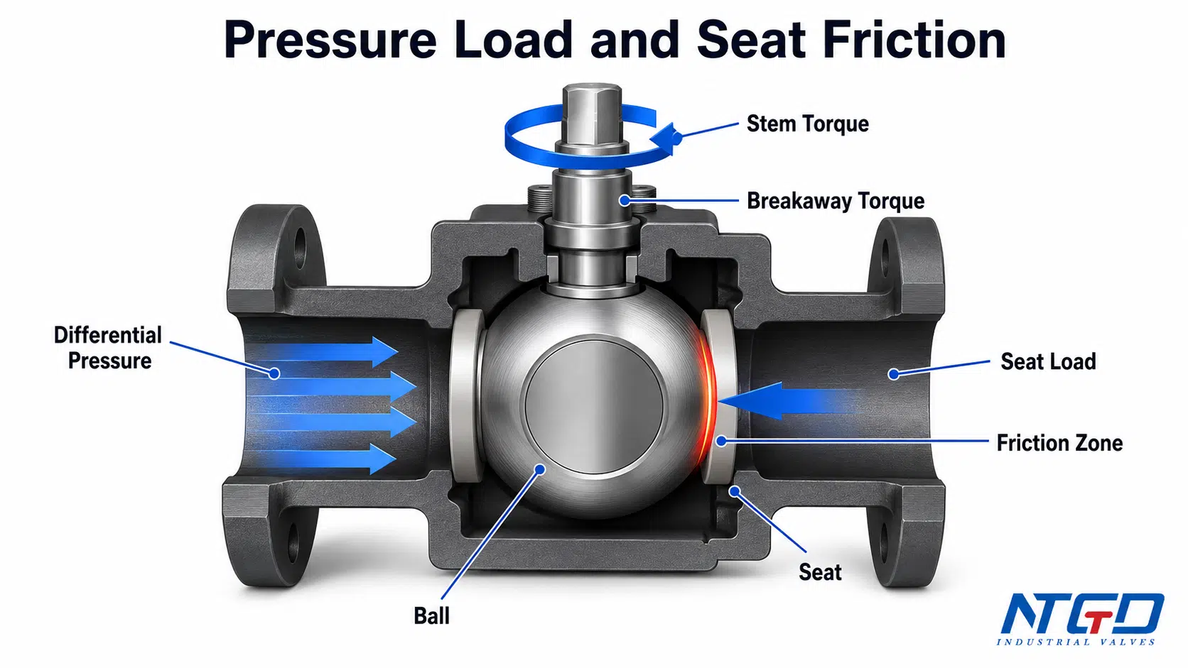
Ball valve torque changes because different resistance forces act on the ball and stem during the operating cycle. The main contributors are seat friction, differential pressure loading, stem packing friction and bearing or trunnion friction.
Ball and Seat Friction
The ball must rotate against the seat contact area. This contact creates friction. The seat material, seat preload, sealing design and surface condition all affect how much torque is required.
Soft seats such as PTFE-based materials may have lower friction in some clean services, but the exact torque still depends on pressure, temperature, seat design and manufacturer construction. Reinforced seats, nylon seats and metal seats can behave differently.
If the seat is damaged, swollen, aged or contaminated by solids, operating torque can increase.
Differential Pressure Loading on the Ball
When the valve is closed and there is pressure difference across the ball, the upstream pressure can push the ball toward the downstream seat. This pressure loading increases contact force at the sealing interface.
In many floating ball valve designs, higher differential pressure can increase seat load and therefore increase breakaway torque. In trunnion mounted designs, the ball is supported by trunnions, but seat loading and sealing design still affect torque.
Le point essentiel est simple : higher pressure can increase torque, but the exact relationship depends on valve design.
Stem Packing, Bearings and Trunnion Friction
Torque is not created only at the ball-seat interface. The stem packing also creates friction around the rotating stem. Bearings, thrust washers, trunnion supports and drive components can add resistance.
In a clean new valve, these friction sources may be predictable. In actual service, packing adjustment, aging, deposits, corrosion or lack of cycling can change the force required to operate the valve.
Why Torque Is Usually Highest at the Start of Movement
The start of movement often requires higher torque because the valve must overcome static friction. The ball and seat have been in contact without movement, and pressure may be loading the sealing surface. This is why breakaway torque is commonly treated as a critical value for actuator selection.
However, this should not be simplified into a universal rule for every valve. Some services, actuator types or valve designs may place different importance on end torque, seating torque or fail-safe operation.
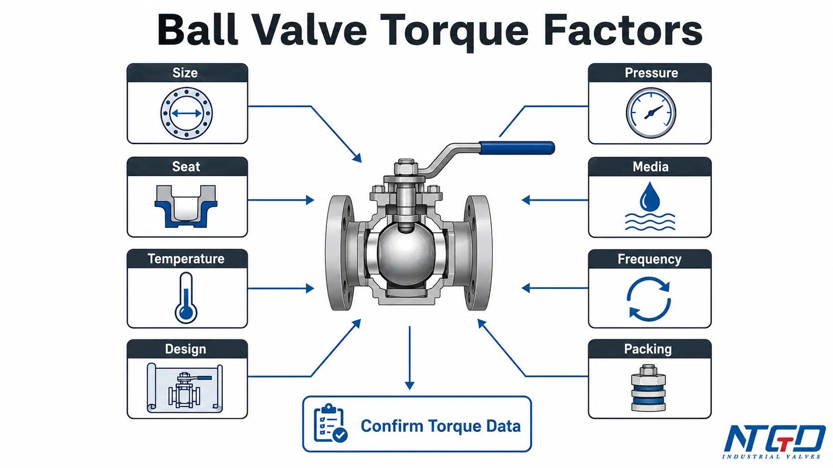
What Affects Ball Valve Torque?
Ball valve torque is affected by valve design and service conditions. Two valves with the same nominal size can require different torque if they use different seats, pressure classes, bore designs or operating conditions.
The following matrix is useful for early screening. It helps identify which design and service factors may change the torque requirement before the manufacturer confirms the exact torque data.
Valve Size, Bore Type and Pressure Class
Valve size is a basic factor, but it should not be used alone. Larger valves usually have larger sealing surfaces and higher contact forces, but torque also depends on seat design, bore type and pressure class.
A full-port ball valve may have a different ball and seat geometry than a reduced-port design. A higher pressure class valve may also have stronger construction and different seat loading behavior.
Seat Material: PTFE, Reinforced Seat, Nylon and Metal Seat
Seat material has a direct effect on friction and sealing force.
Soft seats may provide lower torque in many clean services, while reinforced seats, nylon seats or metal seats may be selected for higher pressure, temperature, abrasive or severe service conditions. These materials can change torque requirements.
Metal seats or reinforced seats may require different contact stress and friction behavior than standard soft seats. This is why seat material should be checked together with seat design, seat preload and manufacturer torque data, not only by material name.
Seat selection should not be made only for low torque. It must also match media, temperature, pressure, shutoff requirement and service life expectations.
Where the main selection question is seat construction rather than torque alone, NTGD’s robinets à boisseau sphérique à siège métallique ou à siège souple guide can help compare the service boundary.
Differential Pressure, Line Pressure and Temperature
Differential pressure across the closed valve can increase the force between the ball and seat. Line pressure, pressure direction and pressure balancing features can all affect torque.
Temperature can also change torque because seat materials and seals respond differently at high or low temperatures. Cold service, high-temperature service and thermal cycling should be reviewed against the valve manufacturer’s data.
For high differential-pressure service, review torque together with pressure class, construction and sealing materials; NTGD’s vanne à bille haute pression guide provides additional selection context.
Media Type: Clean Liquid, Gas, Slurry, Viscous or Dry Service
Media type can strongly affect torque.
Clean lubricating liquids may behave differently from dry gas, slurry, polymerizing fluid, crystallizing media or viscous service. Solids can increase friction or cause buildup. Dry service can reduce lubrication at the contact surfaces. Sticky or scaling media can increase breakaway torque after standstill.
For this reason, torque review should include the actual media, not only valve size and pressure class.
Operation Frequency, Standstill Time and Cycling Duty
A valve operated once per month may behave differently from a valve cycled many times per day. Long standstill periods may increase breakaway torque if seats remain compressed or if media deposits form near the ball and seat.
Frequent cycling can also affect seat wear, packing behavior and actuator selection. For automated service, cycling frequency should be part of the RFQ data.
Floating Ball Valve vs Trunnion Mounted Ball Valve
Floating ball valves and trunnion mounted ball valves do not load the ball in the same way.
In a floating ball design, the ball can move slightly under pressure and load the downstream seat. As differential pressure increases, the ball may press more strongly against the seat, increasing the starting friction that the actuator must overcome.
In a trunnion mounted design, the ball is mechanically supported by trunnions, and the seat design often plays a major role in sealing and torque behavior. Trunnion designs are common in larger sizes and higher pressure services, but the exact torque still depends on manufacturer construction.
Design affects how pressure load is transferred to the ball and seat. For this reason, floating ball valve torque and trunnion ball valve torque should not be interchanged without manufacturer confirmation.
| Facteur | How it may affect torque | Éléments à vérifier avant la sélection |
|---|---|---|
| Taille de la vanne | Larger sealing area generally increases torque demand, but design details still matter | Nominal size, bore type, actual valve design |
| Classe de pression | Higher pressure design may change construction, seat load and breakaway behavior | Pressure class and maximum differential pressure |
| Matériau du siège | Different materials create different friction and compression behavior | PTFE, reinforced seat, nylon, metal seat or special seat |
| Type de média | Solids, dryness, viscosity or deposits can increase actual operating torque | Fluid type, cleanliness, solids, viscosity |
| Température | Seat and seal behavior can change at high or low temperature | Normal, minimum and maximum operating temperature |
| Fréquence de fonctionnement | Cycling and standstill affect breakaway behavior | Manual, occasional, frequent cycling or automated duty |
| Conception des vannes | Floating and trunnion designs transfer pressure load differently | Floating, trunnion mounted, soft seated, metal seated |
| Garniture de tige | Packing friction adds to operating torque | Packing design and service condition |
| État du service | Harsh service may require additional review and margin | Corrosion, scale, slurry, dry gas, polymerizing media |
These factors directly affect actuator output requirements, safety factor and final actuator model selection. Selecting an actuator only by nominal valve size can lead to undersizing, unnecessary oversizing or an actuator package that does not match the real service condition.
Ball Valve Torque Calculation: What Can and Cannot Be Calculated
Ball valve torque calculation is useful during early engineering review, but it should not be treated as a replacement for manufacturer-confirmed torque data.
The reason is that ball valve torque is not determined by one simple geometric formula. It depends on friction, seat design, pressure loading, stem packing, bearing or trunnion resistance, media behavior and temperature.
Why There Is No Universal Ball Valve Torque Formula
A universal ball valve torque formula would require assumptions about the ball-seat contact area, seat friction coefficient, pressure loading, stem packing friction, bearing friction, seat preload and service conditions. These values are not the same across valve manufacturers or valve designs.
This is why two valves with the same nominal size and pressure class may have different torque requirements.
A rough calculation can help estimate whether torque may be low, medium or high for early review, but it should not be used as final actuator sizing data without manufacturer confirmation.
What a Rough Torque Estimate Can Show
A rough torque estimate can help identify:
- whether the valve may require manual operation, gearbox or actuator;
- whether high differential pressure may increase breakaway torque;
- whether severe media or seat material may require a higher service factor;
- whether actuator output should be reviewed more carefully;
- whether a manufacturer torque chart is required before order confirmation.
In practical terms, a rough torque estimate usually considers ball-seat contact load, differential pressure loading, seat friction behavior, stem packing friction and bearing or trunnion resistance. These variables can support early screening, actuator preselection and risk flagging, but they cannot replace confirmed torque data for the exact valve construction and service condition.
A rough estimate is useful for screening. It is not a final guarantee of operating torque.
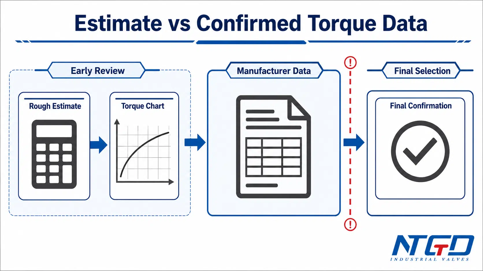
What Must Be Confirmed by the Valve Manufacturer
For final selection, the valve manufacturer should confirm the torque data for the exact valve configuration.
| Objet | Can be estimated during early review? | Must be confirmed for final selection? | Pourquoi c'est important |
|---|---|---|---|
| Valve size and bore | Oui | Oui | Size and bore affect ball and seat geometry |
| Classe de pression | Oui | Oui | Pressure class affects construction and seat load |
| Matériau du siège | Partly | Oui | PTFE, reinforced, nylon and metal seats have different friction behavior, preload and design dependence; manufacturer data is needed for final torque |
| Pression différentielle | Oui | Oui | Higher differential pressure may increase breakaway torque |
| Type de média | Partly | Oui | Solids, dryness, viscosity and deposits affect operation |
| Température | Partly | Oui | Seat and seal behavior changes with temperature |
| Breakaway torque | No reliable universal estimate | Oui | Critical for actuator start capability |
| Running torque | No reliable universal estimate | Oui | Required for movement through stroke |
| End / re-seat torque | No reliable universal estimate | Oui | Important for final seating and shutoff |
| Safety / service factor | En fonction du projet | Oui | Depends on duty, actuator type and project requirements |
| MAST limit | Non | Oui | Prevents overloading the valve stem |
How Breakaway Torque Is Used in Actuator Sizing
Breakaway torque is often one of the key values used in actuator sizing because the actuator must be able to start valve movement from rest. However, actuator selection should not use breakaway torque alone.
A proper review should consider:
- breakaway torque;
- running torque;
- end or seating torque;
- opening and closing direction;
- actuator output curve;
- air supply pressure or electric actuator output;
- spring return or double acting function;
- safety factor or service factor;
- fail-open or fail-close requirement;
- maximum allowable stem torque.
The actuator must provide enough torque where the valve requires it, without applying unsafe torque to the valve stem or drive components.
How to Read a Ball Valve Torque Chart
A ball valve torque chart is a reference document that helps engineers review torque requirements for a specific valve series, size, pressure class, seat material and service condition. It may be presented as a table, graph or datasheet.
A torque chart should be read carefully because it is usually manufacturer- and configuration-specific.
Common Fields in a Ball Valve Torque Chart
A ball valve torque chart may include:
| Chart field | What it usually means | Pourquoi c'est important |
|---|---|---|
| Taille de la vanne | Nominal valve size | Torque generally changes with valve size |
| Classe de pression | Valve pressure rating or class | Higher pressure class may change torque requirement |
| Pression différentielle | Pressure difference across the closed valve | Often a major factor in breakaway torque |
| Matériau du siège | PTFE, reinforced seat, nylon, metal seat or special seat | Seat friction affects torque |
| Conception des vannes | Floating ball or trunnion mounted | Design changes pressure loading and support |
| Torque unit | Nm, in-lb or ft-lb | Unit conversion errors can cause actuator sizing mistakes |
| Torque stage | BTO, RTO, ETO, BTC, RTC, ETC or similar | Different stages require different actuator review |
| Service factor note | Manufacturer or project margin instruction | May affect final actuator torque requirement |
| Temperature note | Reference temperature or service limits | Seat behavior may change with temperature |
| Media note | Clean fluid, dry gas, slurry or other condition | Actual media can change torque |
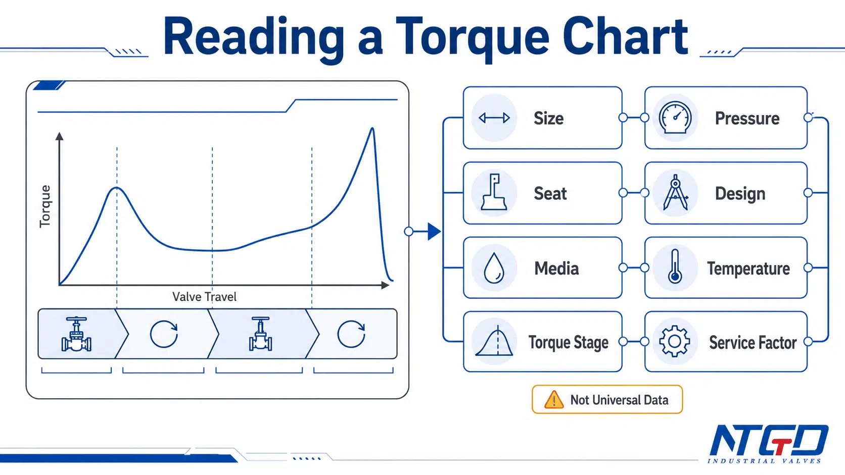
What Torque Charts Usually Show
A torque chart usually shows torque values under defined conditions. These values may be based on valve design, test data, reference pressure, seat material and manufacturer assumptions.
A useful torque chart can help the buyer identify:
- the expected torque range for a given valve size;
- how torque changes with differential pressure;
- whether breakaway torque is higher than running torque;
- whether seat material affects torque;
- whether actuator selection needs additional margin.
What Torque Charts Do Not Show
A torque chart does not always show the full service reality.
| Chart may show | Chart may not show |
|---|---|
| Taille du robinet et classe de pression | Actual media buildup or contamination |
| Matériau du siège | Long standstill effects |
| Differential pressure condition | Corrosion, scale or polymerizing service |
| Reference torque value | Packing adjustment after installation |
| Torque unit | All temperature effects |
| Valve series data | Other manufacturers’ design differences |
| Some torque stages | Full actuator output curve |
| Manufacturer assumptions | Project-specific safety factor |
Ignoring these limitations can result in actuator undersizing, unnecessary oversizing or unreliable operation when the actual service differs from the chart assumptions.
Why Torque Charts Are Manufacturer- and Configuration-Specific
Torque values are closely tied to valve construction. Ball geometry, seat design, seat preload, stem packing, surface finish, bearing structure and trunnion support can all differ between manufacturers.
Even within one manufacturer’s product range, torque can change between:
- floating and trunnion mounted designs;
- full-port and reduced-port valves;
- soft-seated and metal-seated valves;
- low-pressure and high-pressure designs;
- manual and actuated packages;
- standard and severe service constructions.
Torque charts are useful for early comparison, actuator preselection and service range review. Final order confirmation should use torque data for the exact valve configuration and service condition, not a generic series chart or unrelated manufacturer table.
Ball Valve Torque and Actuator Selection Basics
Actuator selection begins with valve torque, but it does not end there. The actuator must be checked against valve torque requirements through the complete opening and closing cycle.
The goal is not simply to choose the largest actuator. The goal is to select an actuator that can operate the valve reliably under service conditions while staying within the valve’s mechanical limits.
Valve Torque Requirement vs Actuator Torque Output
The valve creates a torque requirement. The actuator provides torque output.
For a safe match, compare the required valve torque at each critical point with the actuator’s available torque at the same point in the stroke.
| Selection input | Ce qu'il faut vérifier | Pourquoi c'est important |
|---|---|---|
| Breakaway torque | Torque required to start movement | Actuator must start the valve from rest |
| Running torque | Torque required during rotation | Actuator must continue moving through the stroke |
| End / seating torque | Torque near final position | Actuator must fully open or close the valve |
| Opening / closing direction | Torque may differ by direction | Fail-open and fail-close duties may not be the same |
| Air supply pressure | Pneumatic actuator output depends on supply pressure | Low supply pressure can reduce available torque |
| Spring return function | Spring stroke output may differ from air stroke output | Fail-safe direction must be checked |
| Electric actuator output | Rated torque, control mode and voltage | Prevents stalling or incomplete travel |
| Service factor | Additional margin for duty or service | Helps account for real operating conditions |
| MAST | Maximum allowable stem torque | Prevents actuator from overloading the stem |
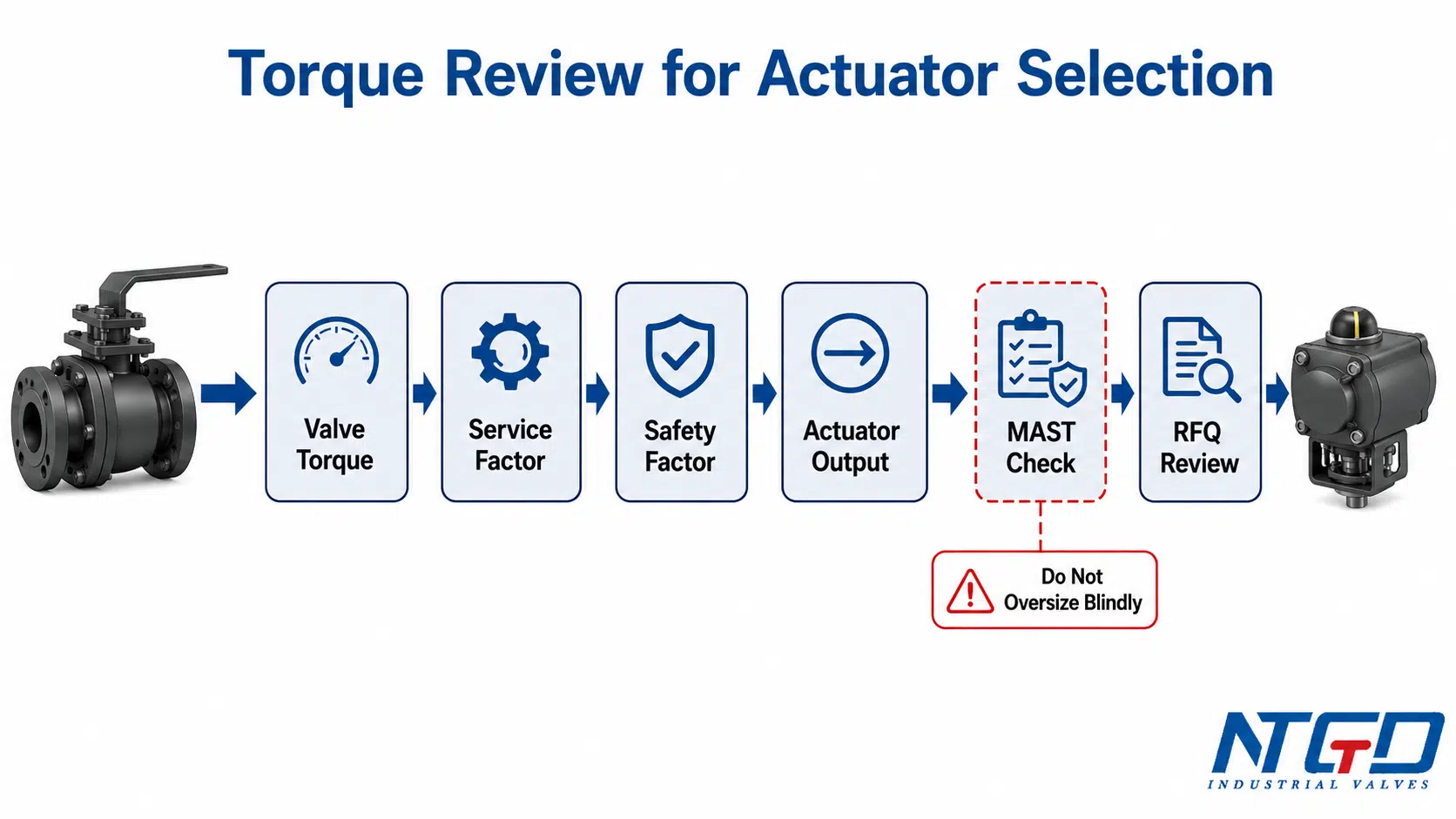
Safety Factor and Service Factor
A safety factor or service factor is often applied because actual service conditions can be more demanding than reference torque data. The factor may account for media effects, temperature, cycling frequency, standstill time or project requirements.
However, a safety factor should not be applied blindly. Too little margin can cause actuator failure or incomplete operation. Too much actuator output may create risk if the actuator can exceed the valve stem or drive train limit.
The correct margin should be reviewed with the valve manufacturer, actuator supplier and project specification.
If reducing actuator size or automation load is a project priority, the separate article on low-torque ball valves for automation systems explains that design direction without replacing the torque confirmation process in this guide.
Spring Return vs Double Acting Pneumatic Actuators
A double acting pneumatic actuator uses air pressure to drive both opening and closing directions. A spring return actuator uses air pressure in one direction and spring force in the fail-safe direction.
This difference matters because actuator output may not be the same in both directions. A spring return actuator must be checked carefully for the fail-safe stroke, especially if the valve requires high breakaway or seating torque.
When selecting a pneumatic actuator, confirm:
- available air supply pressure;
- fail-open or fail-close requirement;
- valve torque in both directions;
- actuator output curve;
- service factor;
- ambient and process conditions.
Electric Actuator Torque and Voltage / Control Requirements
Electric actuator selection should confirm output torque, travel time, duty cycle, voltage, control signal and protection requirements. Torque should be matched to valve demand, but the actuator must also suit the control system and operating frequency.
For electric actuated ball valves, the torque review should include:
- required valve torque;
- actuator rated torque;
- manual override requirement;
- open / close control or modulating control;
- voltage and control signal;
- duty cycle;
- protection de l'environnement ;
- stem torque limit.
If the actuator type is still undecided, compare control logic, response, air supply and site requirements in the electric ball valve vs pneumatic ball valve guide after the valve torque requirement is confirmed.
MAST: Maximum Allowable Stem Torque as a Safety Boundary
MAST means maximum allowable stem torque. It is the torque limit that the valve stem can safely withstand under defined conditions.
MAST is important because actuator selection is not only about having enough torque. The actuator should also avoid applying excessive torque that may damage the stem, drive connection or internal components.
Actuator selection should check both sides of the torque window: actuator output must be sufficient for the required valve torque with service factor, but the selected actuator package or torque-limiting setting should also avoid exceeding the valve’s maximum allowable stem torque.
In high-pressure, automated or severe service applications, MAST should be checked against the actuator output and project specification. This article does not replace a full MAST calculation or standard review; it only highlights MAST as a safety boundary during actuator selection.
For the stem safety boundary, this maximum allowable stem torque review explains why actuator output should be checked against the valve MAST during actuator selection.
Common Ball Valve Torque Selection Mistakes
Torque-related mistakes can lead to incomplete operation, actuator failure, stem overload or unexpected field problems. The three highest-risk mistakes are using a generic torque chart as final data, replacing maximum differential pressure with nominal pressure, and selecting an actuator only by valve size.
| Erreur | Conséquence possible | How to avoid it |
|---|---|---|
| Using a generic torque chart as final data | Actuator may be undersized or oversized | Use manufacturer torque data for the exact valve configuration |
| Ignoring seat material | Torque may be higher than expected | Review the seat material torque factor and confirm the exact seat design with the valve manufacturer |
| Ignoring media conditions | Deposits, dryness or solids may increase torque | Include media type, viscosity, solids and cleanliness in RFQ |
| Sizing only from nominal valve size | Same size valves may have different torque | Use valve design, seat, pressure and service data in the RFQ checklist |
| Ignoring differential pressure | Breakaway torque may be underestimated | Confirm maximum operating differential pressure, not only pressure class |
| Ignoring operation frequency | Long standstill or frequent cycling may change service requirements | Define cycling duty and standstill conditions |
| Treating floating and trunnion designs the same | Torque behavior may be misread | Confirm valve design before actuator sizing |
| Oversizing without checking MAST | Stem or drive components may be overloaded | Compare actuator output with maximum allowable stem torque |
| Ignoring air supply pressure | Pneumatic actuator output may be lower than expected | Confirm minimum available air supply pressure |
| Treating actuator selection as a catalog match | Valve may not operate reliably in real service | Review valve torque, actuator output, service factor and fail-safe action together |
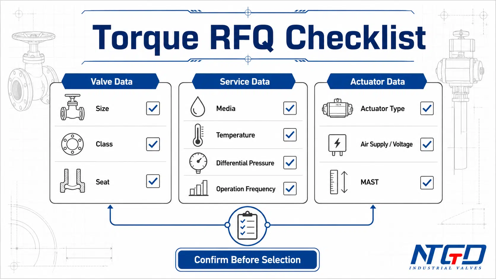
RFQ Checklist for Ball Valve Torque and Actuator Selection
For accurate ball valve torque review and actuator selection, the RFQ should include enough valve, service and actuator data. The more complete the data, the easier it is for the manufacturer to confirm torque and recommend a suitable operating method.
Données de la vanne à confirmer
| Valve data | Pourquoi c'est important |
|---|---|
| Type de vanne | Confirms the request is for a ball valve, not another quarter-turn valve |
| Taille | Basic torque reference |
| Type d'alésage | Full-port or reduced-port geometry can affect torque |
| Classe de pression | Affects construction and pressure loading |
| Matériau du corps | Important for service and design confirmation |
| Matériau du siège | Directly affects friction and torque |
| Soft-seated or metal-seated design | Changes torque behavior and application suitability |
| Floating or trunnion mounted design | Affects pressure loading and support |
| Raccordement final | Helps confirm full valve configuration |
| Stem / mounting interface | Important for actuator or gearbox connection |
Service Data to Confirm
| Service data | Pourquoi c'est important |
|---|---|
| Les médias | Solids, gas, liquid, slurry or viscous service affect torque |
| Température | Seat and seal behavior changes with temperature |
| Normal pressure | Helps confirm service condition |
| Maximum differential pressure | Important for breakaway torque |
| Flow direction / pressure direction | May affect seat loading in some designs |
| Fréquence de fonctionnement | Occasional operation and frequent cycling differ |
| Standstill time | Long stationary periods can increase breakaway torque |
| Clean / dirty service | Deposits or scale can increase torque |
| Corrosive / abrasive service | May require special materials or margins |
Actuator Data to Confirm
| Actuator data | Pourquoi c'est important |
|---|---|
| Manual, gear, pneumatic or electric operation | Determines the operating method |
| Position d'échec | Fail-open, fail-close or fail-in-place affects actuator selection |
| Air supply pressure | Pneumatic actuator output depends on supply |
| Double acting or spring return | Torque output differs by actuator type and direction |
| Voltage / control signal | Required for electric actuator selection |
| Open-close or modulating duty | Affects actuator type and duty cycle |
| Required operation speed | May affect actuator sizing and control |
| Site environment | Ambient temperature, enclosure and protection requirements |
| Safety factor / service factor | Required for project margin |
| MAST / stem torque limit | Prevents over-torque damage |
When the RFQ includes actuator mounting details, the ISO 5211:2026 part-turn actuator attachment standard is a useful reference for interface-related terminology and attachment requirements.
Manufacturer Torque Data and Safety Review
Before confirming an actuated ball valve package, request manufacturer-confirmed torque data for the exact valve configuration. The review should check valve torque requirement, actuator output, service factor, fail-safe direction and MAST boundary together.
A complete RFQ does not need to solve the torque calculation internally. It needs to provide the information required for a correct technical confirmation.
With these data, the manufacturer can confirm valve torque, check actuator matching and review safety boundaries before production or package confirmation.
FAQ About Ball Valve Torque
What is ball valve torque?
Ball valve torque is the rotational force required to turn the ball inside a ball valve. It is used to evaluate manual operation, gearbox selection and actuator selection.
What is breakaway torque in a ball valve?
Breakaway torque is the torque required to start moving the ball from a stationary position. It is often important because the valve must overcome static friction and pressure loading before rotation begins.
What is running torque or run-on torque in a ball valve?
Running torque is the torque required to keep the ball moving after it has started rotating. “Run-on torque” is sometimes used informally to mean running torque, but the exact term should be checked against the manufacturer’s torque data.
Is operating torque the same as breakaway torque?
No. Operating torque is a general term that may include several torque stages. Breakaway torque specifically refers to the torque required to start movement from rest.
How do you calculate ball valve torque?
Ball valve torque can sometimes be roughly estimated during early review by considering seat friction, differential pressure loading, stem packing friction and valve design. However, there is no universal formula that works for every ball valve. Final torque should be confirmed by the valve manufacturer for the exact configuration and service condition.
Can I use one ball valve torque chart for all valves?
No. A ball valve torque chart is usually specific to a manufacturer, valve series, size, pressure class, seat material and service condition. Using a generic torque chart as final actuator sizing data is one of the most common selection mistakes. Final confirmation should use torque data that matches the actual valve configuration.
What torque should be used for actuator sizing?
Actuator sizing should consider the highest relevant required torque point through the operating cycle, including breakaway torque, running torque and end or seating torque. It should also check actuator output curve, service factor, fail-safe direction and maximum allowable stem torque.
Why is a safety factor used for actuator sizing?
A safety factor helps account for real service conditions that may increase torque, such as media deposits, temperature changes, long standstill time, dry service or cycling duty. The factor should be selected carefully so the actuator is not undersized or excessively oversized.
How does seat material affect ball valve torque?
Seat material affects friction, compression and sealing behavior. PTFE, reinforced seats, nylon seats and metal seats can have different torque requirements. The exact effect depends on the valve design and service condition.
Is torque the same for floating and trunnion ball valves?
No. Floating ball valves and trunnion mounted ball valves support and load the ball differently. Their torque behavior can be different, especially under higher differential pressure or larger valve sizes.
What data should I send for ball valve actuator selection?
Send valve size, pressure class, bore type, seat material, body material, media, temperature, normal pressure, maximum differential pressure, operation frequency, actuator type, air supply or voltage, fail position and any project safety factor or MAST requirement.
Conclusion: Confirm Torque Before Selecting the Actuator
Ball valve torque selection should follow three principles: cover the full stroke, connect torque factors to the real service condition, and check both actuator torque margin and stem torque limit.
Ball valve torque is not a single fixed value. It changes through the operating cycle and depends on breakaway torque, running torque, end torque, seat friction, differential pressure, media, temperature, operation frequency and valve design.
A torque chart or rough calculation can support early review, but it should not replace manufacturer-confirmed torque data. For final actuator selection, the valve torque requirement must be compared with actuator output, service factor, fail-safe direction and maximum allowable stem torque.
The safest approach is to treat torque as part of the full valve specification. Confirm the valve design, service data and actuator requirements together before ordering a manual, geared, pneumatic or electric actuated ball valve package.
Soutien aux applications et aux spécifications
NTGD Valve can review ball valve torque and actuator matching as part of specification confirmation. For RFQ review, provide valve size, pressure class, seat material, media, temperature, differential pressure, operating frequency and actuator requirements so the torque requirement and actuator selection basis can be checked before production confirmation.
