Author Name: Bruce Zheng
Author Role: Co-Founder and Valve Engineer at NTGD Valve
Author Bio: Bruce Zheng is Co-Founder and Valve Engineer at NTGD Valve, focusing on industrial valve selection, pressure-control valve applications, and technical content for global B2B buyers.
Last Updated: June 10, 2026
A hydraulic pressure reducing valve is a pressure-control valve used in hydraulic systems to reduce a higher inlet pressure to a lower, controlled downstream pressure. It is commonly used when one branch circuit, actuator, clamp, pilot line, or auxiliary function needs a pressure lower than the main pump supply pressure. If the reduced-pressure branch is selected or adjusted incorrectly, the result can be excessive actuator force, component stress, heat generation, leakage risk, or unstable machine motion.
In hydraulic product searches, a hydraulic pressure reducing valve may also be called a hydraulic pressure regulator or hydraulic pressure regulator valve. These terms can overlap in buyer language, but they should not be treated as fully interchangeable until the circuit function is confirmed. In this article, the focus is specifically on hydraulic oil systems where the valve controls reduced pressure on the downstream side of a circuit.
Water pressure reducing valves, steam PRVs, plumbing regulators, hydronic PRVs, PVC reducers, and fire protection PRVs use different fluids, pressure ranges, materials, installation rules, and selection logic. This guide focuses on hydraulic pressure reducing valves used in industrial hydraulic systems. It explains how they work, how direct-acting and pilot-operated types differ, where they are used, what to check before selection, and how to diagnose common pressure-control problems without turning the page into a full adjustment manual.
What Is a Hydraulic Pressure Reducing Valve?
A hydraulic pressure reducing valve is a valve that maintains a lower pressure in part of a hydraulic system while the main hydraulic circuit remains at a higher pressure. It is normally installed where the pressure required by a branch circuit is lower than the available pump or upstream pressure.
The key point is that the valve controls the downstream pressure, not the entire system pressure. When the downstream pressure is below the set value, the valve allows flow to pass. When the downstream pressure approaches the set value, the valve throttles the flow path so the reduced-pressure branch does not continue rising with the main system pressure.
A hydraulic pressure reducing valve does not create pressure by itself. It controls pressure by restricting flow and responding to downstream pressure feedback. This is why the valve must be selected together with the circuit layout, flow demand, set pressure, drain condition, fluid condition, and installation method.
| Term | Meaning in this article |
|---|---|
| Inlet pressure | The upstream or pump supply pressure entering the valve |
| Reduced pressure | The lower controlled pressure delivered to the downstream branch |
| Downstream side | The branch, actuator, pilot circuit, or secondary circuit after the valve |
| Set pressure | The target pressure value the valve is adjusted or designed to maintain |
For engineering selection, the most important question is not only “what is the valve called?” but “which side of the circuit should this valve control?” A hydraulic pressure reducing valve should be used when the controlled pressure is required downstream of the valve.
What Does a Pressure Reducing Valve Do in a Hydraulic System?
A pressure reducing valve in a hydraulic system creates a lower-pressure zone inside a system that may otherwise operate at a higher main pressure. This is useful when one actuator, tool, clamp, pilot circuit, or auxiliary function should not receive the full pump supply pressure.
For example, a high-pressure main circuit may supply a lower-pressure pilot branch, clamping branch, or auxiliary actuator. If the full system pressure reaches that branch, the result may be excessive force, component stress, seal damage, unstable movement, or unnecessary heat generation.
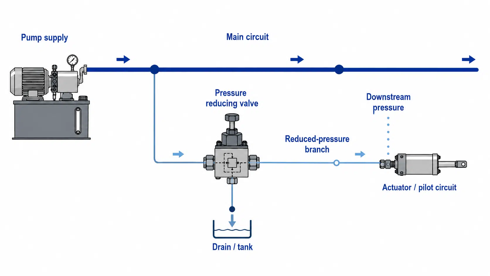
A pressure reducing valve helps prevent that by controlling the downstream branch pressure.
| Circuit area | Pressure condition | Role of the pressure reducing valve |
|---|---|---|
| Pump supply / main line | Higher available system pressure | Supplies pressure to the main circuit |
| Reduced-pressure branch | Lower controlled pressure | Protects components or controls actuator force |
| Downstream sensing side | Monitors outlet pressure | Signals the valve to open, throttle, or stabilize |
| Tank / drain path, if required | Carries pilot or leakage flow | Helps prevent pressure setting errors caused by backpressure |
| Actuator / pilot circuit | Uses controlled pressure | Receives pressure matched to its function, not necessarily full system pressure |
This is why a hydraulic pressure reducing valve is a circuit-level decision, not just a valve-size decision. Selecting the wrong reduced pressure level can directly affect actuator force, system heat, pressure stability, seal life, and downstream component reliability. The buyer or engineer must know which part of the hydraulic system needs reduced pressure and what pressure that branch should maintain under working conditions.
Main Components of a Hydraulic Pressure Reducing Valve
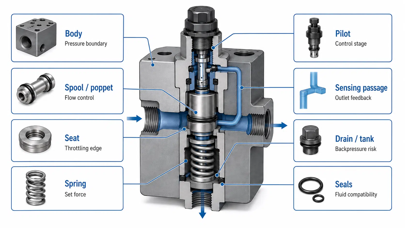
The components of a hydraulic pressure reducing valve vary by design, but most valves include a pressure body, a control element, a spring or pilot mechanism, a downstream sensing path, seals, and sometimes a drain or tank connection.
The purpose of the component section is not only to identify parts. Each component affects pressure control, stability, leakage risk, response, contamination sensitivity, or service suitability.
| Component | Function | Selection / service impact |
|---|---|---|
| Body | Contains pressure and internal flow passages | Must match pressure rating, port type, mounting form, and hydraulic fluid conditions |
| Spool, poppet, or control element | Opens or throttles the flow path | Affects response, stability, contamination sensitivity, and pressure control accuracy |
| Seat or control edge | Creates the controlled restriction | Wear or debris can cause leakage, pressure creep, or poor reduced-pressure control |
| Spring | Provides mechanical setting force | Spring range must match the required reduced pressure range |
| Adjustment screw or knob | Changes the spring compression or pressure setting | Should be locked or protected when the setting must remain stable |
| Pilot valve | Controls the main valve element in pilot-operated designs | Useful for higher flow or more stable reduced pressure, but pilot passages must stay clean |
| Diaphragm, piston, or sensing element | Responds to downstream pressure | Design depends on valve construction, pressure range, and required response |
| Sensing passage | Transfers downstream pressure signal to the control element | Blockage can delay feedback, create incorrect outlet pressure, or cause unstable pressure control |
| Drain / tank port | Routes pilot flow or leakage to tank in some designs | A restricted drain or excessive backpressure can shift the setting and make the reduced pressure unstable |
| Seals and gaskets | Prevent external leakage and separate fluid zones | Must be compatible with hydraulic fluid, temperature, and pressure |
| Strainer or filtration support, internal or external | Helps keep debris away from sensitive control edges and pilot passages | Filtration condition affects valve life, pressure stability, and troubleshooting reliability |
Direct-acting valves usually have a simpler internal structure. Pilot-operated valves add a pilot stage so the main element can handle larger flow or maintain more stable pressure under changing demand. Some reducing-relieving valves also include a path that can relieve excess downstream pressure to tank.
How Does a Hydraulic Pressure Reducing Valve Work?
A hydraulic pressure reducing valve works by sensing downstream pressure and changing the opening of the flow path. Hydraulic pressure reducing valves are normally open when downstream pressure is below the set point, which means they allow flow to pass into the reduced-pressure branch until the branch pressure approaches the target setting.
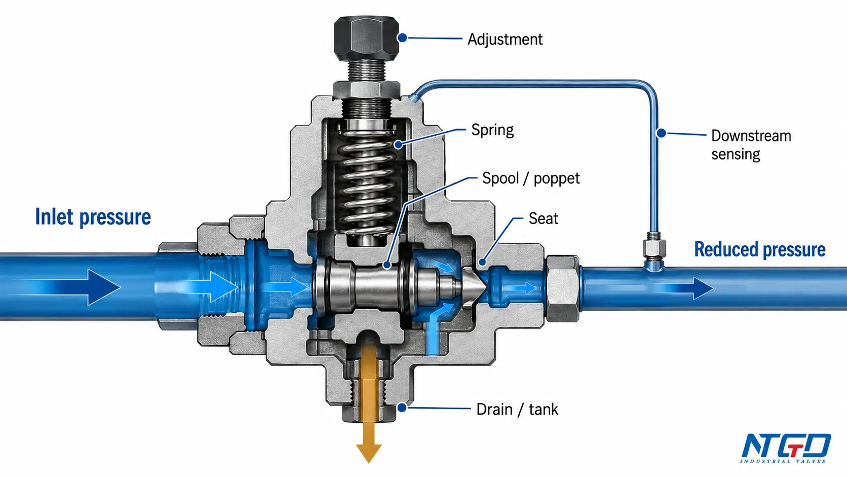
When downstream pressure is lower than the set value, the valve allows flow to pass. When downstream pressure reaches the set value, the valve begins to throttle the inlet flow to maintain the reduced pressure.
The exact internal construction depends on whether the valve is direct-acting, pilot-operated, proportional, cartridge-style, inline, modular, or reducing-relieving. The basic control logic is similar.
Normal Flow Condition
When the downstream pressure is below the set pressure, the spring force keeps the valve open enough for hydraulic fluid to flow into the reduced-pressure branch. The actuator, pilot line, clamp, or auxiliary circuit receives oil from the upstream line.
At this stage, the valve is not acting like a shutoff valve. It is allowing the branch circuit to build pressure toward the desired reduced pressure.
Downstream Pressure Reaches the Set Value
As the downstream branch receives flow, outlet pressure increases. A sensing passage or pilot path communicates this downstream pressure back to the control element.
When downstream pressure approaches the spring setting or pilot setting, the control element starts to move toward a throttling position. This reduces the flow opening and prevents the downstream side from continuing to rise with the full pump supply pressure.
Throttling and Reduced Pressure Control
The valve continuously balances spring force, hydraulic pressure force, and flow demand. If the downstream pressure drops because the actuator or branch circuit consumes flow, the valve opens more. If downstream pressure rises toward the set value, the valve throttles more.
This balancing action is what maintains reduced pressure. It also explains a key engineering boundary: a pressure reducing valve is not a pressure source. It can only maintain reduced pressure when inlet supply is sufficient, the valve has enough flow capacity, and downstream demand stays within the selected valve range.
This sequence is often easiest to understand with a working principle diagram because the relationship between the sensing passage, spool or poppet, spring force, inlet flow, and outlet pressure is visual rather than only textual.
| Step | What happens | Engineering meaning |
|---|---|---|
| 1. Demand begins | The downstream branch needs flow | The valve opens enough to supply the branch |
| 2. Pressure rises | Reduced-side pressure approaches the set value | The sensing passage detects outlet pressure |
| 3. Set pressure is reached | Spring or pilot force is balanced by downstream pressure | The valve begins to throttle |
| 4. Pressure is maintained | Flow opening changes with branch demand | The downstream branch stays near the target pressure |
| 5. Excess downstream pressure occurs | The response depends on valve design | A reducing-relieving valve may route pressure to tank |
Drain or Reducing-Relieving Behavior
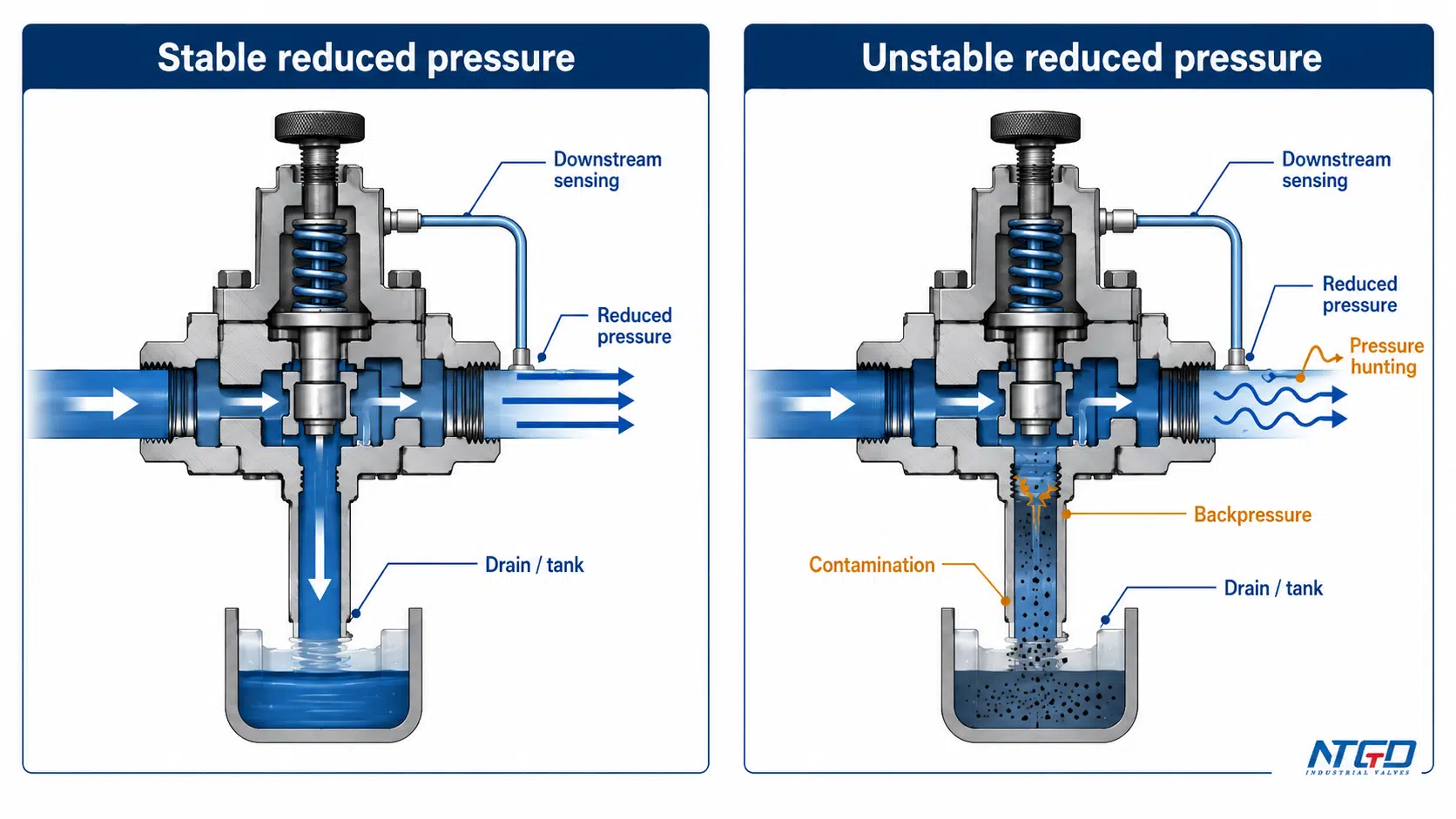
Some hydraulic pressure reducing valves require a drain or tank path for pilot flow or internal leakage. If that drain path is restricted or exposed to excessive backpressure, the reduced pressure may become unstable or higher than expected.
A reducing-relieving valve adds another important function. It can reduce inlet pressure to a set downstream pressure, and it may also relieve excess downstream pressure caused by external force, thermal expansion, or load reaction.
This function must be verified against the specific circuit schematic and valve datasheet rather than assumed from the valve name alone. A standard reducing valve and a reducing-relieving valve may look similar in a product list, but they do not handle excess downstream pressure in the same way.
Types of Hydraulic Pressure Reducing Valves
Hydraulic pressure reducing valves are better classified by control principle and circuit function than by generic body material. The old “plastic hydraulic pressure reducing valve” category is not a reliable core type for this page because plastic and PVC pressure reducers usually belong to plumbing, water, or low-pressure utility systems, not industrial hydraulic oil circuits.
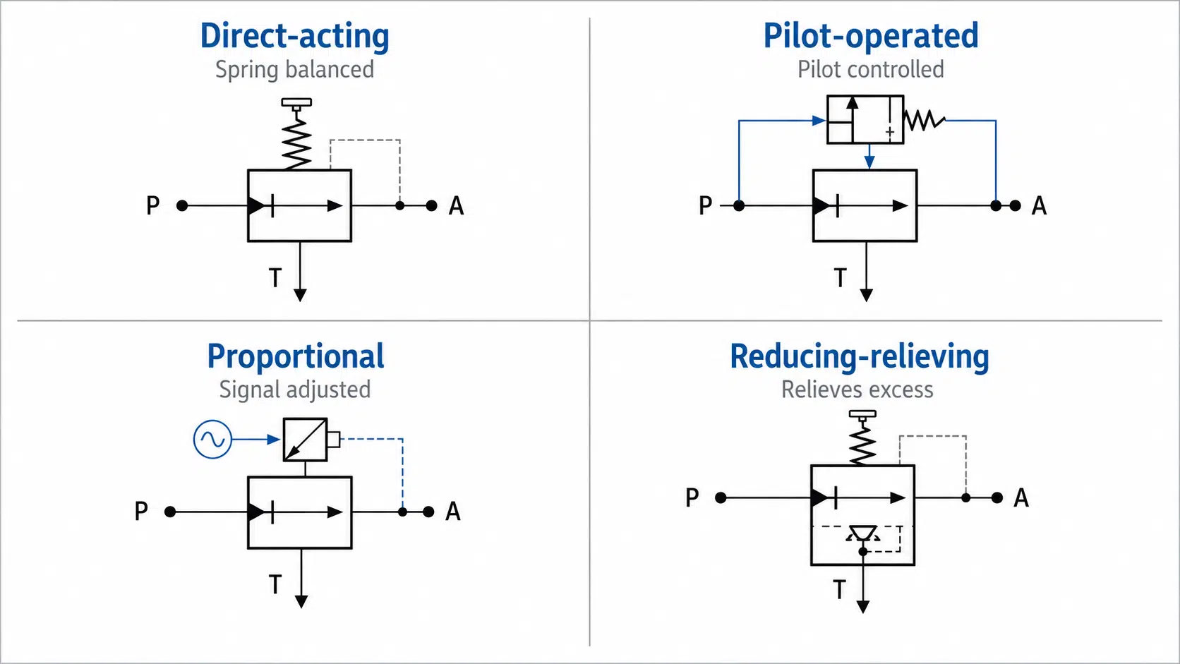
The main hydraulic types are direct-acting, pilot-operated, proportional, and reducing-relieving designs. Mounting forms such as inline, cartridge, sandwich, and modular construction describe installation style, not the basic pressure-control principle.
| Type | How it works | Best fit | Watch point |
|---|---|---|---|
| Direct-acting pressure reducing valve | Downstream pressure acts directly against spring force | Smaller flow, simple branch circuits, compact systems | Confirm that flow and pressure stability needs are within the reliable range of a simple direct-acting design |
| Pilot-operated pressure reducing valve | A pilot stage controls the main valve element | Higher flow, more stable pressure control, larger circuits | Pilot passages, drain condition, and contamination control must be checked during selection |
| Proportional pressure reducing valve | An electrical signal changes the pressure setting | Variable pressure control, automated machines, dynamic pressure changes | Useful for controlled pressure variation, but it should not dominate general mechanical selection discussions |
| Reducing-relieving valve | Reduces pressure and may relieve excess downstream pressure | Circuits affected by external loads, heat, trapped pressure, or reverse force | Must be confirmed from schematic and datasheet before replacement or RFQ |
| Inline / cartridge / sandwich / modular form | Describes installation layout | Piping, manifold, stack, or compact hydraulic block installation | Must match the system layout, porting standard, and available installation space |
Direct-Acting Pressure Reducing Valve
A direct-acting pressure reducing valve uses a spring and control element to respond directly to downstream pressure. It is simple, compact, and often suitable for smaller flow branches where the pressure requirement is not highly dynamic.
Its advantage is simplicity. Its limitation is that it may not provide the same pressure stability as a pilot-operated design under larger flow or rapidly changing load conditions. For final selection, the engineer should confirm that the required flow range and pressure stability are suitable for a direct-acting valve.
Pilot-Operated Pressure Reducing Valve
A pilot-operated pressure reducing valve uses a pilot stage to control a larger main valve element. This structure is often selected where the branch flow is higher or where more stable pressure regulation is needed.
The pilot design can improve control behavior, but it also makes the circuit more sensitive to pilot passage contamination, drain condition, and correct installation. If the valve is used in a dirty hydraulic system or a circuit with drain backpressure, the pilot stage should be checked carefully during selection.
Proportional Pressure Reducing Valve
A proportional pressure reducing valve adjusts the pressure setting according to an electrical command signal. It is used when the required reduced pressure must change during machine operation.
For a general hydraulic pressure reducing valve selection discussion, proportional control should remain a special case. The first selection question is still the required reduced pressure, flow rate, valve type, mounting form, drain condition, and circuit behavior.
Reducing-Relieving Valve
A reducing-relieving valve combines pressure reduction with the ability to relieve excess downstream pressure under certain conditions. This can be important when a downstream actuator is pushed by an external force or when heat expansion raises trapped pressure.
If the downstream circuit is subject to external load, thermal expansion of trapped oil, or reverse force from an actuator, a standard reducing valve may not be enough because it may not relieve excess pressure from the reduced-pressure branch. In those cases, a reducing-relieving function should be considered and confirmed from the schematic before procurement.
This function is not universal. It must be confirmed before procurement, especially when downstream pressure can rise even after inlet flow is reduced.
Hydraulic Pressure Reducing Valve vs Pressure Regulator vs Relief Valve
In hydraulic component searches and broader industrial PRV discussions, a hydraulic pressure reducing valve is often described as a hydraulic pressure regulator or hydraulic pressure regulator valve.
The most important distinction is the pressure side being controlled.
A hydraulic pressure reducing valve controls the downstream or branch pressure. A pressure relief valve usually protects the upstream or system pressure by opening when pressure exceeds a set limit. A pressure control valve is a broad family term that can include reducing valves, relief valves, sequence valves, unloading valves, counterbalance valves, and other pressure-control devices.
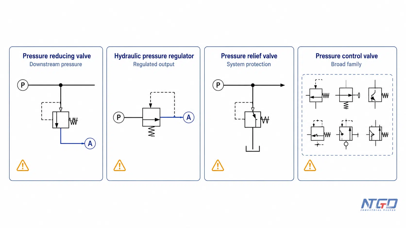
| Term | Main control target | Typical role | Current page treatment |
|---|---|---|---|
| Hydraulic pressure reducing valve | Downstream / branch pressure | Reduces pump supply pressure to a lower controlled pressure | Main topic |
| Hydraulic pressure regulator | Often output / regulated pressure, but usage varies | May overlap with pressure reducing valve or broader regulator products | Supported as secondary wording |
| Hydraulic pressure regulator valve | Alternate commercial or search wording | Often used when buyers search for adjustable hydraulic pressure control | Light support / FAQ |
| Pressure relief valve | Upstream / system pressure | Protects the hydraulic system from overpressure | Boundary only |
| Pressure control valve | Broad valve family | Includes reducing, relief, sequence, unloading, and other valve functions | Boundary only, not the main topic |
Treating a pressure reducing valve, pressure regulator, and pressure relief valve as fully interchangeable without circuit review can lead to incorrect pressure control. A relief valve should not be used as a direct substitute for a pressure reducing valve unless the circuit function has been checked. A pressure reducing valve is intended to create a controlled lower-pressure branch. A relief valve is normally intended to limit maximum pressure.
This article focuses exclusively on downstream pressure reduction. Other pressure control valve types, such as sequence valves, unloading valves, and counterbalance valves, serve different circuit functions and should be evaluated in separate technical guides or product reviews.
Applications of Hydraulic Pressure Reducing Valves
Hydraulic pressure reducing valves are used where one part of a hydraulic system needs lower pressure than the main supply. The most common applications involve pilot circuits, branch actuator circuits, clamping systems, mobile machinery, industrial hydraulic power units, and test systems.
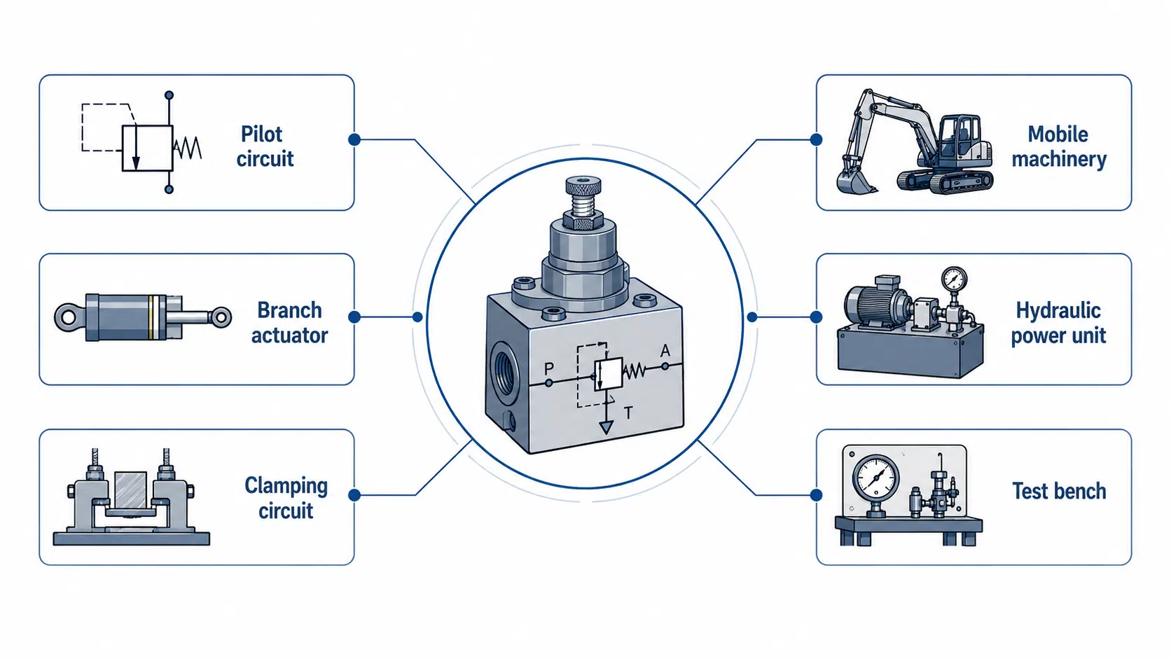
| Application | Why reduced pressure is needed | Selection note |
|---|---|---|
| Pilot circuit | Stable lower pressure is needed for control signals | Confirm pilot pressure and pilot flow before final specification |
| Branch actuator circuit | One actuator needs lower force than the main system can provide | Confirm reduced pressure, load condition, and actuator force requirement |
| Clamping circuit | Excessive clamping force may damage the workpiece or fixture | Check pressure setting and repeatability before final specification |
| Mobile hydraulic machinery | Auxiliary functions may need lower pressure than main lift or drive circuits | Consider vibration, contamination, response, and compact mounting |
| Hydraulic power unit | Different circuits may need different pressure zones | Confirm mounting style, drain requirement, porting, and maintenance access |
| Test bench | Multiple test lines may require different pressure settings | Confirm pressure range, adjustment method, and documentation |
These hydraulic applications are different from water supply, steam pressure reducing valve service, domestic plumbing, irrigation, or fire hydrant pressure reduction.
Using a non-hydraulic pressure reducing valve in a hydraulic oil system may lead to seal incompatibility, unstable pressure control, unsafe selection, or shortened component life. The valve should be selected for hydraulic fluid, hydraulic pressure conditions, and the specific circuit function.
How to Select a Hydraulic Pressure Reducing Valve
As with broader industrial valve selection, selecting a hydraulic pressure reducing valve starts with the circuit requirement, not the valve name.
The most common selection mistake is checking only the set pressure while ignoring flow, drain, installation layout, downstream load behavior, and fluid cleanliness.
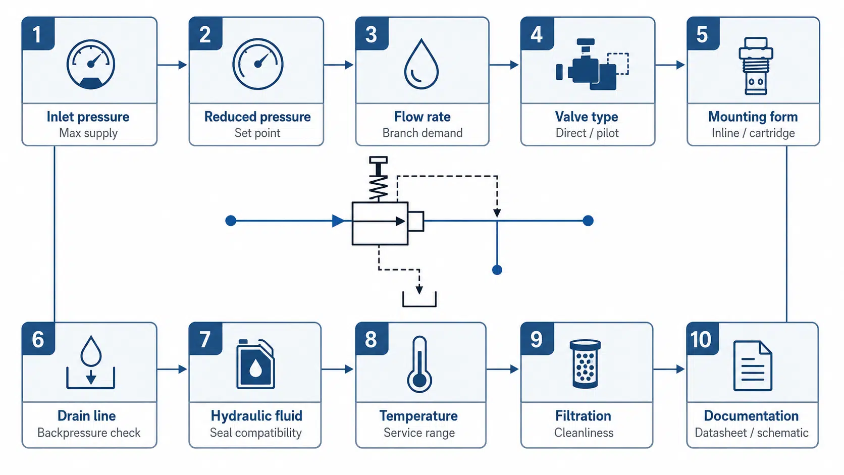
| Selection item | What to confirm | Why it matters |
|---|---|---|
| Maximum inlet pressure | Highest pump or upstream pressure | Confirms body and internal pressure capacity |
| Required reduced pressure | Target downstream set pressure | Determines spring range, pilot range, or control signal |
| Flow rate | Expected branch flow | Prevents excessive pressure drop, heat generation, noise, hunting, or unstable reduced pressure |
| Valve type | Direct-acting, pilot-operated, proportional, or reducing-relieving | Matches control stability, flow demand, and circuit function |
| Mounting form | Inline, cartridge, sandwich, or modular | Must match installation layout, manifold design, and maintenance access |
| Connection / port size | Thread, flange, manifold cavity, or cartridge size | Prevents installation mismatch and flow restriction |
| Drain / tank line | Internal or external drain requirement | Drain restriction or backpressure can shift the setting and cause unstable outlet pressure |
| Adjustment method | Screw, knob, locked setting, sealed setting, or signal-controlled | Affects maintenance, safety, repeatability, and unauthorized adjustment risk |
| Hydraulic fluid | Oil type, viscosity, cleanliness, additive compatibility | Affects seals, spool movement, leakage behavior, and service life |
| Fluid contamination / filtration requirement | System filtration rating and expected fluid cleanliness | Contamination can block sensing passages, damage control edges, and cause pressure instability |
| Temperature | Minimum and maximum operating temperature | Affects seals, leakage, viscosity, response, and pressure stability |
| Documentation | Datasheet, schematic, symbol, GA drawing, or certified drawing | Helps confirm the valve function before procurement or replacement |
For RFQ review, the most useful information is the required reduced pressure, maximum inlet pressure, flow rate, valve type, connection or mounting form, hydraulic oil condition, temperature range, adjustment requirement, drain requirement, and whether a reducing-relieving function is needed.
If the circuit includes external force, drain backpressure, unstable branch demand, contamination concerns, or replacement uncertainty, the RFQ should include schematic and application details for engineering review. Similar-looking hydraulic valves can perform different pressure-control functions, especially in manifold or cartridge systems.
Engineering Value and Limitations
A hydraulic pressure reducing valve helps create different pressure zones inside one hydraulic system. This can protect components, reduce excessive actuator force, stabilize pilot circuits, and improve the control of branch functions.
However, it is not a universal solution for every pressure problem. It does not replace the main system relief valve, and it cannot compensate for poor circuit design, blocked drain lines, severe contamination, incorrect sizing, or wrong installation direction.
| Area | Engineering value | Limitation / caution |
|---|---|---|
| Pressure zoning | Allows one hydraulic system to operate with different pressure levels | Does not replace main system pressure protection |
| Component protection | Reduces pressure reaching sensitive branch components | Wrong setting can still damage downstream equipment |
| Force control | Helps control actuator or clamp force | Load, cylinder size, and mechanical design still matter |
| Stability | Helps maintain reduced pressure under changing demand | Drain condition, flow range, and contamination affect stability |
| Heat and energy | Can prevent unnecessary high pressure in a branch circuit | Throttling generates heat, which can become significant in high-flow or high-pressure-drop applications |
| Maintenance | Pressure readings can guide troubleshooting | Proper readings help isolate whether the issue is the valve, the drain line, contamination, or the circuit load |
The valve should therefore be selected as part of the hydraulic circuit. If the downstream branch has external force, trapped pressure, thermal expansion, or reverse-flow conditions, the designer should confirm whether a standard reducing valve is enough or whether a reducing-relieving design is required.
Troubleshooting and Adjustment Notes
Troubleshooting a hydraulic pressure reducing valve should begin with the symptom, circuit condition, pressure readings, and valve function. A pressure problem is not always caused by the valve itself. It may come from contamination, incorrect setting, blocked sensing passages, drain backpressure, wrong valve type, undersizing, external load, or incorrect installation.
| Symptom | Likely cause | What to check first |
|---|---|---|
| Controlled pressure exceeds set value under normal load | Blocked sensing passage, pilot contamination, wrong setting | Downstream sensing passage, pilot stage, set pressure |
| Pressure rises under light load | Downstream external force, heat expansion, drain restriction | Load condition, reducing-relieving function, drain line |
| Valve does not open | Stuck spool / poppet, insufficient inlet pressure, blocked orifice | Inlet pressure, contamination, control element movement |
| Low delivery pressure | Undersized valve, wrong spring range, blocked inlet | Flow demand, pressure range, strainer or inlet condition |
| Valve does not close or reduce pressure | Seat contamination, wrong installation direction, pilot failure | Seat area, flow direction, pilot control |
| Pressure hunting or unstable reduced pressure, where pressure repeatedly fluctuates above and below the set value | Oversizing, air, contamination, drain backpressure | Sizing, air removal, fluid cleanliness, drain pressure |
| External leakage | Gasket or seal failure, wrong material, overpressure | Seal material, connection condition, pressure and temperature |
Adjustment Safety Boundary
A hydraulic pressure reducing valve may be adjustable, but adjustment should not be the first response to every pressure problem. Before changing the setting, check the actual downstream gauge point, drain restriction, contamination condition, inlet pressure, and current circuit state.
Adjustment should follow the manufacturer’s instructions, system safety procedure, and project documentation. If the valve is adjusted before checking the drain line, sensing passage, oil cleanliness, and downstream load condition, the same pressure problem may return after the setting is changed.
This article is not a full pressure reducing valve adjustment manual. It is intended to help identify what should be checked before adjustment or replacement.
Final Fit-Check Before RFQ
Before requesting a hydraulic pressure reducing valve quotation or replacement review, confirm the following:
| Fit-check item | Confirmed? |
|---|---|
| The valve is intended to control downstream / branch pressure, not main system relief pressure | |
| Maximum inlet pressure is known | |
| Required reduced pressure is known | |
| Expected branch flow rate is known | |
| Direct-acting, pilot-operated, proportional, or reducing-relieving function has been reviewed | |
| Inline, cartridge, sandwich, or modular mounting form has been identified | |
| Port size or manifold cavity requirement is known | |
| Internal or external drain requirement has been checked | |
| Hydraulic oil type, cleanliness, and temperature range are known | |
| Adjustment method and locking requirement are clear | |
| Datasheet, schematic, symbol, or drawing is available for confirmation |
If any of these points are unclear, the valve may still be selectable, but the RFQ should include enough circuit information for an engineering review. For replacement projects, a schematic or existing valve datasheet is especially useful because similar-looking hydraulic valves may perform different pressure-control functions.
FAQ
Is a hydraulic pressure reducing valve the same as a hydraulic pressure regulator?
In many buyer searches, yes, the terms can point to a similar product. A hydraulic pressure reducing valve may be listed or searched as a hydraulic pressure regulator or hydraulic pressure regulator valve. However, they should not be treated as automatically identical in circuit review. The key question is whether the valve controls downstream branch pressure. If the device is being used for a different pressure-control function, the selection may not be the same.
How does a hydraulic pressure reducing valve work?
It senses downstream pressure and changes the opening of the flow path. When downstream pressure is below the set value, the valve opens to supply the branch. When downstream pressure reaches the set value, the valve throttles the inlet flow to maintain reduced pressure.
What does a pressure reducing valve do in a hydraulic system?
It creates a lower-pressure branch inside a hydraulic system. This allows one actuator, pilot line, clamping function, or auxiliary circuit to operate below the main pump supply pressure.
What is the difference between a direct-acting and pilot-operated pressure reducing valve?
A direct-acting pressure reducing valve responds directly to downstream pressure acting against a spring. It is simpler and often used for smaller flow. A pilot-operated pressure reducing valve uses a pilot stage to control the main element and is often selected for larger flow or more stable pressure control.
What is the difference between a pressure reducing valve and a pressure relief valve?
A pressure reducing valve controls downstream or branch pressure. A pressure relief valve usually protects upstream or system pressure by opening when pressure exceeds a set limit. They are different functions. Using a relief valve where a reducing valve is required may leave the branch pressure uncontrolled; using a reducing valve where a relief function is required may leave system protection incomplete.
Can a hydraulic pressure reducing valve be adjusted?
Many hydraulic pressure reducing valves are adjustable, but adjustment should be done only after the circuit condition is checked. Before changing the setting, confirm the downstream pressure gauge point, drain condition, oil cleanliness, inlet pressure, and load state. If contamination, drain restriction, or wrong valve sizing is the real cause, adjusting the screw may not solve the pressure problem.
What does hydraulic PRV valve mean?
In this article, hydraulic PRV means hydraulic pressure reducing valve. In some industries or documents, PRV can also mean pressure relief valve. Always confirm the meaning from the hydraulic schematic, datasheet, and circuit function.
Does a hydraulic pressure reducing valve need a drain line?
Some designs require an internal or external drain path, especially pilot-operated or reducing-relieving valves. The drain requirement depends on valve construction. If a required drain path is restricted or exposed to backpressure, the reduced pressure may become unstable or higher than expected.
What does a hydraulic pressure reducing valve symbol show?
A hydraulic pressure reducing valve symbol usually helps identify a pressure-control function and the controlled side of the circuit. In many schematics, the useful clue is the downstream or outlet-side sensing signal, because a reducing valve controls reduced pressure after the valve. Symbol details should still be checked against the project schematic and manufacturer documentation. A full symbol guide is a separate topic and should not replace valve datasheet review.
What information should I provide for RFQ?
Useful RFQ information includes maximum inlet pressure, required reduced pressure, flow rate, hydraulic fluid, temperature range, valve type, mounting form, port or cavity size, drain requirement, adjustment method, contamination condition, and any available schematic or datasheet.
Conclusion
A hydraulic pressure reducing valve is used when one part of a hydraulic system needs controlled pressure lower than the main pump supply. Its function is not to manage the whole hydraulic system, but to create a specific pressure condition for a specific circuit demand. The key engineering point is downstream pressure control. The valve must be selected by circuit function, not only by name.
For a reliable selection, confirm the reduced pressure, maximum inlet pressure, flow rate, valve type, mounting form, drain condition, hydraulic fluid, contamination condition, temperature range, and documentation. Direct-acting, pilot-operated, proportional, and reducing-relieving valves can all serve different needs, but they are not interchangeable without checking the circuit.
A well-selected hydraulic pressure reducing valve helps protect branch components, control actuator force, stabilize pilot circuits, and improve system behavior. A poorly selected or incorrectly adjusted valve can cause unstable pressure, heat, leakage, or wrong machine function.
If you are selecting or replacing a hydraulic pressure reducing valve, prepare the inlet pressure, required reduced pressure, flow rate, mounting form, hydraulic fluid, temperature range, contamination condition, drain requirement, and schematic information before RFQ. For replacement projects, providing the existing valve datasheet or hydraulic schematic can significantly speed up selection review by confirming the exact valve function, mounting form, and pressure-control requirement. NTGD Valve can help review the application conditions and confirm the valve type, pressure range, connection, and documentation requirements before production.
