Имя автора: Брюс Чжэн
Роль автора: Соучредитель и инженер по клапанам в NTGD Valve
Био автора: Брюс Чжэн - соучредитель и инженер по клапанам в компании NTGD Valve, специализирующейся на выборе промышленных клапанов, их применении и техническом контенте для глобальных покупателей B2B.
Последнее обновление: 23 июня 2026 года
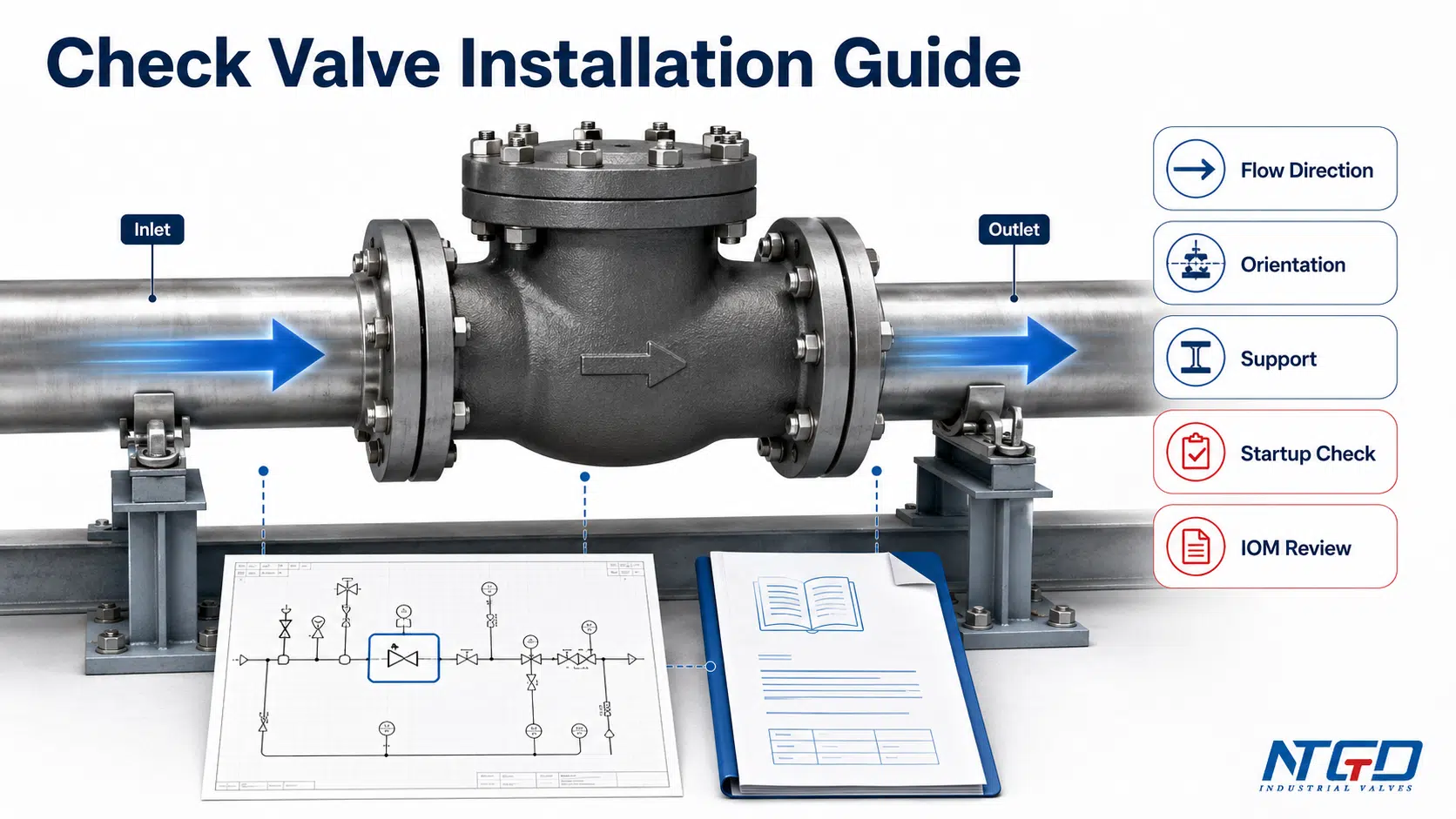
Правильный монтаж обратного клапана — это не просто установка клапана в трубопровод. При монтаже промышленных трубопроводов монтажник должен проверить направление потока, ориентацию клапана, положение установки, состояние прямых участков трубопровода, крепление труб, а также поведение клапана при запуске, прежде чем клапан будет принят в эксплуатацию.
Обратный клапан предназначен для обеспечения потока в одном направлении и предотвращения обратного потока. Если он установлен в обратном направлении, расположен слишком близко к участку турбулентного потока, смонтирован в неправильной ориентации или вставлен в трубопровод с несоосностью, это может привести к утечке, вибрации, ударам, преждевременному износу, нестабильной работе насоса или невозможности закрытия при возникновении обратного потока.
Данное руководство по монтажу обратных клапанов посвящено промышленным трубопроводам, нагнетательным линиям насосов, технологическим системам и проверке инженерных монтажных работ. Оно не касается работ с дренажными насосами в жилых помещениях, трубопроводов для бассейнов, трубок для аквариумов, небольших соединений из ПВХ, склеенных клеем, а также самостоятельного монтажа латунных фитингов.
Краткий ответ: Как следует устанавливать обратный клапан?
В промышленных трубопроводах, на напорных линиях насосов и в технологических системах обратный клапан следует устанавливать таким образом, чтобы стрелка на его корпусе соответствовала направлению потока, его ориентация соответствовала конкретной конструкции клапана, а его расположение исключало нестабильность потока и напряжения в трубопроводе.
Одним словом, правильный монтаж обратного клапана осуществляется непосредственно на объекте только после завершения инженерных проверок: направление потока, ориентация, конструкция клапана, расстояния между элементами, крепление и поведение при запуске должны полностью соответствовать комплекту чертежей, руководству по эксплуатации клапана и техническим условиям проекта.
Перед установкой убедитесь в этом:
| Проверить предмет | Что нужно проверить | Почему это важно |
|---|---|---|
| Направление потока | Стрелка на корпусе, вход/выход, направление потока на схеме P&ID, направление потока в трубопроводе | Обратный клапан может не открываться или не закрываться должным образом. |
| Ориентация | Горизонтальный, вертикальный с восходящим потоком или вертикальный с нисходящим потоком | Принцип действия некоторых конструкций обратных клапанов основан на силе тяжести, положении шарнира, усилии пружины или движении диска. |
| Конструкция клапана | качающийся, подъемный, поршневой, пластинчатый, двухдисковый, пружинный, бесшумный, осевой | Различные конструкции имеют разные ограничения по установке. |
| Расположение насоса / трубопровода | Расстояние от насосов, колен, тройников, переходников и регулирующих клапанов | Турбулентность может привести к вибрации, ударам, износу дисков или нестабильному закрытию. |
| Поддержка и согласование | Опора трубы, выравнивание фланцев, вес клапана, отсутствие принудительной сборки | Клапан не должен воспринимать нагрузку от трубопровода или использоваться для выравнивания трубопровода. |
| Поведение при запуске | Утечка, обратный поток, вибрация, шум, дребезжание, хлопанье | Установка считается завершённой только после того, как клапан начнёт работать надлежащим образом при запуске. |
Для многих промышленных проектов самое надежное правило очень простое: устанавливать клапан следует только после того, как направление, ориентация, расстояние между элементами, крепление и проверки при вводе в эксплуатацию будут подтверждены техническим паспортом клапана, проектной спецификацией и инструкциями производителя по монтажу. Обратный клапан, установленный без такой перекрестной проверки, может пройти визуальный осмотр, но при этом во время запуска все равно демонстрировать вибрацию, обратный поток, удары, риск гидравлического удара или преждевременный износ.
Что означает правильная установка обратного клапана в промышленных трубопроводах
Правильная установка обратного клапана подразумевает, что клапан смонтирован таким образом, чтобы его внутренний запорный элемент открывался при прямом потоке и надежно закрывался при начале обратного потока. Для этого недостаточно просто подобрать размер трубы и номинальную нагрузку фланца.
При монтаже на промышленной линии необходимо проверить четыре отдельных момента:
- Направление потока — В каком направлении средство должно проходить через клапан.
- Ориентация — Независимо от того, установлен ли корпус клапана на горизонтальном трубопроводе, вертикальном трубопроводе с восходящим потоком, вертикальном трубопроводе с нисходящим потоком или наклонном трубопроводе.
- Положение установки — Расположение клапана по отношению к насосам, коленям, переходникам, тройникам, регулирующим клапанам, сетчатым фильтрам и местам доступа для технического обслуживания.
- Техническое состояние — Убедитесь, что клапан закреплён, выровнен, чист и на него не действуют напряжения от трубопровода.
В ходе обсуждений простых монтажных вопросов эти аспекты часто смешивают, однако они не являются одним и тем же. Направление потока определяется тем, совпадает ли стрелка на корпусе с указанием на схеме P&ID и фактическим направлением потока в трубопроводе. Ориентация определяет, допускает ли конструкция запорного устройства горизонтальное подключение, вертикальный восходящий поток или вертикальный нисходящий поток. Положение при монтаже определяет, не находится ли клапан слишком близко к нагнетанию насоса, колену, тройнику или переходнику. Механическое состояние определяет, выровнен ли клапан, чист ли он и закреплен ли он таким образом, чтобы на корпус не действовали напряжения.
Клапан может быть обращен в правильном направлении потока, но при этом установлен в неподходящем вертикальном положении. Клапан может быть правильно ориентирован, но при этом находиться слишком близко к нагнетательному патрубку насоса или колену. Клапан может быть правильно установлен, но при этом выйти из строя преждевременно, если труба смещена или диск загрязнен мусором во время монтажа.
Установка — это не только выбор направления клапана
Стрелка на корпусе указывает монтажнику необходимое направление потока через клапан. Однако это не означает, что монтаж выполнен правильно.
Например, у поворотного обратного клапана направление потока может быть правильным, но все равно необходимо проверить положение шарнирного штифта и движение диска. Поршневой или подъемный обратный клапан может требовать определённого положения корпуса для правильного возврата подвижного элемента. Пружинный или осевой обратный клапан может допускать большую гибкость в выборе ориентации, но точные ограничения всё равно зависят от его конструкции и инструкции по эксплуатации (IOM).
Таким образом, правильная установка обратного клапана представляет собой совокупность таких факторов, как направление потока, конструкция клапана, схема прокладки трубопроводов и проверка при вводе в эксплуатацию. Если направление потока выбрано правильно, но ориентация клапана неверна, запорный элемент может не возвращаться в седло надежно; в этом случае все равно могут возникнуть задержка закрытия, износ диска, обратная утечка или нестабильная работа.
Что не рассматривается в данном руководстве
Данное руководство предназначено для промышленных трубопроводов и технологических систем. В нём не приводятся инструкции по сантехнике в жилых помещениях, касающиеся дренажных насосов, бассейнов, аквариумов, систем полива, водонагревателей, небольших латунных обратных клапанов или соединений из ПВХ, склеенных клеем.
Кроме того, данное руководство не заменяет руководство по эксплуатации производителя, проектную спецификацию трубопроводов или правила техники безопасности на объекте. При окончательном монтаже всегда следуйте утвержденной проектной документации и инструкциям производителя клапана.
Контрольный список перед установкой обратного клапана
Перед установкой обратного клапана убедитесь, что клапан и трубопровод готовы к монтажу. Наибольшее внимание следует уделить проверке направления потока, ориентации клапана и его типу, поскольку именно эти факторы с наибольшей вероятностью могут повлиять на работу клапана в закрытом состоянии. Многие проблемы с обратными клапанами возникают еще до того, как клапан будет закреплен болтами: неправильный тип клапана, неправильная ориентация, мусор в трубопроводе, поврежденные посадочные поверхности, отсутствующие прокладки, неправильное выравнивание труб или неясное направление потока.
| Пункт, подлежащий выполнению до начала монтажа | Что проверить | Почему это важно |
|---|---|---|
| Тип клапана | качающийся, подъемный, поршневой, пластинчатый, двухдисковый, бесшумный, осевой, пружинный | Ориентация и особенности закрытия зависят от конструкции. |
| Размер и класс давления | Соответствие техническим условиям проекта, номинальной нагрузке фланца, классу толщины стенки трубы и эксплуатационным требованиям | Несоответствующий клапан может привести к утечке, затруднениям при монтаже или снижению эксплуатационных характеристик. |
| Материал и отделка | Совместимость корпуса, сиденья, диска, пружины, шарнира, штифта и прокладки | Рабочая среда, температура, коррозия, эрозия и твердые частицы могут повлиять на надежность и срок службы уплотнения. |
| Стрелка потока | Стрелка на корпусе, обозначение входа/выхода, направление чертежа | Обратный клапан может перекрыть поток или не предотвратить обратный поток. |
| IOM / техническое описание | Ограничения, установленные производителем, и требования к монтажу | Некоторые конструкции нельзя устанавливать в любом положении. |
| Состояние труб | Концы труб должны быть чистыми, без сварочного шлака, накипи, камней и рыхлого мусора | Инородные предметы могут повредить сиденье или помешать его закрытию. |
| Прокладки и крепеж | Правильный тип прокладки, длина болтов, схема затяжки, класс фланца | Ненадежная герметизация может привести к внешней утечке или напряжению в фланце. |
| Проверка работы клапана перед монтажом | Закрывающий элемент движется свободно, видимых повреждений нет | Застрявший диск или поврежденная пружина могут выйти из строя при запуске. |
| Трубная опора | Опоры вблизи массивных клапанов и прилегающих трубопроводов | Клапан не должен выдерживать вес трубы, не опирающейся на опоры. |
| Доступ для технического обслуживания | Доступ для осмотра, демонтажа, подъема и последующего технического обслуживания | Правильно установленное оборудование должно оставаться пригодным к эксплуатации. |
Уточните тип, размер, класс и условия эксплуатации клапана
Перед началом монтажа необходимо убедиться, что тип клапана соответствует условиям эксплуатации. Обратные клапаны, предназначенные для работы с чистой жидкостью, шламом, газом, паровым конденсатом или на выходе из насоса, могут иметь разные конструкции запорных элементов.
Подтвердите хотя бы:
- размер клапана;
- класс давления;
- конечное соединение;
- материал корпуса и отделки;
- Материал сиденья;
- рабочая температура;
- направление потока;
- нормальная скорость потока;
- ожидаемое противодавление;
- независимо от того, находится ли клапан рядом с насосом, коленчатым патрубком, переходником, тройником или регулирующим клапаном;
- требуется ли вертикальный монтаж.
Данный этап не является полным руководством по подбору клапанов. Это проверка готовности к монтажу. Если тип клапана не соответствует условиям эксплуатации трубопровода, даже правильный монтаж не сможет компенсировать неверный выбор клапана. Рабочая среда, температура, вероятность коррозии или эрозии, содержание твердых частиц, а также конструкция седла и внутренних деталей также могут повлиять на надежность закрытия и допустимую ориентацию, особенно при вертикальной установке или при низком расходе.
Проверьте концы труб, прокладки, крепеж и чистоту
Перед установкой обратного клапана трубопровод должен быть очищен и выровнен. Остатки сварки, накипь, упаковочный материал, защитные колпачки фланцев или свободные частицы могут повредить седло или заблокировать диск в открытом положении. Концы труб следует подготовить в соответствии с типом соединения и процедурой, предусмотренной проектом.
Для клапанов с фланцевым соединением необходимо проверить состояние прокладки, состояние поверхности фланца, совместимость болтов и последовательность их затяжки. Для клапанов «вафельного» или «ушкового» типа следует убедиться, что клапан правильно отцентрирован между фланцами и что диск или пластины имеют достаточный зазор для перемещения. При сварных или резьбовых монтажах ознакомьтесь с инструкциями производителя, прежде чем применять тепло, крутящий момент или герметик вблизи корпуса клапана.
Проверка направления потока: стрелка на корпусе, схема и линия потока
Обратный клапан является однонаправленным. Первая проверка при монтаже заключается в том, чтобы убедиться, что клапан установлен в правильном направлении потока.
Стрелка на корпусе клапана должна указывать от входа к выходу в соответствии с предусмотренным направлением нормального потока. Монтажник должен сверить стрелку на корпусе клапана с данными схемы P&ID, изометрического чертежа трубопровода, бирки клапана, стрелки на трубопроводе и руководства по эксплуатации проекта. Если эти данные не совпадают, необходимо приостановить работу и уточнить порядок монтажа, прежде чем затягивать клапан в трубопроводе.
| Проверка направления потока | Что сравнивать | Риск в случае пропуска |
|---|---|---|
| Стрелка корпуса клапана | Направление стрелки противоположно обычному ходу технологического процесса | Клапан может быть установлен в обратном направлении. |
| Маркировка входа / выхода | Концы клапана расположены против направления потока в трубопроводе | Закрывающий элемент может не открываться должным образом. |
| P&ID / изометрические чертежи | Нанесение стрелки направления потока вразрез с фактической линией участка | Установка на объекте может противоречить замыслу проекта. |
| Метка клапана / номер строки | Клапан установлен не на назначенной линии | Неправильный клапан может быть установлен в несоответствующей системе. |
| Производитель IOM | Ограничения по направлению и ориентации | Внутренний механизм может не закрываться так, как предусмотрено конструкцией. |
| Наблюдение за стартапом | Прямой поток, закрытие, шум, утечка | Неправильное направление может проявиться только во время работы. |
Стрелка на корпусе и подтверждение входа/выхода
На корпусе большинства промышленных обратных клапанов имеется стрелка, обозначающая направление потока, которая может быть отлита, выштампована или нанесена. Эта стрелка должна соответствовать предусмотренному направлению потока. Если стрелка стала незаметной после нанесения покрытия, утепления или в результате транспортировки, воспользуйтесь утвержденным чертежом и информацией производителя, чтобы определить правильные вход и выход.
Даже если внешняя форма корпуса выглядит практически симметричной, внутренние элементы — седло, диск, пружина, шарнир, поршень, пластина или канал прохождения потока — всё же могут иметь определённую ориентацию. Поэтому окончательная проверка ориентации должна основываться на стрелке, указанной на корпусе, утверждённом чертеже и инструкции по эксплуатации производителя, а не только на внешнем виде.
Перекрестная проверка схем P&ID, маркировки клапанов и руководства по эксплуатации (IOM)
При монтаже в рамках проекта клапан необходимо проверить на соответствие комплекту чертежей до начала монтажа и повторно перед вводом в эксплуатацию. На технологической схеме (P&ID) могут быть указаны направление потока и функция клапана. На изометрической схеме трубопроводов могут быть указаны номер линии, маркировка клапана, ориентация, тип соединения и расположение. В руководстве по эксплуатации (IOM) производителя могут быть определены монтажное положение, точки подъема, момент затяжки болтов, допустимая ориентация или проверки при вводе в эксплуатацию.
Если направление чертежа, стрелка корпуса и ориентация при монтаже не совпадают, эту проблему необходимо устранить до ввода клапана в эксплуатацию.
Для подробного расшифровки стрелок, определения входных и выходных отверстий, а также признаков неправильной установки воспользуйтесь отдельным Руководство по направлению потока в обратном клапане; в данной статье направление потока рассматривается как один из обязательных пунктов проверки при монтаже, а не как полная замена раздела, посвященного этой теме.
Ориентация обратного клапана: горизонтальная, вертикальная с потоком вверх и вертикальная с потоком вниз
Ориентация обратного клапана зависит от его конструкции. Некоторые модели хорошо работают в горизонтальных трубопроводах. Некоторые можно устанавливать в вертикальных трубопроводах с восходящим потоком. Для некоторых требуется специальное подтверждение возможности установки в вертикальных трубопроводах с нисходящим потоком. При промышленном монтаже не следует исходить из того, что все обратные клапаны можно устанавливать в любом направлении.
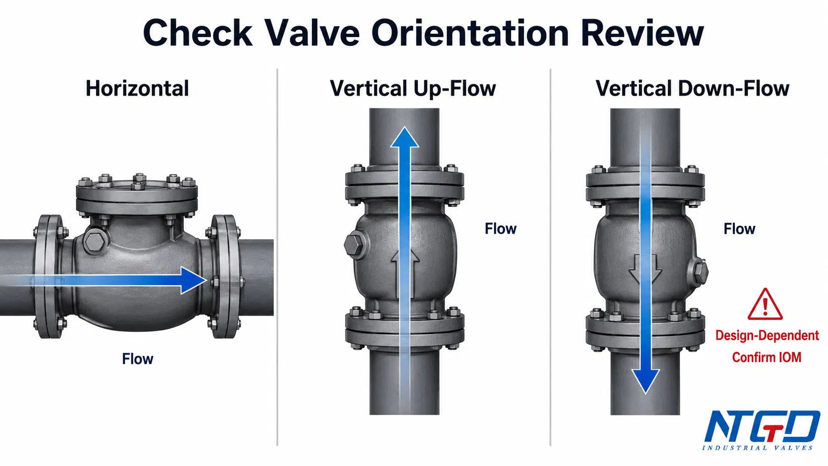
| Ориентация | Общая схема монтажа | Ключевой момент обзора |
|---|---|---|
| Горизонтальная линия | Характерно для многих конструкций типа «свинг», «лифт», «поршневых», «пластинчатых» и «двухдисковых» | Убедитесь в движении диска, шарнира, поршня или пластины. |
| Вертикальный восходящий поток | Возможно в некоторых конструкциях, когда поток поднимает запорный элемент, а обратный поток способствует его закрытию | Уточните тип клапана, наличие пружинного усиления, давление открытия и IOM. |
| Вертикальный нисходящий поток | Более чувствительны, поскольку в некоторых конструкциях сила тяжести может препятствовать закрытию | Используйте только в тех случаях, когда это прямо разрешено конструкцией и производителем. |
| Наклонная линия | С учетом особенностей дизайна | Убедитесь, что элемент закрытия может надежно вернуться в исходное положение. |
Горизонтальный монтаж
Горизонтальный монтаж широко применяется во многих промышленных системах с обратными клапанами, однако он по-прежнему требует проверки конструкции. К поворотным, подъемным, поршневым, двухдисковым вставным или бесшумным обратным клапанам могут предъявляться различные требования в отношении положения шарнира, ориентации крышки, движения диска, пружинного возврата или нагрузки на седло.
При монтаже горизонтального обратного клапана убедитесь, что:
- стрелка на корпусе клапана указывает направление потока;
- элемент закрытия может свободно перемещаться;
- ориентация шарнира или крышки соответствует требованиям IOM;
- клапан не устанавливается сразу после участка с сильной турбулентностью, если это не предусмотрено проектом;
- корпус клапана при необходимости фиксируется;
- Фланцы выравниваются без принудительной установки клапана на место.
Установка с вертикальным восходящим потоком
Для некоторых конструкций обратных клапанов допустима вертикальная установка с восходящим потоком. При такой ориентации нормальный поток проходит через клапан вверх. В зависимости от конструкции восходящий поток может приподнимать диск, поршень, пластину или пружинный запорный элемент, в то время как обратный поток, а также действие пружины или силы тяжести способствуют закрытию клапана.
Однако вертикальный монтаж — это не только вопрос ориентации трубопровода. Это вопрос конструкции клапана. Перед монтажом необходимо убедиться, что клапан подходит для вертикальной установки с восходящим потоком.
Важные проверки включают:
- Допускает ли руководство по эксплуатации клапана вертикальный восходящий поток?
- Надежно ли срабатывает запорный элемент при низком расходе?
- Есть ли там механизм с пружинным приводом?
- Подходит ли давление разрыва для данной области применения?
- Могут ли посторонние частицы оседать рядом с сиденьем или запорным элементом?
- Доступен ли клапан для осмотра?
Установка с вертикальным нисходящим потоком
Вертикальный нисходящий поток является более чувствительным, и его не следует считать приемлемым. При работе в режиме нисходящего потока нормальный поток движется вниз через клапан. В зависимости от конструкции клапана сила тяжести может не способствовать его закрытию, и запорный элемент может не вернуться на седло, как предполагается.
Использовать вертикальную установку с нисходящим потоком следует только в том случае, если в руководстве по эксплуатации, техническом паспорте или проектной документации производителя подтверждается, что данная конструкция клапана подходит для таких условий. Если вертикальной установки с нисходящим потоком избежать невозможно, в рамках проекта необходимо тщательно проанализировать конструкцию клапана, усилие пружины, скорость закрытия, состояние рабочей среды и поведение клапана при запуске.
При неправильной установке с вертикальным нисходящим потоком запорный элемент может возвращаться медленно или не устанавливаться в седло надежно. Во время отключения или остановки насоса это может привести к увеличению продолжительности обратного потока и повысить риск удара, гидравлического удара или ускоренного износа седла.
Матрица конструкций клапанов: какие типы обратных клапанов требуют особого внимания при выборе ориентации?
Различные типы обратных клапанов имеют разные ограничения по монтажу. Воспользуйтесь приведенной ниже таблицей, чтобы быстро определить, какие конструкции требуют наиболее тщательной проверки ориентации до окончательного утверждения схемы трубопроводов. В ней показано, как сила тяжести, положение шарнира, направляемое перемещение, пружинный привод и направление потока могут повлиять на монтаж обратного клапана.
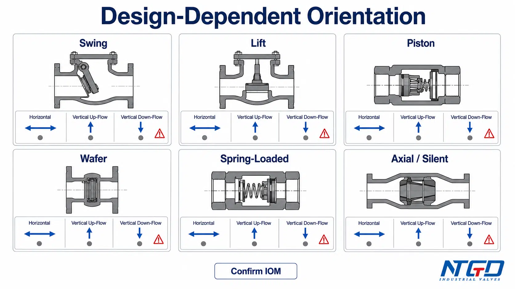
| Тип обратного клапана | Горизонтальный монтаж | Вертикальный восходящий поток | Вертикальный нисходящий поток | Обзор специальной установки |
|---|---|---|---|---|
| Поворотный обратный клапан | Нормально, если шарнир / крышка расположены правильно | Зависит от дизайна | Как правило, требует осторожности и подтверждения | Проверьте положение штифта петли, траекторию поворота диска и закрытие при обратном потоке. |
| Подъемный обратный клапан | Характерно для конструкций с горизонтальным подъемом | Только если конструкция предусмотрена для вертикального подъема или принудительного закрытия | Не предполагается | Убедитесь в правильном направлении хода диска/поршня и ориентации корпуса. |
| Поршневой обратный клапан | Часто горизонтальная, если конструкция не допускает иного расположения | Зависит от конструкции, особенно если предусмотрена пружинная поддержка | Не предполагается | Убедитесь в правильном ходе поршня и возврате под действием пружины. |
| Однодисковый / двухдисковый обратный клапан | Часто встречается в компактных трубопроводах | Часто возможно при использовании подходящих конструкций с пружинным приводом | Зависит от дизайна | Проверьте перемещение пластины, состояние пружины и зазор фланца. |
| Бесшумный / осевой обратный клапан | Часто подходит для проверки нагнетания насоса | Часто рассматривается для использования в вертикальных условиях или в условиях ограниченного пространства, в зависимости от конструкции | Зависит от дизайна | Уточните характеристики осевого закрытия, характеристики пружины и рекомендуемый участок прямой трубы. |
| Обратный клапан с пружинным приводом | Зачастую такие конструкции обладают большей гибкостью в плане ориентации, чем конструкции, зависящие от силы тяжести | Часто возможно, в зависимости от давления пружины и давления растрескивания | Только если это предусмотрено конструкцией | Уточните давление разрыва, расход и условия эксплуатации. |
| Шаровой обратный клапан | Зависит от дизайна | Некоторые конструкции могут требовать определённой ориентации | Зависит от дизайна | Убедитесь в правильном положении шарика, положении сиденья и соблюдайте инструкции производителя. |
Данная таблица представляет собой общее справочное пособие по техническим вопросам. Подробные ограничения по установке поворотных, подъемных, поршневых, пластинчатых, двухдисковых, бесшумных, осевых или пружинных обратных клапанов следует сверять с техническим описанием конкретного изделия и руководством по эксплуатации и обслуживанию (IOM) производителя. Таблица помогает определить направление поиска ответа; она не заменяет инструкции, относящейся к конкретному клапану.
Обратные клапаны качающегося типа и положение шарнирного штифта
Распашные обратные клапаны работают за счет диска или заслонки, закреплённых на шарнире. Положение шарнира и траектория поворота диска имеют решающее значение. Если шарнирный штифт ориентирован неправильно, диск может не открываться полностью, закрываться с задержкой при низком расходе или двигаться по нестабильной траектории закрытия при обратном потоке.
На многих промышленных объектах раскатные обратные клапаны тщательно проверяются на соответствие требованиям как для горизонтального, так и для вертикального (восходящего) потока. Окончательное решение следует принимать на основании руководства по эксплуатации производителя и проектной документации, особенно если трубопровод проходит вертикально или под уклоном. Для получения подробной информации о конструкции корпуса раскатного клапана, расположении шарнира и технических характеристиках изделия ознакомьтесь с поворотный обратный клапан Ознакомьтесь с данной страницей и руководством по эксплуатации клапана (IOM), прежде чем принимать решения о вертикальной или наклонной установке.
Конструкции с подъемником, поршнем и пружинным приводом
Рабочий принцип действия подъемных и поршневых обратных клапанов основан на направляемом движении запорного элемента. На возвращение диска или поршня в седло могут влиять сила тяжести, усилие пружины и направление потока. Некоторые конструкции предназначены для горизонтального монтажа, другие — для вертикальной эксплуатации.
Если в конструкции предусмотрен закрывающий элемент с направляемым поршнем, необходимо уточнить предельные значения для данного изделия в поршневой обратный клапан страница, подготовленная совместно с производителем IOM.
Конструкции с пружинным приводом могут обеспечивать большую гибкость в выборе ориентации, однако “пружинный привод” не означает автоматически, что устройство “подходит для всех положений”. Необходимо по-прежнему учитывать характеристики пружины, давление открытия, расход и состояние рабочей среды.
В конструкциях подъемного и поршневого типов вопрос монтажа заключается не только в том, “вертикально или горизонтально” их устанавливать. Речь идет о том, сможет ли направляемый запорный элемент вернуться на седло при фактическом расходе, ориентации и условиях обратного потока. Для конструкций подъемного типа необходимо проверить ориентацию корпуса и ход диска относительно обратный клапан подъема информация о продукте и проект IOM.
Конструкции с пластинкой, с двумя пластинами, бесшумные и с осевым потоком
Однодисковые и двухдисковые обратные клапаны широко используются в случаях, когда требуются компактные межфланцевые размеры. Бесшумные и осевые обратные клапаны часто рассматриваются в качестве вариантов для нагнетательной линии насоса, поскольку при правильном подборе и монтаже они способны быстро реагировать на изменение направления потока.
При использовании таких конструкций в ходе проверки монтажа необходимо убедиться в свободном перемещении тарелки или диска, исправности пружины, правильном зазоре между фланцами, правильном положении стрелки на корпусе, а также в соблюдении расстояния до источников турбулентности. Не следует устанавливать компактный обратный клапан в неудобном положении только потому, что он физически помещается в трубопроводе. В случае компактных схем трубопроводов пластинчатый обратный клапан На этой странице приведены более подробные сведения о зазоре между фланцами конкретных клапанов, их центрировании и ограничениях по установке.
Место установки рядом с насосами, коленями, тройниками и переходниками
Положение обратного клапана может повлиять на его стабильность работы. При установке обратного клапана вблизи нагнетания насоса, колена, тройника, переходника, расширителя, регулирующего клапана или частично открытого запорного клапана может возникать турбулентное течение. Турбулентное течение может привести к неравномерному усилию, действующему на диск, пластины, поршень или пружинный запорный элемент.
Практический риск заключается в цепной реакции: напор насоса или турбулентность в коленчатом участке создают асимметричный профиль скорости; на закрывающий элемент действует неравномерная сила открытия; диск или пластины могут частично открываться или входить в колебания; повторяющиеся движения затем ускоряют износ седла, шарнира, штифта, пружины или направляющих поверхностей.
Точные требования к расстоянию зависят от конструкции клапана, схемы трубопровода, скорости потока, рабочей среды и технических условий проекта. В некоторых проектах или инструкциях по эксплуатации и техническому обслуживанию (IOM) указываются минимальные длины прямых участков трубопровода до и после клапана. Эти значения следует уточнять с учетом конкретного клапана и условий эксплуатации, а не применять в качестве универсального правила.
| Фактор местоположения | Возможный риск | Действие по рассмотрению |
|---|---|---|
| Сразу после слива из насоса | Турбулентность, нестабильное закрытие, дребезг | Проверить схему расположения выпускного патрубка насоса и требования к длине прямого участка трубопровода. |
| Вблизи локтей | Неравномерный профиль скорости и асимметричная нагрузка на диск | Убедитесь, требуется ли перед клапаном прямой участок трубопровода. |
| Рядом с ти-пойнтами | Нарушение потока или неравномерность потока в ответвлениях | Убедитесь в правильном положении клапана и направлении трубопровода. |
| Рядом с редукторами / увеличителями | Изменение скорости, колебания давления | Убедитесь, что клапан установлен в режиме стабильного потока. |
| Рядом с регулирующими клапанами | Торможение турбулентности | Не устанавливайте обратный клапан в местах, где нестабильное течение может приводить к постоянному перемещению диска. |
| Рядом с фильтрами | Падение давления и скопление мусора | Убедитесь в возможности доступа для очистки и в условиях давления. |
| Ограниченный доступ для технического обслуживания | Сложность осмотра или демонтажа | Проверьте высоту подъема и рабочую зону. |
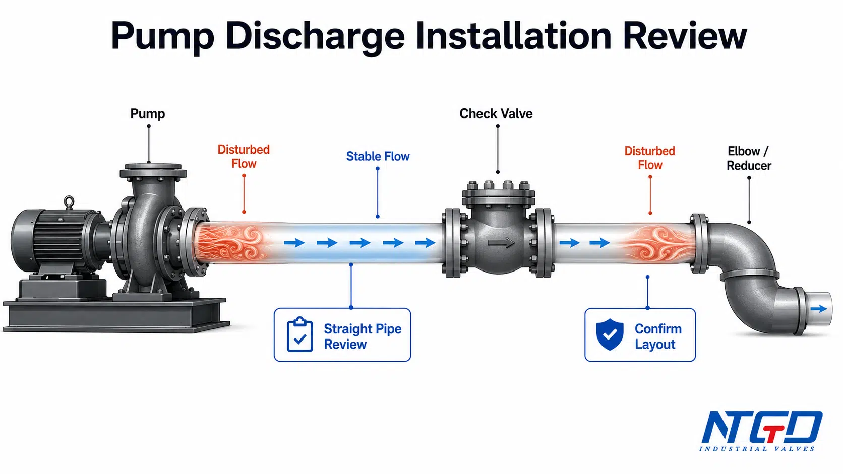
Расположение выпускного отверстия насоса и проверка прямых участков трубопровода
Во многих промышленных насосных системах на нагнетательном трубопроводе насоса устанавливается обратный клапан для предотвращения обратного потока после остановки насоса. Расположение клапана должно обеспечивать стабильный поток в обратный клапан и, по возможности, не должно приводить к его нахождению в зоне сильных турбулентностей, если это позволяет схема проекта.
Монтажник и инженер должны проверить:
- расположение насадки нагнетателя насоса;
- расположенные поблизости колена, тройники, переходники и компенсаторы;
- требования к длине прямого участка трубопровода, определяемые диаметром трубы, в соответствии с требованиями проекта или руководством по эксплуатации клапана;
- имеется ли доступ к клапану для проведения технического обслуживания;
- опирается ли груз клапана;
- могут ли условия запуска или выключения привести к резкому удару.
На вопрос “где следует устанавливать обратный клапан — до или после насоса?” невозможно ответить одним универсальным утверждением. Это зависит от назначения системы. При защите нагнетательной линии насоса от обратного потока обратный клапан, как правило, устанавливается на нагнетательной стороне. Другие задачи, такие как защита всасывающей линии, использование донного клапана или специальные технологические схемы, требуют отдельного инженерного анализа.
Если доступный прямой участок трубопровода ограничен, решением не должно быть принудительное включение того же самого клапана в схему без дополнительного анализа. Возможно, в рамках проекта потребуется пересмотреть схему прокладки трубопроводов, рассмотреть конструкцию клапана, более устойчивую к турбулентному течению, или запросить у производителя подтверждение возможности предлагаемой установки.
Статья по отраслевой тематике в Руководство по установке обратных клапанов от Valve Magazine Кроме того, в документе поясняется, что выбор клапанов, определение их размеров и монтаж трубопроводов следует рассматривать в комплексе, поскольку близость насоса и фитингов может приводить к возникновению турбулентности и преждевременному износу обратных клапанов.
Почему турбулентность может вызывать вибрацию, удары или износ
Обратный клапан должен открываться и закрываться в зависимости от режима потока. Если поток, поступающий в клапан, нестабилен, запорный элемент может не удерживаться в устойчивом положении. Он может колебаться, ударяться о седло, вибрировать или резко закрываться.
Это может привести к:
- вибрация обратного клапана;
- износ диска или пластины;
- повреждение сиденья;
- износ шарнира или пружины;
- шум и вибрация;
- риск гидравлического удара или скачка давления;
- преждевременное техническое обслуживание.
Установка не решает всех гидравлических проблем, но некачественный монтаж может привести к ненадёжной работе даже хорошего клапана. Именно поэтому необходимо комплексно анализировать схему нагнетания насоса, длину прямого участка трубопровода, тип клапана и проверки при вводе в эксплуатацию.
Выравнивание труб, их опоры и контроль напряжений
Обратный клапан не следует использовать для исправления неправильного расположения труб. Он не должен выдерживать вес трубы, не имеющей опоры, и его не следует вдавливать между фланцами, расположенными непараллельно друг другу.
Несоосность и напряжения в трубопроводе могут привести к деформации корпуса клапана, повреждению уплотнения фланца, нарушению внутреннего зазора и повышению риска утечки. Особое внимание следует уделять тяжелым обратным клапанам, клапанам большого диаметра, а также клапанам, установленным в системах с вибрирующими насосами.
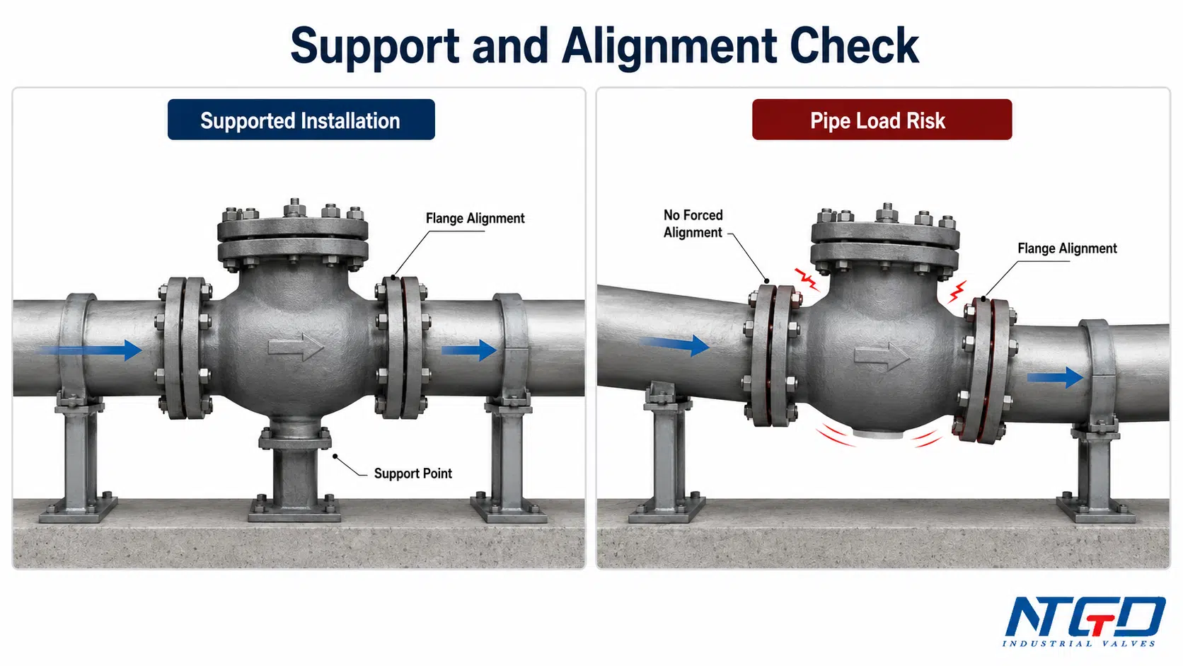
| Проверка опоры / выравнивания | Что нужно проверить | Риск сбоя |
|---|---|---|
| Опора трубы рядом с клапаном | Смежная труба имеет самостоятельную опору | Корпус клапана принимает на себя нагрузку от трубопровода. |
| Опора клапана | Тяжёлый клапан поднят и зафиксирован надлежащим образом | Напряжение в фланце, деформация корпуса, небезопасное обращение. |
| Выравнивание фланцев | Фланцы расположены параллельно и выровнены по центру | Повреждение прокладки, утечка, неравномерное затягивание болтов. |
| Затяжка болтов | Болты затягивались постепенно и равномерно | Деформация фланца или риск вырыва прокладки. |
| Без принудительной сборки | Труба не затягивается на место с помощью болтов клапана | Нагрузка на корпус и торцевые соединения. |
| Управление вибрацией | Проанализированы вибрация насоса и смещение труб | Усталость, ослабление креплений, шум, преждевременный износ. |
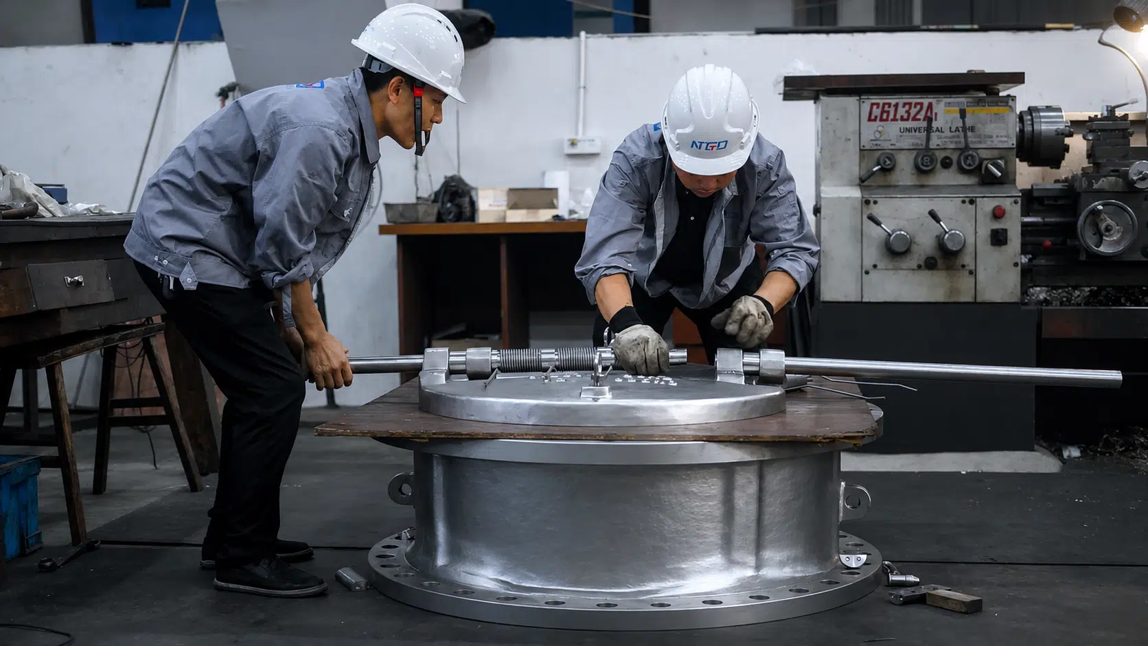
Обеспечить опору для массивных клапанов и прилегающих трубопроводов
С крупными обратными клапанами следует обращаться с помощью подходящего подъемного оборудования и устанавливать их таким образом, чтобы обеспечить опору для расположенных поблизости трубопроводов. Корпус клапана не должен служить единственной точкой опоры для длинного участка трубопровода.
Крупные вертикальные установки, обратные клапаны на выходе насосов и тяжелые фланцевые обратные клапаны часто требуют отдельной опоры, чтобы корпус клапана не выполнял функцию несущего элемента. Практический совет для работы на месте прост: если ослабление соседнего фланца приводит к провисанию трубы или клапана, перед запуском необходимо пересмотреть схему опоры.
Если клапан имеет большой вес, установлен в вертикальном трубопроводе или расположен вблизи нагнетания насоса, необходимо выяснить, требуются ли дополнительные опоры, направляющие или подвески. Конструкция опор должна соответствовать техническим условиям проекта на трубопроводы и инженерным требованиям объекта.
Следует избегать принудительного совмещения и напряжений в фланцах
Не используйте болты фланца для сближения несоосно расположенных концов труб. Это может привести к деформации корпуса клапана и возникновению длительных напряжений в соединении. Перед затяжкой убедитесь, что концы труб выровнены по центру, торцы фланцев расположены параллельно, а клапан естественным образом располагается в трубопроводе.
Для клапанов с тарелковым и двухпластинчатым затвором правильное расположение имеет особое значение, поскольку корпус зажат между фланцами, а тарелка или пластины должны иметь достаточный зазор для свободного перемещения.
Порядок монтажа промышленных обратных клапанов
Точная процедура монтажа зависит от типа клапана, типа соединения, проектных норм и правил техники безопасности на объекте. Приведенная ниже последовательность действий представляет собой общую схему промышленного монтажа.
| Шаг | Действие | Техническая проверка | Избегайте |
|---|---|---|---|
| 1 | Изолировать и сбросить давление в трубопроводе | Убедитесь в отсутствии давления и в безопасности условий работы | Открытие действующей или находящейся под давлением линии |
| 2 | Осмотрите клапан | Проверить стрелку корпуса, сиденье, диск, пружину, шарнир, торцевые крышки на наличие повреждений | Установка поврежденного или загрязненного клапана |
| 3 | Подтвердить чертежи | Соответствие маркировки клапана, номера линии, направления потока и ориентации | Установка правильного клапана в неправильном направлении |
| 4 | Подготовьте трубу | Очистите торцы труб, удалите мусор, проверьте торцевые поверхности фланцев | Оставление сварочного шлака или загрязнений внутри трубопровода |
| 5 | Установите клапан в нужное положение | Совместить стрелку на корпусе с предполагаемым направлением потока | Переключение входа и выхода |
| 6 | Подтвердить ориентацию | Проверить горизонтальное / вертикальное / наклонное положение в соответствии с IOM | При условии, что все обратные клапаны работают в любом положении |
| 7 | Установка по типу подключения | Следуйте инструкциям для фланцевых, вставных, сварных, резьбовых или канавчатых соединений | Воздействие на IOM теплом, крутящим моментом или герметиком |
| 8 | Затянуть и закрепить | Затягивайте равномерно; обеспечьте опору для тяжелого клапана и трубопровода | Принудительное выравнивание или вес клапана, не удерживаемый опорой |
| 9 | При необходимости повторно проверьте ход | По возможности проверьте зазор между диском и пластиной | Блокировка перемещения внутри здания |
| 10 | Начальные наблюдения при запуске | Оцените расход, утечки, уровень шума и особенности закрытия | Приемка установки без проверки работоспособности |
Изолировать, сбросить давление и проверить трубопровод
Перед установкой обратного клапана необходимо изолировать трубопровод и убедиться, что он находится в состоянии сброса давления, опорожнен и безопасен для проведения работ в соответствии с процедурами предприятия. Требования к блокировке, изоляции и сбросу давления зависят от системы безопасности предприятия и характера рабочей среды.
Не приступайте к монтажным работам, ориентируясь исключительно на положение клапана. Убедитесь в фактическом состоянии трубопровода.
Установите клапан и проверьте направление потока
Установите клапан так, чтобы стрелка на корпусе указывала в направлении предполагаемого потока. Сравните положение стрелки с данными на схеме P&ID, изометрическом чертеже трубопроводов, бирке клапана и направлением потока в трубопроводе.
Если стрелка на корпусе противоречит чертежу, не следует считать, что чертеж или клапан верны. Прервите работу и проконсультируйтесь со специалистами проектного отдела или производителем, прежде чем продолжать монтаж.
Установка в зависимости от типа подключения без перегрузки клапана
Тип соединения влияет на особенности монтажа. Цель заключается не только в обеспечении герметичности соединения, но и в защите корпуса клапана и внутреннего запорного элемента от нагрева, деформации, попадания посторонних частиц, чрезмерного крутящего момента или механического воздействия.
| Тип соединения | Проверка установки ключей | Распространенная ошибка, которую следует избегать |
|---|---|---|
| Фланцевый обратный клапан | Убедитесь в правильном положении прокладки, выравнивании фланцев, длине болтов и постепенной затяжке болтов поперекрестным способом в соответствии с требованиями проекта | Стягивание несовмещенных фланцев с помощью болтов или чрезмерная затяжка сначала одной стороны |
| Обратный клапан с пластинкой / выступом | Выровняйте клапан по центру между фланцами и проверьте зазор между диском и пластиной | Допущение того, чтобы движение диска приводило к соприкосновению с торцами фланцев, болтами или прокладками |
| Сварной обратный клапан | Соблюдайте утвержденную процедуру сварки и, при необходимости, защищайте внутренние детали от воздействия высокой температуры и попадания обломков | Сварка без защиты седла, пружины, диска или внутреннего проходного канала |
| Обратный клапан с резьбовым соединением | Убедитесь в правильной затяжке резьбы и используйте герметик, совместимый с условиями эксплуатации и руководством по эксплуатации (IOM) | Попадание излишков герметика в область седла или чрезмерное затягивание корпуса |
| Оборотистый обратный клапан | Убедитесь в правильном соединении, плотности прилегания прокладки, соответствии размеров пазов и правильной центровке | Установка муфты при несовпадении оси клапана или трубы |
Способ подключения не должен создавать избыточную нагрузку на корпус клапана или препятствовать работе внутреннего запорного элемента.
Затяните, зафиксируйте и еще раз проверьте выравнивание
После установки клапана в трубопровод затягивайте соединения постепенно и равномерно. Перед вводом в эксплуатацию еще раз проверьте совмещение фланцев, опору клапана, направление стрелки на корпусе и окончательную ориентацию. В случае с крупногабаритными клапанами убедитесь, что подъемное оборудование снято только после того, как клапан и прилегающие трубопроводы будут полностью закреплены на опорах.
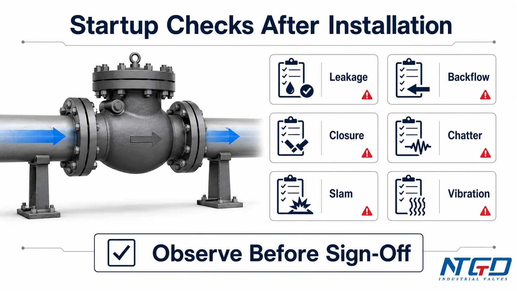
Проверки при запуске и вводе в эксплуатацию после монтажа
Установка обратного клапана не считается завершённой после затяжки болтов. Во время запуска и на начальном этапе эксплуатации необходимо наблюдать за работой клапана. Проверки при запуске позволяют убедиться, что клапан открывается при прямом потоке и закрывается при обратном потоке.
| Проверка стартапа | Допустимое наблюдение | Предупреждающий знак | Действие |
|---|---|---|---|
| Внешняя утечка | Отсутствие утечек на фланцах, стыках корпуса, резьбовых соединениях и сварных швах | Капание, просачивание, разрыв прокладки | Остановитесь и проверьте соединение, прокладку, крепеж, выравнивание или место сварки. |
| Проходной канал | Система обеспечивает ожидаемый прямой поток | Низкий расход, большие потери давления, отсутствие расхода | Проверьте направление, наличие препятствий, степень открытия клапана, а также соответствие выбранной конструкции условиям эксплуатации. |
| Закрытие | Клапан закрывается при начале обратного потока | Обратный поток продолжается | Проверьте ориентацию, посадку, пружину, диск, поршень, пластину или неправильное направление установки. |
| Болтовня | Закрывающий элемент сохраняет стабильность | Повторные удары или вибрация | Сначала определите направление и ориентацию потока; затем проанализируйте прямой участок трубопровода, источники турбулентности, размеры арматуры и фактический расход. |
| Слэм | Плавная остановка при завершении работы | Громкий удар или скачок давления | Проанализируйте поведение насоса при остановке, условия обратного потока, реакцию клапанов, а также необходимость применения другой конструкции. |
| Вибрация | Отсутствие аномальной вибрации труб или клапанов | Колебания вблизи насоса или колена трубопровода | Проверить опоры, выравнивание, состояние потока вверх по течению и смещение трубы. |
| Шум | Нормальный рабочий шум | Стук, грохот или нестабильный шум | Сравните симптом с направлением потока, ориентацией, расстоянием между элементами и стабильностью замыкания. |
| Характеристики сидений | Утечка в обратном направлении не превышает допустимых для проекта пределов | Обратная утечка или нарушение герметичности | Проверьте наличие мусора, повреждений, неправильной ориентации или несоответствия типа клапана. |
Проверка на утечку, обратный поток и закрытие
Во время запуска проверьте клапан и соседние соединения на наличие внешних утечек. Затем убедитесь, что клапан обеспечивает нормальный прямой поток и закрывается при начале обратного потока. При эксплуатации насоса в режиме нагнетания обратите внимание на его поведение при запуске и остановке, поскольку некоторые неисправности проявляются только при переходе от одного режима потока к другому.
Если клапан не закрывается, возможными причинами могут быть: неправильное направление установки, несоответствующее расположение, загрязнение седла, повреждение внутренних деталей, недостаточный расход или использование клапана неподходящего типа.
Обзор вибрации, ударов, колебаний и шума
Не следует игнорировать стук или грохот, возникающие после монтажа. Это может свидетельствовать о нестабильном потоке, выборе клапана слишком большого размера, неправильной схеме выпускного трубопровода насоса, неправильной ориентации, недостаточной опоре или конструкции клапана, не соответствующей условиям эксплуатации.
Если при запуске наблюдается дребезг или хлопок, при первоначальном анализе не следует сразу делать вывод о наличии внутренних повреждений. Начните с проверки условий монтажа: направления потока, ориентации, длины прямого участка, источников турбулентности, крепления трубы, а также того, соответствует ли тип клапана фактическому диапазону расхода.
Проверка установки позволяет снизить очевидные риски, но не может устранить все переходные явления в сложной системе. Если в системе наблюдается резкое отключение насоса, имеются длинные нагнетательные трубопроводы, сильные скачки давления или повторяющиеся удары, может потребоваться более подробный инженерный анализ.
Для насосных систем с быстрым отключением, высоким статическим напором или повторяющимися ударами, Часто задаваемые вопросы о насосах от Гидравлического института отмечает, что закрытие обратного клапана может вызвать гидравлический удар, поэтому необходимо проанализировать сложные переходные процессы, выходящие за рамки базового контрольного списка по монтажу.
Распространенные ошибки при монтаже обратных клапанов
Многие неисправности обратных клапанов вызваны не только конструкцией самого корпуса клапана. Их причиной зачастую являются ошибки при монтаже, которые влияют на направление потока, работу внутренних механизмов, надежность закрытия или механические нагрузки.
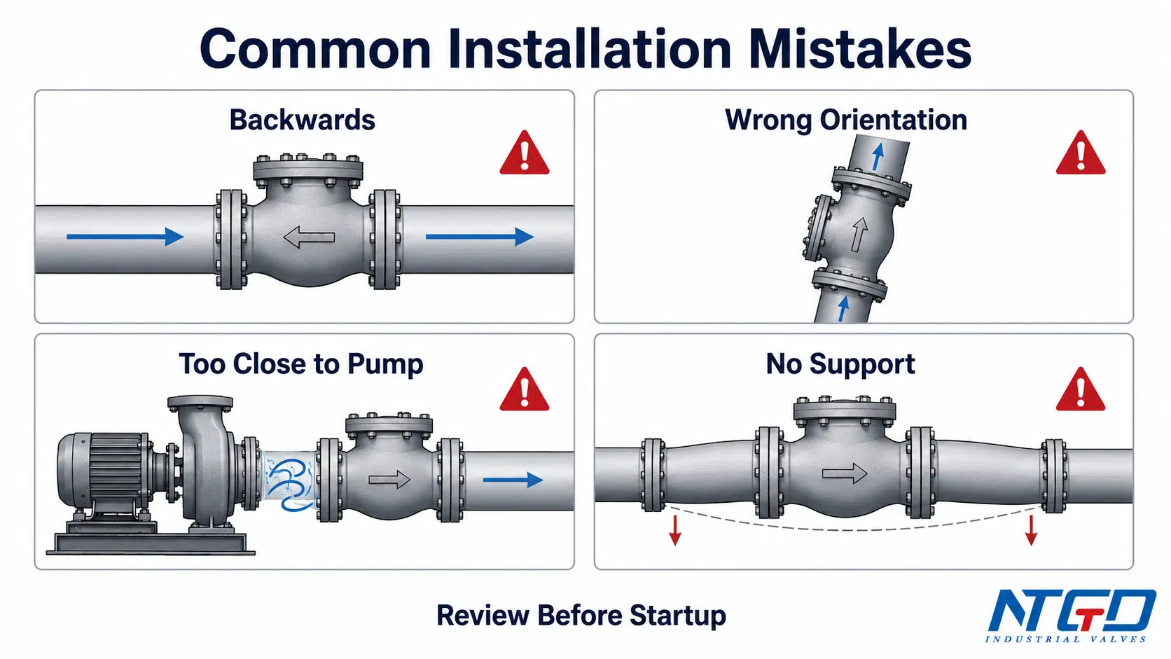
| Ошибка | Возможные последствия | Профилактика |
|---|---|---|
| Установка клапана в обратном направлении | Отсутствие потока в прямом направлении, сбой защиты от обратного потока, сбой при запуске | Перед затяжкой проверьте расположение стрелки на корпусе, чертеж, направление линии и данные IOM. |
| Предположим, что любой клапан может быть установлен вертикально | Диск, поршень или пластина могут не закрываться должным образом | Уточните конструкцию клапана и допустимые варианты его установки. |
| Игнорирование риска вертикального нисходящего потока | Сбой при закрытии или нестабильная работа | Используйте только в том случае, если производитель подтвердил пригодность данного изделия. |
| Установка слишком близко к зоне турбулентности насоса | Шум, удары, вибрация, износ | Ознакомьтесь со схемой нагнетания насоса и требованиями к прямым участкам трубопровода. |
| Установка вблизи колен или переходников без предварительной проверки | Неравномерное течение и нестабильное закрытие | Перед установкой клапана проверьте схему прокладки трубопровода. |
| Отсутствие опоры для трубы | Напряжение в корпусе, утечка из фланца, вибрация | Обеспечьте опору для прилегающих трубопроводов и массивных клапанов. |
| Принудительное центрирование фланцев | Повреждение прокладки, утечка, деформация корпуса | Перед монтажом выровняйте трубопроводы. |
| Оставление мусора на трассе | Повреждение сиденья или отказ замка | Перед запуском необходимо очистить трубу и проверить клапан. |
| Неправильный тип клапана для данного применения | Частые стуки, утечки, короткий срок службы | Перед установкой ознакомьтесь с условиями обслуживания. |
| Разрешить установку без проверок при запуске | Проблемы со скрытыми застежками или вибрацией | Во время запуска обратите внимание на утечки, герметичность, обратный поток, шум и вибрацию. |
Если обнаружена какая-либо из этих ошибок, не переходите сразу к утверждению ввода в эксплуатацию. Сначала устраните ошибку монтажа. Наличие нескольких ошибок может усугубить риск: неправильно установленный клапан, недостаточный прямой участок трубопровода и отсутствие опор могут в совокупности привести к блокировке потока, вибрации, риску гидравлического удара, утечке через фланцы и преждевременному внутреннему износу. Если вы не уверены в пригодности клапана или правильности его расположения, воспользуйтесь приведенным ниже контрольным списком для запроса предложений (RFQ) и руководством по эксплуатации (IOM), чтобы запросить техническую экспертизу перед окончательной приемкой.
Ошибки, влияющие на направление и ориентацию потока
Самая серьезная ошибка при монтаже — установка клапана в обратном направлении. Установленный в обратном направлении обратный клапан может препятствовать предусмотренному прямому потоку или не способен остановить обратный поток. Еще одна распространенная ошибка — правильное направление потока при неправильной ориентации корпуса. Это особенно опасно для конструкций, работающих за счет силы тяжести.
Если направление или ориентация неясны, установку следует проверить, сверяясь с биркой клапана, схемой P&ID, изометрическим чертежом, стрелкой на корпусе и руководством по эксплуатации производителя.
Ошибки, влияющие на стабильность и срок службы
Обратный клапан, установленный в условиях нестабильного потока, может вибрировать даже при правильном направлении и ориентации. Повторяющиеся движения могут привести к повреждению седла, диска, шарнира, штифта, пружины или контактных поверхностей корпуса. Ненадлежащая опора и принудительное выравнивание могут создавать дополнительную механическую нагрузку, сокращающую срок службы.
Надежная установка должна обеспечивать правильный подбор клапанов, правильное направление, надлежащую ориентацию, достаточное расстояние между элементами, надлежащую опору и проверку при вводе в эксплуатацию.
Часто задаваемые вопросы об установке обратного клапана
Можно ли установить обратный клапан вертикально?
Да, некоторые обратные клапаны можно устанавливать вертикально, но ответ зависит от трёх факторов: конструкции клапана, направления потока и руководства по эксплуатации и техническому обслуживанию (IOM) производителя. Вертикальный поток вверх часто проще оценить, чем вертикальный поток вниз, поскольку прямой поток может способствовать подъёму запорного элемента, а обратный — его закрытию. Окончательное решение следует принимать с учётом конкретной модели клапана и условий эксплуатации.
Можно ли установить обратный клапан в горизонтальном положении?
Многие промышленные обратные клапаны можно устанавливать в горизонтальном положении, однако перед монтажом необходимо провести проверку проекта. Перед вводом в эксплуатацию необходимо убедиться в правильном направлении стрелки на корпусе, положении крышки или шарнира, механизме закрытия, креплении трубопровода, а также ознакомиться с инструкциями производителя.
Следует ли устанавливать обратный клапан вертикально или горизонтально?
Выбор зависит от конструкции клапана, направления потока, рабочей среды, расхода, давления открытия, схемы расположения насосов и требований IOM. Не следует выбирать вертикальный или горизонтальный вариант монтажа только из-за удобства прокладки трубопровода.
В каком направлении следует устанавливать обратный клапан?
Обратный клапан следует устанавливать так, чтобы стрелка на корпусе указывала в направлении нормального потока вперед. Соответствие стрелки следует проверить по схеме P&ID, изометрическому чертежу трубопровода, направлению потока, бирке клапана и руководству по эксплуатации производителя. Подробную информацию о направлении потока в обратном клапане, обозначении входа и выхода, а также признаках неправильной установки см. в специальном руководстве по направлению потока.
Где следует установить обратный клапан?
В промышленных трубопроводах положение установки обратного клапана зависит от назначения системы. Для защиты нагнетательной линии насоса от обратного потока клапан обычно устанавливается на нагнетательной стороне насоса, однако его точное расположение зависит от конфигурации насоса, длины прямого участка трубопровода, уровня турбулентности, доступности и технических требований проекта.
Обратный клапан следует устанавливать до или после насоса?
Во многих случаях при нагнетании жидкости обратный клапан устанавливается ниже по потоку от насоса, чтобы уменьшить обратный поток после остановки насоса. Однако не во всех системах используется одинаковая схема монтажа. Правильное расположение следует уточнять в соответствии с проектом системы, техническими условиями проекта и рекомендациями производителя.
На каком расстоянии от насоса следует устанавливать обратный клапан?
Не существует единого значения расстояния, применимого ко всем обратным клапанам и всем насосам. Во многих промышленных проектах прямой участок трубопровода на выходе из насоса рассматривается как зазор, рассчитанный исходя из диаметра трубы, вокруг насосов, колен, переходников и других источников турбулентности. Правильное расстояние следует определять с учётом типа клапана, модели насоса, предполагаемого расхода, схемы трубопровода, технических условий проекта и рекомендаций производителя по монтажу.
Если предлагаемая схема не обеспечивает достаточный прямой участок трубопровода, отправьте схему производителю на рассмотрение. Решением может стать выбор клапана другой конструкции, изменение схемы прокладки трубопроводов или проведение дополнительного инженерного анализа, а не слепое следование правилу о фиксированном расстоянии без учета конкретных условий.
Что произойдет, если обратный клапан установить задом наперед?
Если обратный клапан установлен в неправильном положении, он может препятствовать прямому потоку, не предотвращать обратный поток, вызывать аномальную потерю давления или приводить к проблемам при запуске. В крайних случаях может произойти повреждение внутреннего запорного элемента или седла.
Все ли обратные клапаны допускают вертикальный поток вниз?
Нет. Вертикальный нисходящий поток зависит от конструкции, и его нельзя считать допустимым. Некоторые типы обратных клапанов могут не закрываться надёжно при работе с нисходящим потоком, если они не были специально разработаны и одобрены для такой ориентации.
Можно ли установить качающийся обратный клапан в вертикальном положении?
Некоторые поворотные обратные клапаны могут допускаться к эксплуатации в вертикальных трубопроводах с восходящим потоком, однако необходимо проверить положение шарнира, ход диска, направление потока и руководство по эксплуатации (IOM). При обращении к производителю с просьбой подтвердить пригодность клапана необходимо указать его размер, ориентацию трубопровода, направление потока и условия эксплуатации. Подробные требования к монтажу поворотных обратных клапанов следует изучить в соответствующей технической документации по данному типу клапанов.
Можно ли установить поршневой обратный клапан вертикально?
Поршневой обратный клапан может требовать определённой ориентации, поскольку поршень должен правильно возвращаться в седло. Некоторые конструкции с пружинным возвратом могут допускать дополнительные варианты ориентации, однако это необходимо уточнить в руководстве по эксплуатации и техническому обслуживанию (IOM). При вертикальной установке необходимо учитывать ход поршня, пружинный возврат, давление открытия, фактический расход и состояние рабочей среды.
Можно ли устанавливать пластинчатые обратные клапаны в вертикальном положении?
Некоторые клапаны с прокладкой или с двумя пластинами могут эксплуатироваться в вертикальном положении, особенно если их конструкция предусматривает соответствующее пружинное усилие. Однако перед монтажом необходимо проверить ход пластины, состояние пружины, направление потока, зазор между фланцами и расположение насоса. Окончательный ответ следует искать в конкретной конструкции клапана с прокладкой или с двумя пластинами, а также в инструкциях производителя.
Анализ запросов на предложение (RFQ) и IOM: что необходимо уточнить перед размещением заказа или установкой
В случае промышленных проектов проверка монтажа должна начинаться до отгрузки клапана на объект. Если клапан будет устанавливаться рядом с насосом, в вертикальной линии, в условиях компактной схемы трубопроводов или в системе, характеризующейся высокой частотой циклов работы, вибрацией, присутствием твердых частиц, быстрым отключением или риском обратного потока, условия монтажа должны быть указаны в запросе предложений и учтены при технической экспертизе.
Своевременное предоставление этих условий помогает поставщику оценить пригодность клапана до его доставки на объект. Это особенно важно в случаях, когда в рамках проекта предусмотрен вертикальный монтаж, ограниченное пространство для нагнетания насоса, использование специальных сред, наличие твердых частиц, быстрое отключение насоса, риск вибрации или короткий прямой участок трубопровода.
| Данные по установке | Почему это важно |
|---|---|
| Тип клапана | Ориентация и особенности закрытия зависят от конструкции. |
| Размер и класс давления | Подтверждает механическое прилегание и герметичность. |
| Концевое соединение | Тип монтажа — фланцевый, вставной, с ушками, приварной, резьбовой или с пазом — влияет на удобство эксплуатации. |
| Материал корпуса и отделки | Подтверждает совместимость среды и температуры. |
| Среда и температура | Влияет на материал сиденья, пружину, коррозию и герметичность. |
| Нормальный и минимальный расход | Низкий расход может повысить риск возникновения вибрации. |
| Место установки насоса | Конфигурация нагнетания насоса влияет на турбулентность и динамику работы клапанов. |
| Горизонтальная / вертикальная ориентация | Подтверждает, подходит ли данная конструкция. |
| Расположенные поблизости колена, тройники, переходники | Помогает проанализировать риски, связанные с прямыми участками трубопровода и турбулентностью. |
| Доступ к установке | Влияет на проведение осмотров, подъемных работ и техническое обслуживание. |
| МОМ / Техническое задание проекта | Определяет окончательные пределы установки. |
| Критерии приемки стартапа | Помогает подтвердить соответствие ожиданиям в отношении утечек, герметичности, шума и вибрации. |
Данные по установке, которые необходимо предоставить NTGD
При заказе обратного клапана для промышленного проекта необходимо указать тип клапана, размер, класс давления, материал, тип соединения, рабочую среду, температуру, направление потока, ориентацию при монтаже, расположение насоса и схему прокладки трубопроводов вблизи. Если требуется вертикальный монтаж или длина прямого участка трубопровода ограничена, следует указать эту информацию на раннем этапе.
Это помогает NTGD оценить, подходит ли выбранная конструкция обратного клапана для реальных условий монтажа, а не только для номинального размера трубы. Такая оценка может способствовать проверке соответствия монтажу, подтверждению инструкции по эксплуатации, анализу схемы нагнетания насоса, а также раннему выявлению рисков, связанных с ориентацией или расстояниями.
Когда следует обратиться к производителю за подтверждением
Обратитесь к производителю за подтверждением в следующих случаях:
- клапан будет установлен вертикально;
- клапан расположен рядом с нагнетанием насоса;
- требуется вертикальный нисходящий поток;
- в линии имеется короткий прямой отрезок трубы;
- в системе наблюдается интенсивный циклический режим работы или резкое отключение насоса;
- в среде присутствуют твердые частицы или загрязнения;
- клапан большой или тяжёлый;
- доступ к установке для технической поддержки или обслуживания ограничен;
- Техническое задание проекта предусматривает подготовку специальной документации.
Подтверждение со стороны производителя не заменяет инженерную ответственность, но помогает избежать несоответствий между конструкцией клапана и схемой монтажа.
Заключение
Установку обратного клапана следует рассматривать как инженерную экспертизу, а не просто как операцию по монтажу на месте. Надежная установка позволяет подтвердить направление потока, ориентацию, конструкцию клапана, положение нагнетания насоса, расстояние между трубами, крепление, выравнивание и поведение при запуске.
Наиболее безопасный подход заключается в том, чтобы проверить направление стрелки на корпусе относительно направления потока, убедиться в соответствии горизонтальной или вертикальной установки конструкции клапана, по возможности избегать нестабильных режимов потока, обеспечить опору для клапана и прилегающих трубопроводов, а также следить за утечками, обратным потоком, дребезжанием, ударами, вибрацией и закрытием клапана во время запуска.
Правильная установка обратного клапана является результатом тщательного инженерного анализа, а не случайным результатом монтажа на месте. Перед сдачей в эксплуатацию необходимо проверить установку на соответствие техническим условиям, утвержденному комплекту чертежей, руководству по эксплуатации производителя и фактическому поведению системы при запуске.
Поддержка приложений / спецификаций
NTGD может оказать поддержку в подборе промышленных обратных клапанов и проверке их монтажа в тех случаях, когда в рамках проекта требуется подтвердить тип клапана, его размер, класс давления, материал изготовления, направление потока, вертикальную или горизонтальную ориентацию, схему нагнетания насоса, состояние прямого участка трубопровода, а также соответствие требованиям руководства по эксплуатации (IOM).
Если в ходе проверки монтажа выяснится, что требуется иная форма корпуса или конструкция замыкающего устройства, используйте обратный клапан категорию товара в качестве следующего этапа выбора перед подтверждением запроса на предложение.
Для рассмотрения запроса на предложение укажите среду, температуру, класс давления, тип соединения, ориентацию при монтаже, расположение насоса, наличие поблизости колен или переходников, а также любые специфические для проекта требования к расстояниям или пусковым работам.
