Author Name: Bruce Zheng
Author Role: Co-Founder and Valve Engineer at NTGD Valve
Author Bio: Bruce Zheng is Co-Founder and Valve Engineer at NTGD Valve, focusing on industrial valve selection, application, and technical content for global B2B buyers.
Last Updated: June 15, 2026
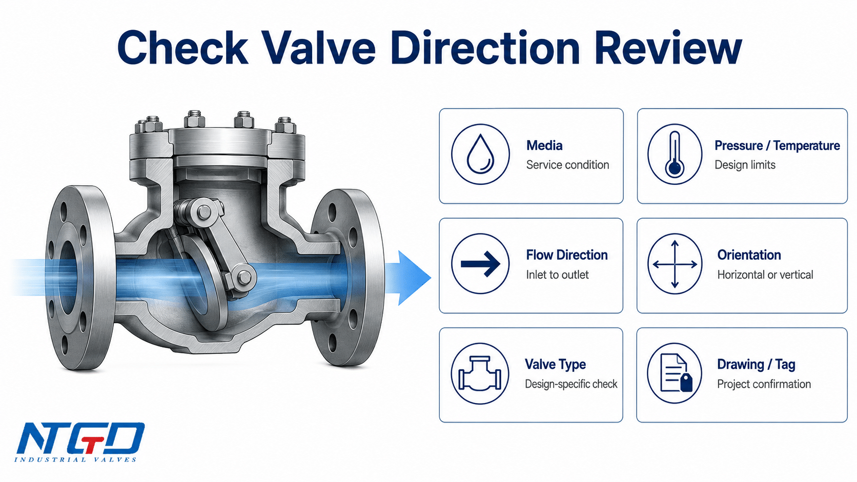
Check valve flow direction is the intended direction of flow through the physical valve body. In most industrial installations, this direction should match the arrow, FLOW marking, or IN / OUT marking on the valve body. The arrow normally points from the inlet side toward the outlet side, showing the direction in which the check valve is designed to open under forward flow.
This matters because a check valve is not a simple open pipe fitting. Its internal disc, plate, ball, piston, poppet, or flapper is designed to open in one direction and close against reverse flow. If the valve is installed in the wrong direction, the closure element may not open properly, backflow protection may fail, or the system may experience abnormal pressure, noise, vibration, or water hammer risk.
This guide focuses on physical check valve flow direction: valve body arrows, installation direction, horizontal and vertical orientation, and wrong-flow risks. It does not replace the manufacturer’s IOM, project drawing, datasheet, or valve tag. It is also not a complete P&ID symbol guide, hydraulic schematic guide, or full installation manual.
Quick Answer: Which Way Should a Check Valve Flow?
The short answer for valve body arrows
A check valve should normally be installed so that the valve body arrow points in the same direction as the intended process flow. In simple terms:
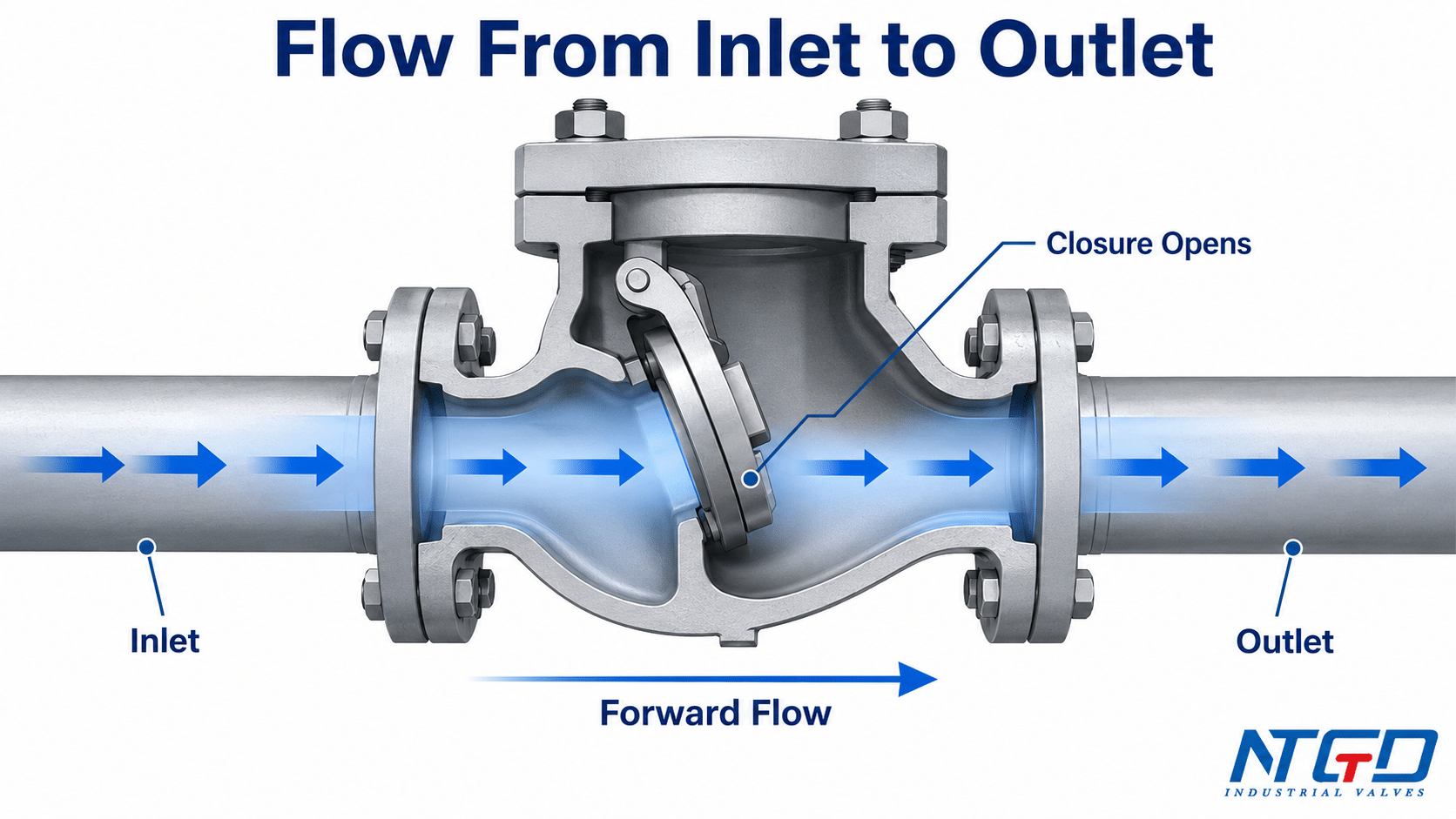
Flow should enter the inlet side, push the closure element open, pass through the valve, and leave from the outlet side.
If the body is marked with FLOW, IN, OUT, or a cast arrow, that marking should be checked before the valve is tightened into the line. If the arrow conflicts with the project drawing, valve tag, or installation position, the installation should stop until the manufacturer’s documentation or project engineer confirms the correct orientation.
For most standard check valves, the valve is directional. It is designed to allow forward flow and help prevent reverse flow. It should not be installed casually in either direction unless the manufacturer clearly states that the specific design allows it.
As an external industry reference, Valve Magazine check valve installation reference also notes that the flow arrow should point in the direction of flow and that the valve type must suit the installed position.
If the arrow points opposite to the intended forward flow, the valve may not open correctly, backflow protection may be lost, and the system may develop abnormal pressure behavior or water hammer risk.
What this guide covers and what it does not cover
This guide explains physical valve body flow direction and body arrow markings. It does not explain P&ID check valve symbols, hydraulic schematic symbols, or drawing-symbol flow direction in detail; those are separate topics.
This guide covers:
- how to understand check valve flow direction;
- how to read a valve body arrow or FLOW marking;
- how flow direction relates to inlet, outlet, and internal closure direction;
- why valve design affects installation orientation;
- what can happen if a check valve is installed backwards;
- how to verify direction when the body arrow is missing, hidden, painted over, or unclear.
This guide does not provide:
- a full P&ID or hydraulic symbol guide;
- a full installation procedure for every check valve design;
- bolting torque, gasket installation, welding procedure, pipe support design, or commissioning methods;
- detailed flow-direction rules for every specific check valve type.
Those items should be verified against the project specification, valve datasheet, and manufacturer IOM. Clarifying these boundaries before installation helps reduce the risk of field rework, wrong valve placement, and avoidable commissioning delays.
What Does Check Valve Flow Direction Mean?
Flow from inlet to outlet
Check valve flow direction means the intended path of fluid through the valve body. In an industrial piping system, this direction is usually defined by:
- the process flow direction in the piping layout;
- the valve body arrow or FLOW marking;
- the manufacturer’s drawing or datasheet;
- the valve tag or line list;
- the internal closure design of the check valve.
The inlet side is the side where forward flow enters the valve. The outlet side is the side where forward flow leaves the valve. When the valve is installed correctly, forward flow should push the closure element away from the seat and create an open flow path.
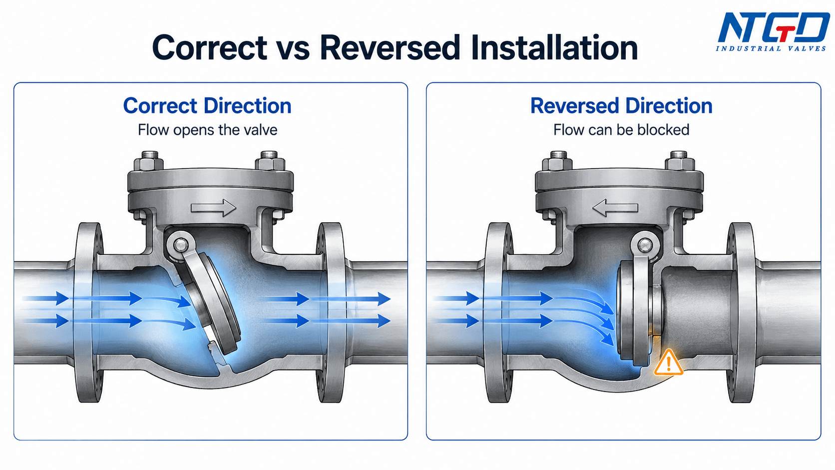
If the valve is installed in the opposite direction, the flow may push the closure element into the seat instead of opening it. The result may be no flow, restricted flow, abnormal pressure buildup, or unstable operation.
Forward flow, reverse flow and backflow prevention
A check valve is commonly used to allow flow in one direction and help prevent reverse flow. During forward flow, line pressure and flow force open the internal closure element. When flow slows, stops, or starts to reverse, gravity, reverse pressure, spring force, or a combination of these forces helps move the closure element back toward the seat.
The exact closing behavior varies by closure mechanism, body geometry, spring arrangement, and guide design. A swing check valve closes differently from a lift check valve, piston check valve, dual-plate check valve, or spring-assisted check valve. This is why flow direction and installation orientation should be checked against the specific valve design instead of assumed from a generic rule.
For broader terminology, NTGD explains how an NRV valve guide relates non-return valves, check valves and one-way valves in industrial piping systems.
If the reader needs a broader comparison of closure mechanisms, the check valve types guide can be used as the next reference instead of expanding this flow-direction article into a full type overview.
How to Read the Check Valve Flow Arrow
Valve body arrow, FLOW marking and IN / OUT marking
The most direct way to identify check valve flow direction is to inspect the valve body. Industrial check valves may use one or more markings, such as:
- a cast or stamped flow arrow;
- the word FLOW with an arrow;
- IN and OUT markings;
- a valve tag or nameplate reference;
- a manufacturer drawing that shows the inlet and outlet side.
The flow arrow should normally point in the direction of intended forward flow. If the system flow is from left to right on the drawing, the installed valve body arrow should also point from left to right in the field, unless the project drawing or manufacturer documentation specifies a different arrangement.
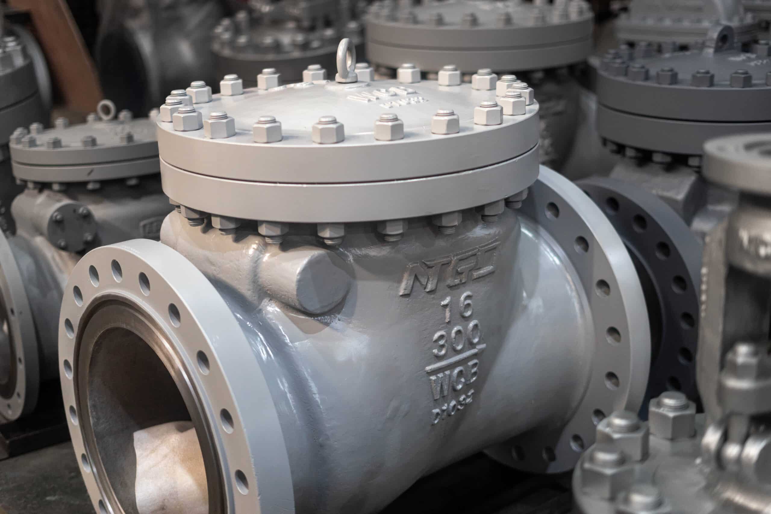
For large flanged check valves, the arrow may be cast into the body and may be partially covered by coating, insulation, pipe position, or site access limitations. Direction should be confirmed before final tightening, not after the valve has been fully installed.
Inlet side, outlet side and internal closure direction
The body arrow is not just a convenient marking. It normally reflects how the internal closure element is intended to move.
A correctly oriented check valve should allow forward flow to push the disc, plate, ball, poppet, or piston away from the seat. The valve then opens as the flow force exceeds the resistance of the closure element, gravity, spring, or internal guide arrangement.
When flow direction is reversed, the same internal element may be forced against the seat. This can block the flow path or prevent the valve from operating as intended. In some cases, the system may build pressure upstream of the valve while downstream equipment receives little or no flow.
Do not rely only on exterior body shape when the internal flow path is not obvious. Y-pattern check valves, stop check valves, and some special body designs may require the body arrow, product drawing, valve tag, or IOM to confirm the true inlet and outlet arrangement.
For stop-check applications, review the dedicated stop check valve page before treating the internal flow path as a simple inline check-valve arrangement.
For angled body designs, the Y-check valve page is the better place to review how the disc, ball or spring arrangement affects inlet, outlet and installation judgment.
Why the arrow should not be ignored during installation
A check valve arrow should not be treated as a decorative mark. It is a direction control reference.
Ignoring the arrow can create several problems:
- the valve may not open under normal forward flow;
- the system may lose backflow protection;
- pump discharge or process equipment may see abnormal pressure behavior;
- the valve may chatter, slam, or create unstable noise;
- troubleshooting becomes more difficult because the installed position contradicts the intended design.
In critical service, pump discharge, high-pressure service, steam service, or other transient-sensitive systems, a wrong flow direction can increase equipment stress and water hammer risk beyond simple troubleshooting inconvenience.
If the arrow is missing or unclear, the correct response is not to guess. The installer should check the valve drawing, tag, line list, IOM, or manufacturer documentation before proceeding.
Body Arrow vs P&ID Symbol vs Manufacturer IOM
A common source of confusion is the difference between a physical valve body arrow, a P&ID or drawing symbol, and the manufacturer’s installation documentation. These items are related, but they do not have the same function.
| Source | What it tells you | What it cannot confirm by itself | When to verify |
|---|---|---|---|
| Valve body arrow | The intended physical flow direction through that valve body | Whether the valve matches the correct line, tag, or service condition | Always before final installation |
| FLOW / IN / OUT marking | Which side should face inlet or outlet flow | Whether the project drawing has changed or the valve has been substituted | When markings and drawing need cross-checking |
| P&ID symbol | The design intent and process flow logic on the drawing | The physical valve’s actual internal construction, body marking, field orientation, and suitability for that service | When transferring drawing information to site installation |
| Manufacturer IOM | Installation, orientation, operation, and service cautions for the specific design | Project-specific piping changes unless included in project documents | When direction, vertical orientation, or service condition is uncertain |
| Valve tag / valve list | Which valve belongs to which line and service | Internal construction details unless linked to datasheet or drawing | When multiple check valves are similar in appearance |
A common field error is assuming that the drawing flow arrow automatically matches the physical valve orientation. Before final installation, the valve body marking, valve tag, and project documents should be cross-checked together.
What the valve body arrow tells you
The valve body arrow is the strongest field-level clue for physical flow direction. It normally tells the installer which way the medium should pass through the valve body.
However, the body arrow still needs to be checked against the project documents. A valve can have a correct arrow but still be installed in the wrong line, wrong orientation, or wrong service condition.
What a P&ID or drawing arrow can and cannot confirm
A P&ID or process drawing may show process flow direction and valve position in the system. It helps engineers understand how the system is intended to operate.
But a drawing symbol is not the same as a physical body arrow. A drawing can confirm design intent, but it cannot replace field verification of the actual valve marking, tag, size, pressure class, end connection, internal construction, and installation orientation.
When to stop and check the IOM, tag or valve list
Installation should stop for verification when:
- the body arrow is missing or unreadable;
- the arrow conflicts with the piping drawing;
- the valve tag does not match the line list;
- the valve is installed in a vertical line and orientation matters;
- the valve design is unfamiliar;
- the valve has been substituted from another model or supplier;
- the flow direction is correct, but operation appears abnormal during commissioning.
If the body arrow conflicts with the drawing, or if the valve is being installed in a vertical orientation where closure behavior matters, the installation should pause until the IOM, valve tag, valve list, or manufacturer drawing confirms the correct direction.
For critical service, the final direction and orientation should be checked against the specific manufacturer IOM and project specification.
Why Valve Design Affects Flow Direction and Orientation
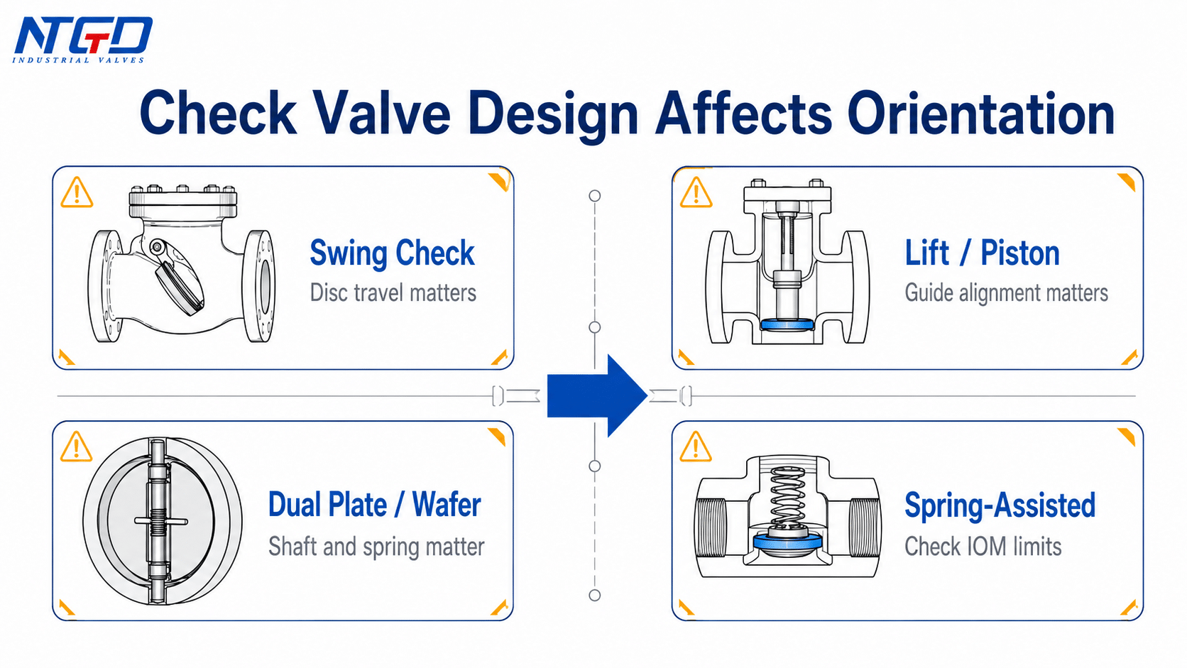
Not all check valves use the same internal closure arrangement. This is why a general statement such as “a check valve can be installed vertically” or “a check valve can be installed in any position” is too broad.
The flow direction may be marked clearly on the body, but installation orientation still depends on the internal design.
| Valve design | Direction concern | Orientation concern | Must verify |
|---|---|---|---|
| Swing check valve | Flow must push the disc or flapper away from the seat | Hinge position, disc travel, and gravity can affect closing reliability | Body arrow, hinge orientation, manufacturer guidance |
| Lift check valve | Flow must lift the disc or piston from the seat | Guide alignment and vertical / horizontal arrangement affect movement | Flow direction, guide design, vertical flow allowance |
| Ball check valve | Flow must move the ball away from the seat | Ball movement and gravity may affect response | Seat side, ball travel path, allowed orientation |
| Piston check valve | Flow must move the piston in the designed opening direction | Guide alignment and pressure differential matter | Inlet / outlet, piston guide, installation position |
| Wafer / dual-plate check valve | Flow must open both plates in the intended direction | Plate spring, shaft position, and closing response affect performance | Arrow, shaft orientation, spring-assisted design |
| Spring-assisted check valve | Flow must overcome spring force and open the closure element | Some designs may allow more orientation flexibility, but not universally | Spring arrangement, cracking behavior, manufacturer IOM |
| Stop check valve | Direction may depend on body design and under-disc flow path | Operation combines check function and stop function | Specific product drawing and IOM; detailed flow-path rules should remain with the product documentation |
| Y-pattern check valve | Body shape and internal flow path may not be obvious from exterior shape alone | Orientation and inlet / outlet should be checked carefully | Body arrow, tag, product drawing, and specific IOM |
Swing check valves
In a swing check valve, forward flow pushes a hinged disc or flapper away from the seat. When flow stops or reverses, the disc returns toward the seat. Because the hinge and disc movement are important, orientation should be confirmed against the manufacturer’s guidance instead of inferred from the body shape alone.
For swing-type designs, use the dedicated swing check valve page when hinge position, disc travel or vertical installation suitability needs more specific review.
The following NTGD swing check valve video can be used as a real product reference for hinged-disc check valve design. It should be viewed as a product example, not as a universal installation rule for every check valve type.
Lift, ball and piston check valves
Lift, ball, and piston check valves depend on guided movement of the closure element. Flow direction must allow the closure element to move away from the seat. These designs can be sensitive to guide alignment, gravity, pressure differential, and whether the line is horizontal or vertical.
Wafer, dual-plate and spring-assisted check valves
Wafer and dual-plate check valves often use plates, shafts, springs, or compact closure elements. Spring-assisted designs may close faster and may sometimes offer more flexibility in orientation, but this does not mean every spring check valve can be installed in any direction or position.
For pump-discharge or non-slam applications, NTGD’s spring-loaded check valve guide can help separate general flow-direction judgment from spring-assisted closing and cracking-pressure selection.
Why type-specific rules should not be generalized
A correct rule for one check valve type can be wrong for another. For example, a swing check valve, lift check valve, spring-assisted check valve, and stop check valve may all prevent reverse flow, but they do not necessarily share the same installation limits.
For this reason, the safest approach is:
- read the body arrow;
- confirm inlet and outlet;
- check the valve type;
- confirm the installation orientation;
- verify against the manufacturer IOM when service or orientation is critical.
Generalizing a vertical-installation rule from one check valve design to another can lead to unreliable closing, commissioning delay, or field rework.
For detailed flow direction and orientation rules for specific designs such as stop check valves, Y-pattern check valves, swing check valves, and spring-loaded check valves, use the dedicated product documentation for each valve type. This article provides the general field-check logic, not a substitute for type-specific instructions.
Check Valve Installation Direction and Orientation
Check valve installation direction is the direction in which the valve is installed relative to the intended pipeline flow. Orientation is the physical position of the valve body and closure mechanism, such as horizontal, vertical upward flow, or vertical downward flow.
Direction and orientation are related, but they are not the same thing. A valve can point in the correct flow direction but still be installed in an orientation that is not suitable for its design.
As a general rule, horizontal installation is compatible with many check valve designs, while vertical installation, especially vertical downward flow, requires explicit confirmation for the specific valve type, closure mechanism, and service condition.
Horizontal installation
Horizontal installation is common for many industrial check valves, but it still requires verification. The flow arrow should match the pipeline flow direction. For swing check valves, hinge position and disc movement should be checked. For lift, piston, ball, wafer, and spring-assisted designs, internal movement and manufacturer guidance should be reviewed.
Vertical upward flow
Vertical upward flow means the medium flows from bottom to top through the valve. Some check valves can be used in this orientation if the closure element can open under forward flow and close properly when flow stops. Suitability is determined by closure mechanism, size, spring arrangement, guide design, and service condition.
Vertical downward flow
Vertical downward flow means the medium flows from top to bottom. This orientation may be more restrictive for some check valve designs because gravity, disc travel, and closing response may not support reliable operation. It should be confirmed carefully before installation.
Direction, orientation and placement are not the same thing
A check valve may have three separate installation questions:
| Question | What it means | Example of what to check |
|---|---|---|
| Flow direction | Which way the medium should pass through the valve body | Body arrow, IN / OUT marking, inlet and outlet |
| Orientation | How the valve is positioned relative to gravity | Horizontal line, vertical upward flow, vertical downward flow |
| Placement | Where the valve is located in the system | Pump discharge, equipment protection point, process line location |
| Valve type suitability | Whether the selected check valve design fits that orientation | Swing, lift, piston, ball, dual-plate, spring-assisted design |
| Documentation confirmation | Whether the installation matches project and manufacturer requirements | IOM, drawing, tag, datasheet, valve list |
Placement decisions require the piping layout and the equipment protection point, not only valve size and valve type. For RFQ or technical review, provide the line drawing or installation position when flow direction or orientation is important.
Orientation matrix
| Installation orientation | Typical use | Main concern | What to check before installation |
|---|---|---|---|
| Horizontal flow | Common in many process lines | Closure element must open and close freely | Body arrow, hinge / guide position, pipe support, IOM |
| Vertical upward flow | May be acceptable for some designs | Forward flow must lift or open the closure element reliably | Valve type, spring or guide design, manufacturer allowance |
| Vertical downward flow | More restrictive for many designs | Closure element may not return to the seat reliably when flow stops, leaving the valve partially open during reverse-flow conditions | Specific IOM, service condition, closing behavior |
| Inclined line | Depends strongly on valve design | Closure movement may be unstable if the angle is not suitable | Manufacturer guidance and project specification |
| Unclear orientation | High risk before commissioning | Installer may confuse direction, position, and placement | Stop and verify drawing, tag, arrow, and IOM |
What Happens If a Check Valve Is Installed Backwards?
A check valve installed backwards may not behave like a normal valve installed in reverse. Because the internal closure element is designed for one-way operation, reversed installation can create operational and protection problems.
No flow or restricted opening
The most direct problem is that the valve may not open. If the forward process flow pushes the disc, plate, ball, piston, or poppet against the seat instead of away from it, the valve may block or restrict the line.
This can look like a pump problem, a blocked pipe, a closed manual valve, or an undersized valve. Before changing equipment, the flow arrow and installation direction should be checked.
Pressure buildup, abnormal pressure drop and noise
If the valve is installed in the wrong direction, upstream pressure may rise while downstream flow remains low. The system may show abnormal pressure drop, unstable noise, vibration, or repeated opening and closing.
However, direction is not the only possible cause of abnormal performance. High pressure drop can also come from incorrect sizing, debris, fouling, seat damage, insufficient flow to open the valve, or unsuitable cracking pressure. Direction should be checked first, but the investigation should not stop there if the direction is correct.
Backflow protection failure, water hammer and equipment risk
The purpose of a check valve is to help prevent reverse flow. If the valve is reversed or installed in an unsuitable orientation, it may fail to provide the intended backflow protection.
Wrong-flow installation can contribute to:
- reverse flow into equipment;
- pump or compressor protection failure;
- water hammer risk during sudden flow reversal;
- unstable closure behavior;
- seat or disc damage;
- commissioning delays and rework.
In high-pressure, pump discharge, steam, or other critical services, reversed installation can move beyond simple flow restriction and may contribute to accelerated equipment wear, unplanned shutdown, or elevated safety risk. The exact risk depends on the system, media, pressure, flow rate, valve design, and closing response.
Direction correct but still abnormal: other causes to check
If the arrow direction is correct but the system still has abnormal pressure drop, noise, no flow, or vibration, check for other causes:
| Symptom | Possible cause | System risk | What to check first |
|---|---|---|---|
| No downstream flow | Valve installed backwards, closure element stuck, blocked line | No process flow or equipment starvation | Arrow direction, valve opening movement, line blockage |
| High upstream pressure | Reversed valve, undersized valve, debris, fouling | Pressure buildup or pump overload risk | Direction, strainer condition, valve sizing |
| Chatter or vibration | Low flow, oversized valve, unstable closing, poor orientation | Wear, noise, unstable system operation | Flow rate, valve type, orientation, spring or disc movement |
| Reverse flow remains | Unsuitable check valve type, damaged seat, weak closure response, or debris on the seat | Backflow into protected equipment | Re-verify body arrow against process flow direction, then check seat condition and closure element |
| Water hammer risk | Delayed closure, reverse flow, unsuitable valve type | Pressure surge and equipment stress | Valve type, closing response, system transient conditions |
| Unexpected pressure drop | Direction correct but sizing or internal restriction unsuitable | Energy loss or reduced system performance | Cv / Kv data, bore, debris, operating flow |
Even when direction is correct, commissioning still requires a multi-factor fit-check, including valve sizing, minimum flow, debris, seat condition, cracking pressure, and service condition.
How to Confirm Flow Direction Before Tightening or Commissioning
A check valve should be direction-verified before final tightening, welding completion, insulation, or commissioning. Once installed, correcting a reversed valve may require shutdown, disassembly, lifting, rework, and schedule delay.
No-arrow verification checklist
If the valve has no visible arrow, the direction should be confirmed through documentation and safe inspection, not by guessing.
Never disassemble a pressurized valve to check internal direction.
For maintenance work where stored energy may be present, OSHA lockout/tagout guidance provides the general safety framework for controlling hazardous energy before servicing equipment.
Internal inspection should only be performed by qualified personnel after the line is fully isolated, depressurized, drained, and made safe according to site procedures.
| Check item | Why it matters | Who should confirm |
|---|---|---|
| Valve body arrow or FLOW marking | Fastest field-level direction reference | Installer / site engineer |
| IN / OUT marking | Confirms inlet and outlet side when arrow is absent | Installer / QA inspector |
| Valve tag | Confirms the valve belongs to the correct line | QA / project engineer |
| Line list or valve list | Confirms service, size, rating, and tag assignment | Project engineer |
| Manufacturer drawing | Shows inlet, outlet, and internal construction | Engineering / manufacturer |
| Manufacturer IOM | Confirms allowed orientation and installation cautions | Engineering / manufacturer |
| Internal closure direction | Helps confirm whether flow will open the valve; safe visual inspection may support the check only after isolation and depressurization | Qualified personnel, with final approval by engineering / manufacturer |
| Project specification | Confirms service-specific requirements | Project engineer / owner representative |
Drawing, tag, valve list and IOM review
Field markings should be checked against project documents. A valve may look similar to another valve in the same shipment, but a different internal design, material, pressure class, or flow direction can make it unsuitable for the intended line.
When documentation is available, the preferred confirmation sequence is:
- confirm the line flow direction on the project drawing;
- confirm the valve tag and line list;
- inspect the body arrow or IN / OUT marking;
- confirm the valve design and orientation limits in the IOM;
- verify final installed orientation before tightening or commissioning.
RFQ and specification information to provide
For a new check valve order or installation review, the valve manufacturer should receive enough information to confirm direction and orientation. At minimum, provide the service media, pressure and temperature range, flow direction, installation orientation, valve type preference, and any project drawing or tag information.
| Specification input | Why it matters for flow direction / orientation |
|---|---|
| Media | Affects material, seat, closing behavior, debris risk, and service suitability |
| Pressure and temperature | Affects valve class, body material, seat material, and design margin |
| Flow rate | Helps check whether the valve can open and operate stably |
| Intended flow direction | Confirms inlet and outlet arrangement |
| Horizontal or vertical installation | Determines whether the selected design is suitable |
| Vertical upward or downward flow | Critical for many closure designs |
| Valve type | Swing, lift, piston, ball, dual-plate, spring-assisted, or other design |
| End connection and pipe layout | Helps confirm physical installation feasibility |
| Drawing, tag, or line list | Helps prevent wrong valve placement or reversed installation |
| Special service condition | Corrosive, dirty, viscous, high-cycle, pump discharge, or transient flow conditions |
FAQ About Check Valve Flow Direction
Which way does a check valve go?
A check valve normally goes in the direction of the arrow on the valve body. The arrow should point from the inlet side toward the outlet side, matching the intended forward flow direction in the pipeline.
What direction should the check valve arrow point?
The check valve arrow should point in the direction of intended process flow. If the flow is from left to right, the body arrow should normally point from left to right. If the arrow is unclear or conflicts with the drawing, verify the manufacturer IOM, valve tag, and project documents before installation.
Can a check valve be installed vertically?
Some check valves can be installed vertically, but not all designs are suitable for every vertical orientation. Vertical upward flow and vertical downward flow should be checked separately.
Spring-assisted and dual-plate designs may offer more vertical flexibility than standard swing check valves in some services, while vertical downward flow usually requires stricter confirmation. The final authority is the manufacturer documentation for the specific valve design.
What happens if a check valve is installed backwards?
If a check valve is installed backwards, it may not open properly, may restrict or block flow, and may fail to provide backflow protection. The system may show high upstream pressure, no downstream flow, abnormal pressure drop, noise, vibration, or water hammer risk.
What if there is no arrow on the check valve?
In the field, arrows may be hidden by coating, insulation, corrosion, casting wear, or body position. If there is no visible arrow, do not guess. Check the IN / OUT marking, valve tag, line list, manufacturer drawing, datasheet, and IOM. If the direction is still unclear, confirm with the manufacturer or project engineer before tightening or commissioning.
Is the check valve symbol the same as the arrow on the valve body?
No. A P&ID or drawing symbol shows design intent on the drawing, while the body arrow shows the physical flow direction through the actual valve. Both should be consistent, but the drawing symbol does not replace field verification of the valve body marking, tag, internal construction, and installation orientation.
Can a check valve work in bidirectional flow?
A standard check valve is normally selected to allow flow in one direction and help prevent reverse flow. It is not normally used for free bidirectional flow unless a special design or system arrangement is specified. If bidirectional flow is required, a standard check valve is usually not the correct solution; the valve type and piping arrangement should be reviewed with engineering or the manufacturer.
Why is there pressure drop even when the direction is correct?
Pressure drop can still occur when the direction is correct. Possible causes include valve sizing, bore restriction, flow rate, media density, viscosity, debris, fouling, seat damage, low flow that does not fully open the closure element, or an unsuitable valve type for the service. First verify direction, then review sizing, debris, operating flow, and service conditions. This is a sizing and service-condition review, not only a flow-direction issue.
Conclusion
Correct check valve flow direction is confirmed by the body arrow, project documentation, and valve type — not by guesswork or drawing symbols alone.
The valve body arrow, FLOW marking, or IN / OUT marking normally shows the intended direction from inlet to outlet. That direction must also match the project drawing, valve tag, line list, and manufacturer documentation.
A check valve installed in the wrong direction can cause no flow, restricted opening, abnormal pressure behavior, loss of backflow protection, water hammer risk, equipment stress, and rework. Even when the direction is correct, the valve type and orientation still matter. Swing, lift, ball, piston, wafer, dual-plate, spring-assisted, stop check, and Y-pattern check valves can have different installation requirements.
The practical rule is simple: read the arrow, confirm the inlet and outlet, check the valve type, verify orientation, and review the IOM before final installation.
Application and Specification Support
If the flow direction, orientation suitability, or installation position is uncertain, especially in critical service or pump-discharge applications, the valve manufacturer should review the application before installation.
For industrial check valve selection or installation review, NTGD Valve can support direction and orientation checks based on the service condition and project documents. When requesting technical review, provide the media, pressure, temperature, flow rate, flow direction, horizontal or vertical orientation, preferred check valve type, end connection, piping layout, and any available drawing or valve tag.
For product-family review, start from the NTGD check valve product family page, then confirm the final valve type against the project media, pressure, orientation and backflow-protection requirement.
This information helps confirm whether the selected check valve design is suitable for the intended installation direction, service condition, and backflow protection requirement.
