Author: NTGD Valve Engineering Team
Last Updated: March 27, 2026
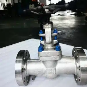
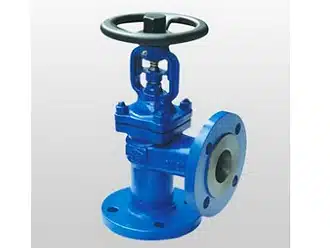
NTGD angle globe valve is an API-standard valve category and ASME B16.34 compliant 90-degree body pattern globe valve designed for pipeline directional change service that also requires dependable shut-off or controlled throttling. Compared with a standard globe valve installed together with an external 90° elbow, the angle pattern integrates the turn inside the valve body, simplifies piping layout, reduces external joints, and improves suitability for high-pressure, high-temperature, and pulsating-flow applications.
For buyers evaluating valves for steam lines, ammonia systems, feedwater duty, and other critical process service, this design solves three problems in one unit: it shuts off, regulates flow, and changes direction at the valve location. NTGD supports angle globe valve selection based on pressure class, temperature, medium compatibility, bonnet design, end connection, and project documentation requirements.
Quick Specifications
| Item | Range |
|---|---|
| Size Range | 1/2″–24″ (DN15–DN600) |
| Pressure Class | Class 150–2500 (PN10–PN420) |
| Design Standard | API 600 / ASME B16.34 |
| Main Service | Shut-off and throttling |
| Typical Media | Steam, ammonia, oil, hot water, process fluids |
| Typical End Connection | RF / RTJ Flanged, Butt Weld, Socket Weld |
Why Engineers Choose Angle Globe Valves
An angle globe valve is selected when one component must do three jobs at the same time: shut off the line, regulate flow, and change piping direction. In industrial systems, that translates into practical engineering value rather than just a different body shape.
Lower Installed Complexity
Because the 90° turn is built into the valve body, the installed arrangement can be simpler than a straight-pattern globe valve used together with a separate elbow. This can reduce the number of external joints, simplify fabrication, and make the piping layout more compact.
Reduced Leakage Risk
Every additional flange, weld, or threaded joint introduces another potential leak path. In steam, hot oil, ammonia, and other demanding service, reducing external connection points matters for both safety and maintenance.
Better Fit for Regulating Duty
Unlike valves mainly selected for full open / full close service, angle globe valves retain the throttling capability of a globe valve. That makes them suitable where stable modulation or controlled flow reduction is required.
Better Use of Tight Installation Space
In skids, utility corners, process modules, and compact piping runs, the angle body pattern can help achieve directional change without extending the layout with separate fittings.
Suitable for High-Pressure and Pulsating Service
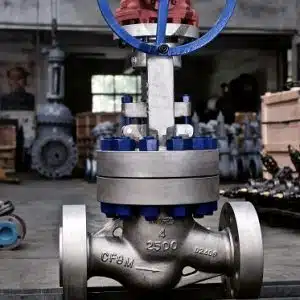
Angle globe valves are commonly selected for applications such as high-pressure steam lines, fertilizer plants, and feedwater systems where the valve must combine shut-off reliability with the performance expectations of a high pressure globe valve.
As a manufacturer, NTGD treats the angle globe valve not as a generic catalog item, but as an engineered solution selected according to working pressure, temperature, medium, required leakage performance, and maintenance expectation.
What Is an Angle Globe Valve?
An angle globe valve is a globe valve with inlet and outlet ports arranged at a right angle. It uses a linear-motion disc or plug to regulate flow and shut off the medium, while changing direction inside the valve body.
In practical terms, it is often selected where a standard globe valve would otherwise need an external elbow. The angle design combines directional change and globe-valve throttling performance in one assembly.
Structure and Flow Path
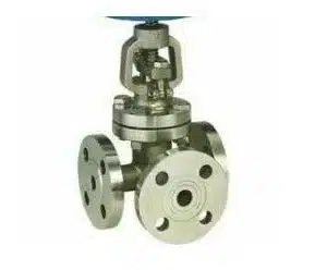
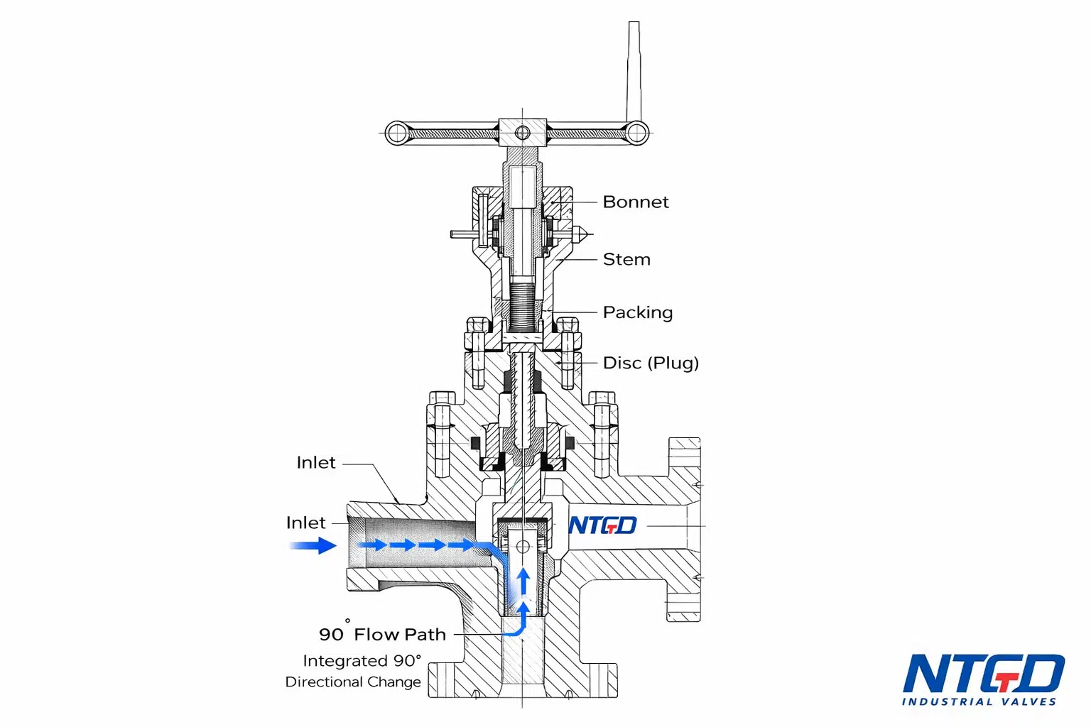
The internal structure of an angle globe valve follows the same basic operating principle as a standard globe valve, but the body geometry is different. The valve body forms a 90° flow path so the medium enters from one side and exits through a perpendicular outlet.
Main Components
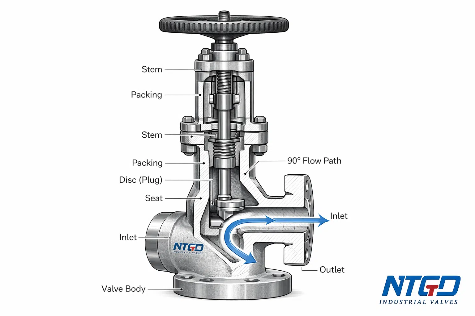
- Body
The pressure-retaining shell of the valve. In an angle globe valve, the body also forms the internal right-angle flow passage. - Seat
The sealing surface against which the disc closes. - Disc or Plug
The moving closure element that regulates flow or stops it completely. - Stem
Transfers motion from the handwheel or actuator to the disc. - Bonnet
Houses the stem assembly and provides access for maintenance. - Packing
Seals around the stem to prevent external leakage. - Handwheel or Actuator
Provides manual or automated operation.
Because the directional change happens inside the valve body, the internal flow path becomes a core part of the valve’s engineering value, not just its geometry.
How an Angle Globe Valve Works
The working principle is based on linear disc movement.
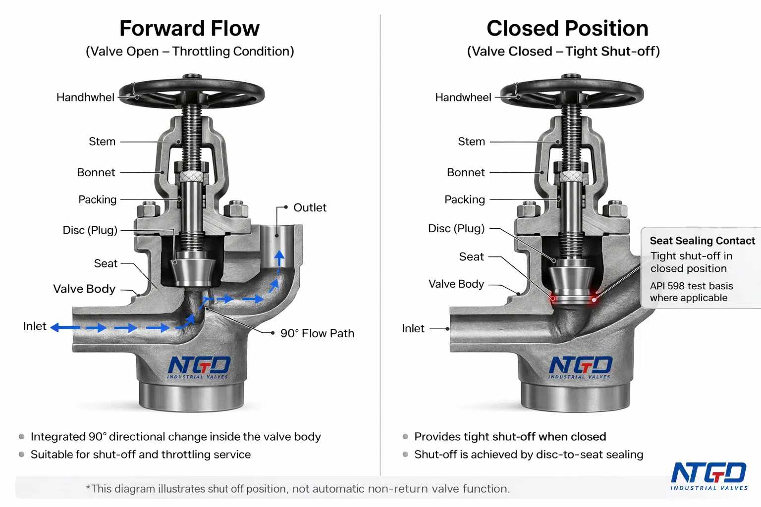
When the handwheel or actuator lifts the stem, the disc moves away from the seat and opens the passage. The medium enters the valve, turns through the 90° body pattern, and exits through the outlet. When the stem moves downward, the disc contacts the seat and shuts off the flow.
This operating principle allows the valve to perform two functions:
- Shut-off
The disc seals against the seat to stop the medium. - Throttling
The disc can be positioned between fully open and fully closed, allowing controlled flow regulation.
That is why angle globe valves are often selected in systems where shut-off alone is not enough and the valve must also provide usable control over flow rate.
Flow Characteristic for Precise Control
Unlike valves mainly used for on-off isolation, an angle globe valve is inherently suitable for regulating service. Depending on the trim design, the valve can be configured for linear or other flow characteristics appropriate for controlled service. This makes the design useful in steam lines, feedwater systems, and process loops where more stable modulation is required, much like the throttling duty discussed in globe valves used in high-flow throttling systems.
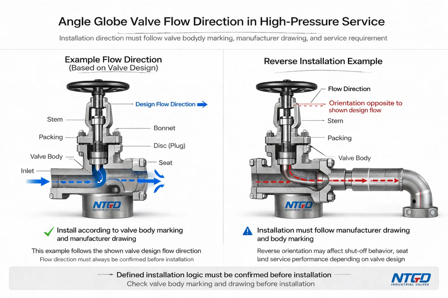
Flow Direction in High-Pressure Service
Angle globe valves have a defined flow direction, and correct installation should always follow the body marking, drawing, and service requirement. For certain high-temperature or high-pressure applications, installation logic may differ from general low-pressure service. That is why flow direction should always be confirmed against the actual valve design and project conditions before installation.
Key Advantages in Engineering Use
Integrated 90° Directional Change
The angle body pattern eliminates the need for a separate elbow at the valve location in many installations. This can simplify layout and reduce external connection complexity.
Practical Throttling Capability
Because the disc moves linearly relative to the seat, the valve is suitable for controlled regulation as well as shut-off. That gives it an advantage over many valves selected only for open-close duty.
Better Fit for High-Pressure Systems
Angle globe valves are widely used in high-pressure steam, ammonia, feedwater, and process service where sealing reliability and structural integrity matter.
Better Suitability for Pulsating Flow Conditions
In cyclic or pulsating service, the design can be preferred where flow direction change and shut-off must be managed in one robust component.
Service-Oriented Internal Design
For systems requiring inspection or seat/disc refurbishment, globe-type valves are often valued for their serviceability compared with some quarter-turn shut-off designs.
Technical Specifications
For industrial buyers, the usefulness of a product page depends on whether the core selection parameters can be reviewed quickly, especially when comparing different globe valve types. The table below provides the primary specification framework for angle globe valve evaluation.
| Item | Standard Range | Notes |
|---|---|---|
| Size Range | 1/2″–24″ (DN15–DN600) | Larger sizes subject to engineering confirmation |
| Pressure Class | Class 150–2500 | Equivalent PN range: PN10–PN420 |
| Flow Coefficient (Cv) | Available by size, trim, and travel | Required for control valve sizing and pressure drop review |
| Design Standard | API 600 / ASME B16.34 | Final basis to be confirmed by project requirement |
| Face-to-Face | As specified | Commonly reviewed against project dimensional standard |
| Flange / End Standard | RF / RTJ / Butt Weld / Socket Weld | Depends on size, class, and service duty |
| Testing Standard | API 598 | Additional inspection available on request |
| Seat Leakage Class | Standard industrial leakage requirement | Higher sealing requirement subject to design review |
| Body Material | Carbon Steel / Stainless Steel / Alloy Steel | Selected by medium, temperature, and pressure |
| Bonnet Design | Bolted Bonnet / Pressure Seal Bonnet | Depends on pressure class and duty |
| Operating Temperature | -40°C to 500°C | Subject to material and packing selection |
| Service Function | Shut-off / throttling | Final selection depends on operating conditions |
| Documentation | Datasheet / drawing / test report / MTR | Scope depends on order and project requirement |
Disc Design and Recommended Service
Instead of listing disc types without context, selection should be tied to actual service duty.
| Disc / Trim Type | Recommended Service |
|---|---|
| Plug Type Disc | Precision throttling, feedwater regulation, higher differential pressure control |
| Conventional or Ball Disc | General on-off duty and moderate throttling service |
| Composition Disc | Low-pressure service where softer sealing is required and media compatibility allows it |
Bonnet Design and Recommended Service
| Bonnet Type | Recommended Service |
|---|---|
| Bolted Bonnet | General Class 150–900 service where maintenance access is important |
| Pressure Seal Bonnet | Class 1500–2500 service where high pressure and temperature require more robust sealing logic, consistent with the sealing concept explained in this pressure seal valve primer. |
Stem and Disc Configuration
Stem and disc configuration should be selected according to operating duty, wear expectation, and maintenance requirement. Rising stem, lifting rotary stem, integral disc, and non-integral disc arrangements all exist, but they should be chosen by service condition rather than by catalog preference alone.
If your application requires throttling rather than only shut-off, specify desired flow rate and allowable pressure drop, because control valve sizing and Cv-based flow coefficient review are central to correct selection. NTGD can support Cv review and selection based on your working conditions.
Selection Support
Need help matching size, pressure class, material, and trim to your service conditions?
Send working pressure, temperature, medium, and connection requirement for engineering review.
Angle Globe Valve Selection Guide
Selecting an angle globe valve should be based on service condition, not just valve name.
Pressure and Temperature
Start with operating pressure and temperature. These determine the required pressure class, material grade, bonnet design, packing arrangement, and sealing logic.
For high-pressure service such as ammonia synthesis or high-pressure steam, bonnet design and pressure class should be reviewed carefully rather than selected only by nominal size.
Need help selecting the right pressure class and bonnet design? Send your operating pressure and temperature for review.
Medium Characteristics
The medium directly affects body material, seat design, trim selection, and packing arrangement. Buyers should confirm whether the medium is:
- steam
- hot oil
- water
- fuel oil
- ammonia
- corrosive process fluid
- hazardous or toxic fluid
- fluid containing solids
Material suitability should always be checked against real service duty, not assumed from general valve category.
Need help with material selection? Share medium composition and service temperature with our engineering team.
Shut-off Only or Flow Regulation
If the valve will be used for throttling rather than only isolation, disc type, travel range, and allowable pressure drop become more important. This is also where Cv review becomes necessary.
Need throttling support? Send required flow rate and pressure drop range for selection assistance.
Installation Layout
The angle pattern is most useful when the valve is installed at a point where the pipeline changes direction. In space-constrained piping, this can simplify routing and reduce dependence on external elbows.
Need drawing review? NTGD can assess whether the angle pattern is the better choice for your piping layout.
Connection Standard
Connection compatibility should be confirmed against project requirements, including flange type, weld end specification, class rating, and dimensional compatibility.
Need quote support? Provide line size, connection standard, and required quantity.
Maintenance and Reliability
For systems requiring periodic inspection, more service-friendly trim access, or higher sealing confidence, maintenance expectation should be considered during selection.
Need documentation support? Datasheets, drawings, material traceability, and test records can be reviewed at inquiry stage.
Typical Applications
Angle globe valves should be selected by working condition, not by appearance alone. The following applications show where the design is most relevant.
Steam Systems
Core issue: high temperature, pressure fluctuation, and repeated throttling duty.
Why angle globe valve fits: the valve combines shut-off and regulated flow control in one body pattern while reducing the need for an external elbow in corner installations.
Typical value: suitable for steam lines where sealing reliability and controllable flow matter more than simple on-off isolation, especially in applications similar to steam control systems.
In steam service, engineers often compare angle globe valves with steam globe valves when evaluating layout, pressure class, and throttling requirements.
Ammonia and Fertilizer Plants
Core issue: high pressure, cyclic flow, and high sealing expectations.
Why angle globe valve fits: the design can be used where the line changes direction and where the valve must also deliver dependable shut-off under demanding operating conditions.
Typical value: often selected in ammonia and fertilizer systems where Class 1500–2500 service, directional change, and maintenance reliability must be considered together.
For severe process duty, buyers also compare this product with high-pressure globe valve applications to confirm the best design basis for the line.
Boiler Feedwater Systems
Core issue: pressure variation, thermal stress, and the need for stable regulation.
Why angle globe valve fits: linear-motion trim makes the valve more suitable than many on-off valves for controlled feedwater service.
Typical value: useful where the valve must combine shut-off with repeatable control.
Fuel Oil and Hot Oil Systems
Core issue: elevated temperature and the need for dependable shut-off with controllable flow.
Why angle globe valve fits: the globe-type trim supports regulated service while the angle body pattern can simplify piping at directional change points.
Typical value: suitable where temperature resistance and throttling performance are more important than quick quarter-turn operation.
Instrument Lines, Vents, and Drains
Core issue: compact installation space and the need for dependable sealing.
Why angle globe valve fits: the compact body pattern is useful in smaller service lines where flow direction change and shut-off are both required.
Typical value: practical for vents, drains, gauge lines, and similar smaller industrial service points.
Real Project Reference
For project procurement, buyers often request evidence of comparable service experience, especially in steam and fertilizer applications. Where project confidentiality permits, NTGD can support technical review with documentation, drawings, and reference-based discussion matched to pressure class, medium, and service duty.
Angle Globe Valve Compared with Other Valve Types
When buyers search for an angle globe valve, they are often comparing it not only with a standard globe valve, but also with ball valves or gate valves, and the basic design logic is close to the overview in this globe valve technical primer. The table below makes the engineering differences easier to review.
| Feature | Angle Globe Valve | Standard Globe Valve | Ball Valve | Gate Valve |
|---|---|---|---|---|
| Flow Path | 90° internal turn | Straight pattern | Straight-through quarter-turn | Straight-through linear gate |
| External Elbow Requirement | Often reduced | Usually needed if line changes direction | Not intended for directional change | Not intended for directional change |
| Throttling Suitability | Good | Good | Limited for controlled regulation | Poor |
| Shut-off Service | Good | Good | Good | Good |
| Compact Corner Installation | Better | Less efficient if elbow required | Depends on piping arrangement | Depends on piping arrangement |
| Typical Use Case | Shut-off + throttling + directional change | Shut-off + throttling in straight line | Fast on-off isolation | Full open / full close isolation |
For buyers comparing body pattern and throttling logic, a standard industrial globe valve remains the closest reference. For higher pressure projects, high pressure globe valves are often reviewed in parallel.
Installation and Maintenance Considerations
Installation
Angle globe valves should be installed according to body marking, flow direction, service duty, and project specification. Before installation, confirm:
- flow direction marking
- pressure side arrangement
- connection compatibility
- handwheel or actuator orientation
- maintenance accessibility
For high-pressure and high-temperature service, installation direction should be reviewed against the actual valve design rather than assumed from general low-pressure practice.
Maintenance
One practical advantage of globe-type valves is that seat and disc areas are comparatively service-oriented. Maintenance planning should include:
- checking stem packing condition
- inspecting seat and disc wear
- verifying sealing performance
- reviewing actuator or handwheel operation
- confirming bonnet integrity after service cycles
For frequent-regulation service, operating condition and trim wear should also be reviewed periodically.
Compliance and Engineering Documentation
For industrial buyers, a useful angle globe valve page must show not only what the product is, but also how it aligns with project compliance requirements.
NTGD angle globe valves are reviewed against project requirements covering design basis, material selection, testing, traceability, and documentation scope.
Core Compliance Standards
- Design and Manufacturing: API 600 / ASME B16.34
- End Connection / Flange Review: according to specified project standard
- Testing and Inspection: API 598 valve inspection and testing.
- Material Traceability: available per order or project requirement
- Quality Documentation: datasheet, drawing, test report, and material record as required
Projects requiring broader product family review may also compare with API 600 industrial valves.
Typical Pre-Shipment Review Scope
Depending on order requirements, review and documentation may include:
- technical datasheet
- general arrangement drawing
- material information
- inspection record
- hydrostatic and seat test report
- material traceability documentation
- quotation with specification review
If your project has specific documentation, inspection, or certification requirements, these should be defined at inquiry stage so the scope can match procurement expectations.
FAQ
What is an angle globe valve?
An angle globe valve is a globe valve with inlet and outlet arranged at a 90-degree angle. It changes direction inside the body while providing shut-off and throttling capability.
What is an angle globe valve used for?
It is used in industrial piping where flow direction changes at the valve location and where the valve must also provide dependable shut-off or regulated flow control. Typical services include steam, ammonia, feedwater, hot oil, and process lines.
What is the difference between angle globe valve and standard globe valve?
The main difference is body pattern. A standard globe valve is straight-pattern, while an angle globe valve integrates a right-angle turn inside the body. That can reduce the need for an external elbow in some installations.
Can an angle globe valve be used for throttling?
Yes. Because the disc moves linearly relative to the seat, angle globe valves are commonly used in service where throttling or controlled flow reduction is required.
What pressure class is available for angle globe valves?
Typical industrial angle globe valves are supplied from Class 150 up to Class 2500, depending on design and application requirement.
What materials are used for angle globe valves?
Material selection depends on service condition. Common options include carbon steel, stainless steel, and alloy steel, chosen according to medium, temperature, and pressure requirement.
How do you select an angle globe valve for steam service?
Start with pressure class, operating temperature, body material, bonnet design, end connection, and whether the valve is required for shut-off only or also for throttling. Flow direction and installation logic should also be confirmed before installation.
Does an angle globe valve have a flow direction?
Yes. Flow direction must be confirmed according to the valve design, body marking, and service requirement before installation.
How do you calculate pressure drop across an angle globe valve?
Pressure drop is typically reviewed using flow rate, fluid condition, and Cv value. For regulated service, the correct approach is to evaluate required flow and allowable pressure drop together rather than using body size alone. NTGD can support Cv-based review for project selection.
Which flow direction is preferred for high-pressure steam service?
The preferred flow direction depends on actual valve design and service logic. For high-pressure steam service, the valve should always be installed according to the manufacturer’s drawing, body marking, and project requirement rather than a general rule taken from another valve type.
Still have questions? Ask Engineering Support for application-specific guidance.
Ready to Specify Your Angle Globe Valve?
An angle globe valve is not just a modified globe valve with a 90° body. It is an engineered solution that combines directional change, flow regulation, and dependable shut-off in one compact component. In critical service, that can mean simpler layout, fewer external joints, and better fit for demanding pressure and temperature conditions.
NTGD supports angle globe valve selection with technical data, specification review, and project-oriented documentation. If you are evaluating a valve for steam, ammonia, feedwater, fuel oil, or other process service, send the following information for a faster recommendation:
- line size
- pressure class or operating pressure
- operating temperature
- medium
- end connection
- manual or actuated operation requirement
- quantity required
NTGD angle globe valves are supplied with engineering review support, documentation according to order scope, and pre-shipment testing aligned with product requirements. For projects requiring API 600 / ASME B16.34 design basis, material traceability, and test documentation, we can align quotation support with your procurement process.