Author Name: Bruce Zheng
Author Role: Co-Founder and Valve Engineer at NTGD Valve
Author Bio: Bruce Zheng is Co-Founder and Valve Engineer at NTGD Valve, focusing on industrial valve selection, application, and technical content for global B2B buyers.
Last Updated: May 15, 2026
When engineers compare globe valve types, the real question is not only what the valve is called. The more important question is how each globe valve type affects flow path, pressure drop, throttling performance, leakage control, maintenance access, and service suitability.
In most industrial piping systems, globe valves are selected when the line needs flow regulation, throttling, or controlled shut-off rather than simple full-open / full-closed isolation. However, different types of globe valves solve different problems.
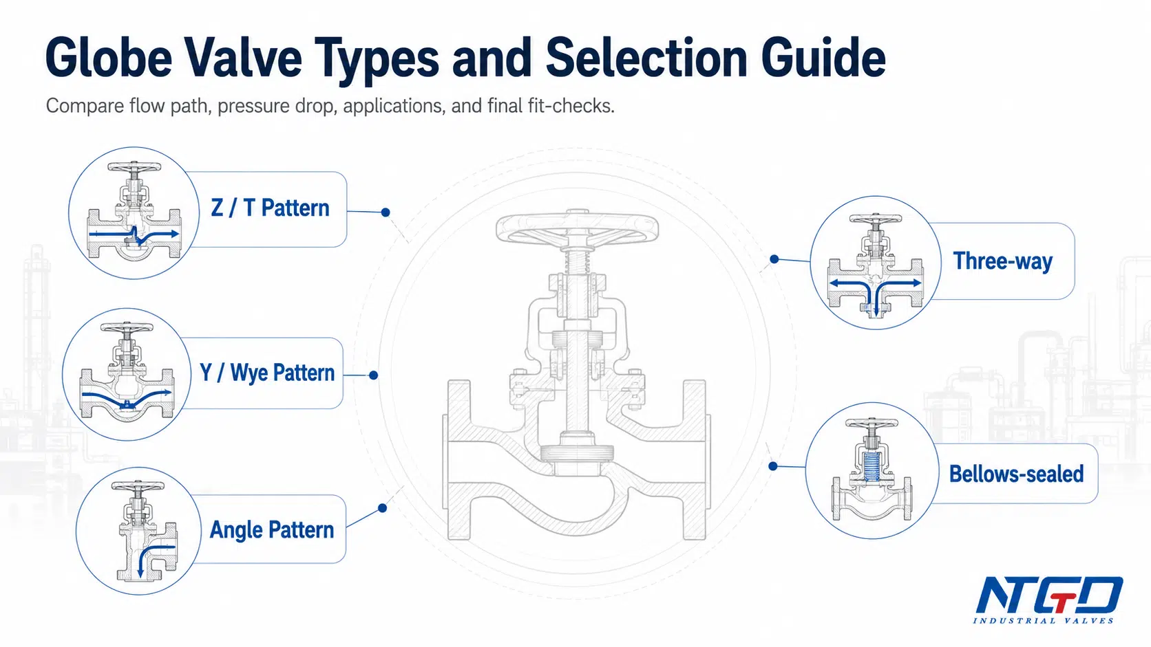
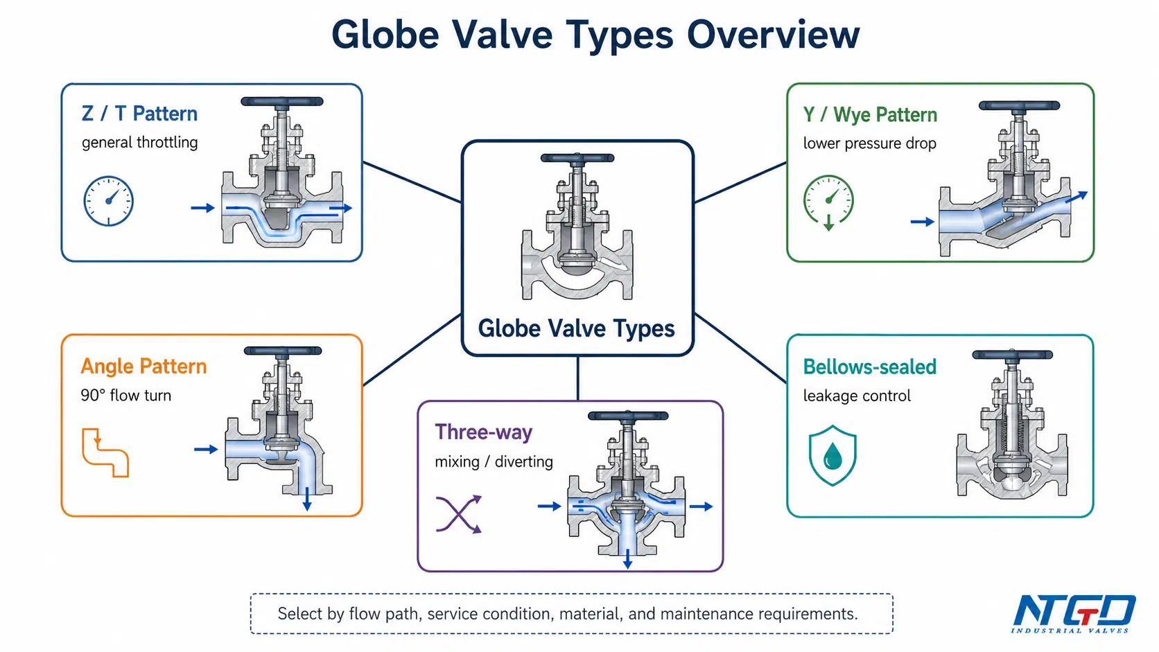
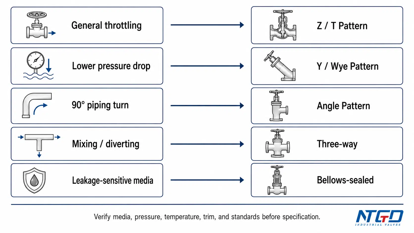
A Z-pattern globe valve is often used for general throttling where higher pressure drop is acceptable. A Y-pattern globe valve may be preferred when smoother flow and lower pressure loss are important. An angle-pattern globe valve helps when the pipeline requires a 90-degree flow turn. A three-way globe valve is selected for mixing or diverting flow. A bellows-sealed globe valve is used when stem leakage control is critical.
This guide explains how the main types of globe valves differ, how their parts affect selection, and how to match each type to media, pressure, temperature, flow direction, material, actuation, and application conditions. In this guide, Z-pattern, Y-pattern, and angle-pattern valves are treated as the main body-pattern categories, while three-way and bellows-sealed globe valves are treated as special configuration or special-service designs.
Key Takeaways: How to Compare Globe Valve Types
| Selection Point | Practical Meaning |
|---|---|
| Z-pattern, Y-pattern, and angle-pattern are the main globe valve body patterns. | Start with these three types when comparing internal flow path, pressure drop tendency, and piping layout. |
| Three-way and bellows-sealed globe valves are special-purpose types. | Use them when the service needs flow routing or leakage control, not simply because they appear in a list of globe valve types. |
| A Z-pattern globe valve is common, but pressure drop is usually higher. | Prefer it for general throttling when pressure loss is acceptable; reconsider it when low pressure drop is a strict requirement. |
| A Y-pattern globe valve provides a smoother flow path. | Consider it when the system needs globe valve control with reduced flow resistance; avoid overspecifying it where this benefit is not needed. |
| An angle-pattern globe valve changes flow direction by about 90 degrees. | Prefer it when flow control and pipe direction change are both required; reconsider it if the installation orientation creates drainage or maintenance issues. |
| Globe valve selection should not stop at the type name. | Media, trim, seat, material, pressure class, temperature, actuation, and maintenance access must also be checked. |
| Standards and ratings should be verified from project specifications and datasheets. | Do not assume pressure-temperature limits, leakage performance, Cv values, or standard compliance without supporting data. |
What Is a Globe Valve and Why Type Selection Matters
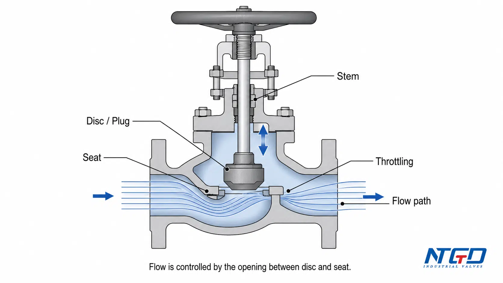
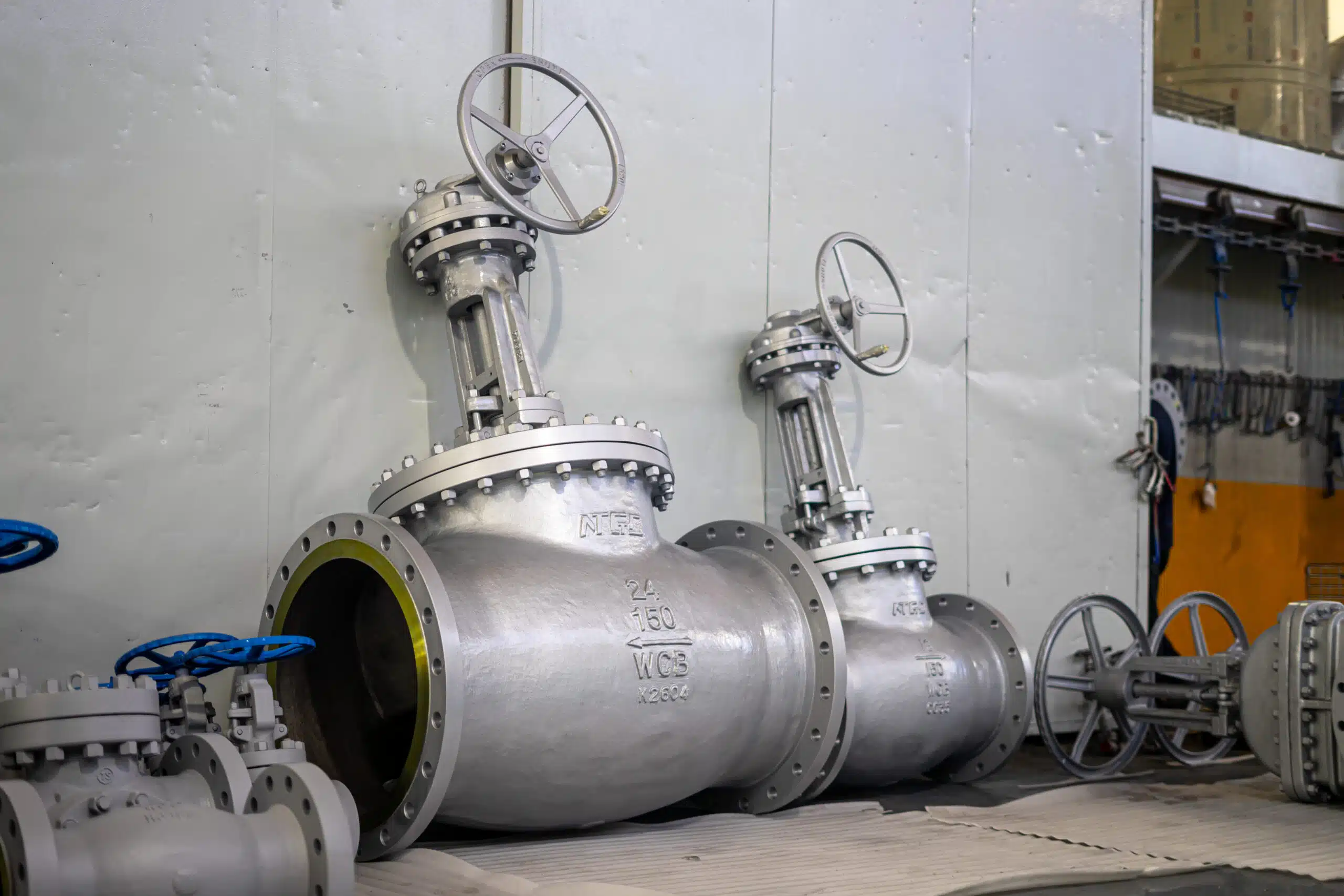
A globe valve is a linear-motion valve used to start, stop, and regulate flow. Inside the valve, a disc or plug moves toward or away from a seat. As the opening between the disc and seat changes, the valve controls the flow area and adjusts how much fluid passes through the pipeline.
This matches the common engineering description of a globe valve as a linear-motion valve used to stop, start, and regulate flow.
Unlike many straight-through valve designs, a globe valve normally forces the flow to change direction inside the body. This is one reason globe valves are useful for throttling, but it is also why they usually create more pressure drop than some isolation valve types.
For engineers and buyers, the type of globe valve matters because body geometry, flow path, sealing construction, and internal components directly affect system behavior.
A globe valve type can influence:
- throttling stability;
- pressure drop;
- flow direction requirements;
- seat and trim wear;
- shut-off performance;
- stem leakage risk;
- maintenance access;
- actuator selection;
- suitability for steam, water, oil, gas, chemical, or other process media.
A valve that matches the size and pressure class may still be wrong if its body pattern, material, trim, seat design, flow direction, or leakage-control method does not match the service conditions.
Basic Working Principle
A globe valve regulates flow by moving a disc or plug against a fixed seat. The stem transfers motion from a handwheel, gear operator, pneumatic actuator, or electric actuator to the disc or plug. The bonnet supports the stem and provides access to the internal parts.
The main working logic is simple:
- When the disc moves away from the seat, the flow area increases.
- When the disc moves toward the seat, the flow area decreases.
- When the disc contacts the seat, the valve closes.
- During partial opening, the valve can throttle flow.
This makes globe valves suitable for regulating service, but it also means the seat, disc, trim material, flow path, and actuator must be selected carefully.
Why Globe Valves Are Used for Flow Control
Globe valves are commonly used when controlled flow is more important than minimum flow resistance. They are often found in:
- cooling water lines;
- steam and condensate systems;
- boiler feedwater service;
- fuel oil systems;
- chemical processing;
- bypass and regulating lines;
- process control applications;
- services where shut-off and throttling are both required.
In these services, the throttling advantage of a globe valve may justify the additional pressure drop only when the body pattern, trim, material, and actuator are matched to the operating conditions. In chemical service, globe valves in chemical processing should be selected with extra attention to corrosion, leakage control, trim material, and maintenance exposure. If the body pattern is chosen poorly, the same throttling service can suffer from excessive pressure loss, unstable control, or unnecessary maintenance exposure.
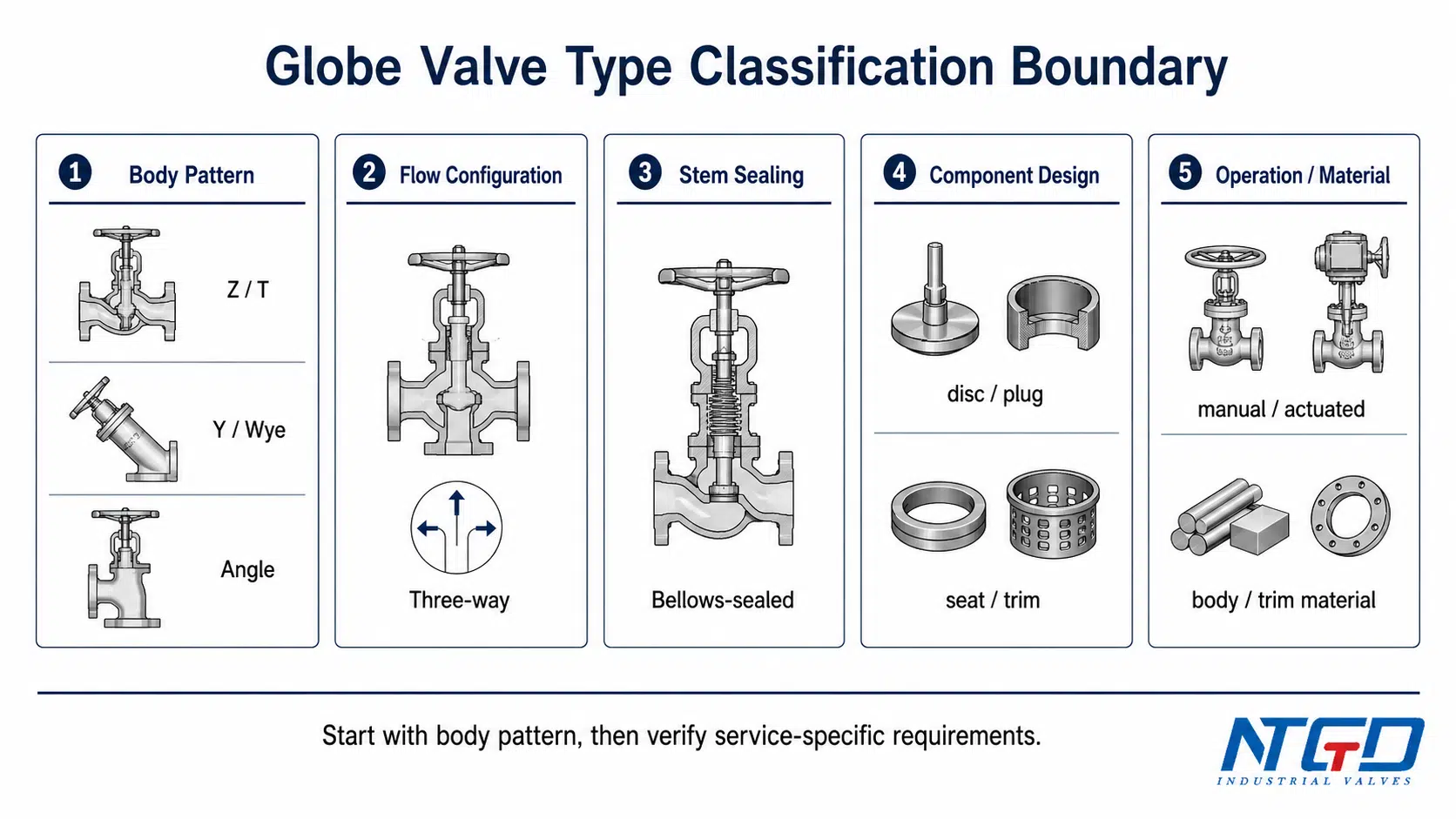
How Globe Valve Types Are Classified
The phrase types of globe valves can be confusing because globe valves can be classified in several different ways. Some classifications describe the body pattern. Others describe flow routing, stem sealing, disc design, bonnet construction, material, or actuation.
For practical selection, it is useful to separate these classification levels.
| Classification Basis | Common Examples | What It Mainly Affects | Selection Note |
|---|---|---|---|
| Body pattern | Z-pattern / T-pattern, Y-pattern / Wye pattern, angle-pattern | Flow path, pressure drop, piping layout | This is the primary layer for comparing most globe valve body types. |
| Flow configuration | Three-way globe valve | Mixing, diverting, flow routing | This is a special configuration, not the same selection level as Z / Y / angle body patterns. |
| Stem sealing design | Bellows-sealed globe valve | External leakage control | This is a special-service design for leakage-sensitive media, not a body-pattern alternative. |
| Disc / plug design | Plug disc, needle disc, soft seat, metal seat | Throttling behavior, shut-off, wear resistance | Important for performance, but usually not the first classification layer. |
| Bonnet design | Bolted bonnet, welded bonnet, pressure-seal bonnet | Maintenance access, pressure / temperature suitability | Must be checked against design conditions and manufacturer data. |
| Material / trim | Carbon steel, stainless steel, alloy, hard-faced trim | Corrosion, erosion, temperature, media compatibility | Must match the actual media and operating conditions. |
| Actuation | Manual, pneumatic, electric | Operation method and control requirements | Usually selected after body type and service conditions are defined. |
Body Pattern vs. Special Service vs. Component-Based Classification
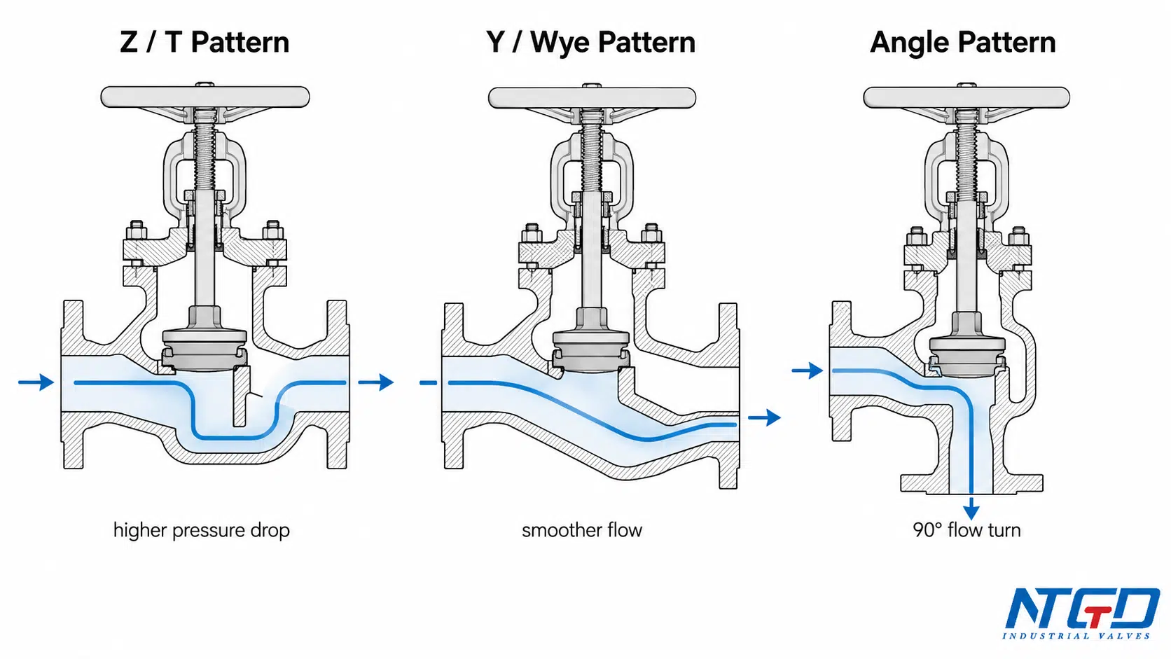
The most common globe valve body patterns are:
- Z-pattern / T-pattern globe valve
- Y-pattern / Wye pattern globe valve
- Angle-pattern globe valve
These body patterns mainly describe the internal flow route through the valve.
Other globe valve types describe different selection logic. A three-way globe valve describes a flow routing function. A bellows-sealed globe valve describes a stem sealing construction. A disc type, bonnet type, material type, or actuator type describes a secondary selection dimension.
Why Classification Boundaries Matter in Selection
Classification boundaries matter because different “types” answer different engineering questions.
A buyer asking about a Z-pattern globe valve is usually asking about body geometry and pressure drop. A buyer asking about a bellows-sealed globe valve is usually asking about external leakage control. A buyer asking about a three-way globe valve is usually asking about mixing or diverting flow.
If these categories are placed on the same level without explanation, selection becomes unclear. A better approach is to first identify the body pattern, then check whether the service also needs special flow routing, leakage control, material compatibility, or actuation. Confusing these levels can lead to a valve that has the right general name but misses the actual service requirement, such as leakage control, port routing, or allowable pressure drop.
Main Globe Valve Body Patterns
The three main body patterns are Z-pattern, Y-pattern, and angle-pattern; GlobalSpec also describes globe valves as available in three main body types, including angle, Y-shaped, and Z-shaped designs. These are the most important globe valve types for understanding flow path, pressure drop, and application fit.
Z-Pattern / T-Pattern Globe Valve
A Z-pattern globe valve, also called a T-pattern globe valve, Tee-pattern globe valve, or standard pattern globe valve, is one of the most common globe valve body designs.
In this design, the fluid changes direction as it passes through the valve body and across the seat. The internal flow path is often described as Z-shaped because the flow does not pass straight through the body.
This design provides stable throttling because the disc and seat are positioned to control flow effectively. The trade-off is higher pressure drop compared with smoother flow path designs.
A Z-pattern globe valve is commonly selected when:
- general throttling or flow regulation is required;
- the media is relatively clean;
- pressure drop is acceptable;
- the system needs a common and proven globe valve body pattern;
- top-entry access to internal parts is useful for maintenance.
A Z-pattern globe valve may need reconsideration when:
- the system has strict low pressure drop requirements;
- the service contains heavy solids or abrasive particles;
- high flow capacity with low resistance is more important than throttling;
- severe erosion may occur at the seat or trim;
- another body pattern can reduce pressure loss without sacrificing control.
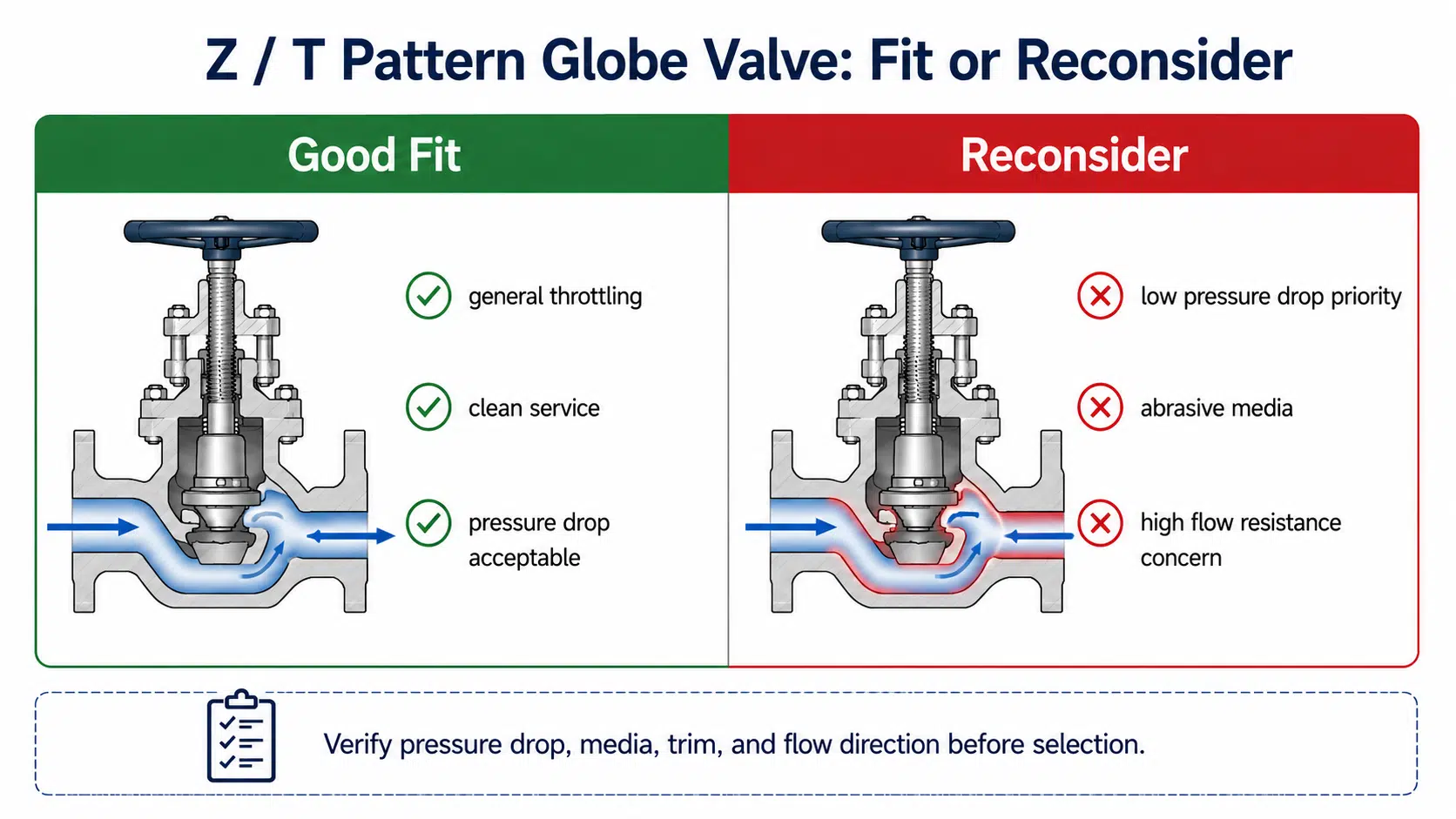
If a Z-pattern globe valve is used where low pressure drop is critical, the system may experience insufficient flow, higher pump load, or reduced process performance. In abrasive or high-velocity service, the more tortuous flow path can also accelerate seat and trim wear, which may reduce shut-off quality or throttling stability over time.
For many industrial users, the Z-pattern globe valve is the default reference when comparing globe valve types. It is widely used, but it should not be selected automatically without checking pressure drop, media, flow direction, and trim suitability.
Y-Pattern / Wye Pattern Globe Valve
A Y-pattern globe valve, also called a Wye pattern globe valve, uses an angled body arrangement to create a smoother flow path than a standard Z-pattern globe valve.
The main advantage of this design is reduced flow resistance. Because the flow path is less abrupt, a Y-pattern globe valve can reduce pressure drop in suitable applications while still providing globe valve throttling characteristics.
A Y-pattern globe valve is commonly considered when:
- pressure drop must be reduced compared with a Z-pattern design;
- the service has higher flow velocity or higher differential pressure;
- the line needs smoother flow through the valve body;
- throttling is required but the system cannot tolerate excessive pressure loss;
- the project requires globe valve control in a more demanding flow condition.
Final specification must verify:
- installation orientation;
- available maintenance space;
- pressure / temperature rating;
- body and trim material;
- flow direction;
- manufacturer instructions;
- compatibility with the full piping layout.
The selection question is not simply whether a Y-pattern globe valve is “better.” The real question is whether the smoother flow path solves the system’s pressure drop problem while still meeting control, rating, material, and maintenance requirements. If the service does not benefit from the lower-resistance flow path, a Y-pattern design may add cost or maintenance complexity without meaningful performance improvement.
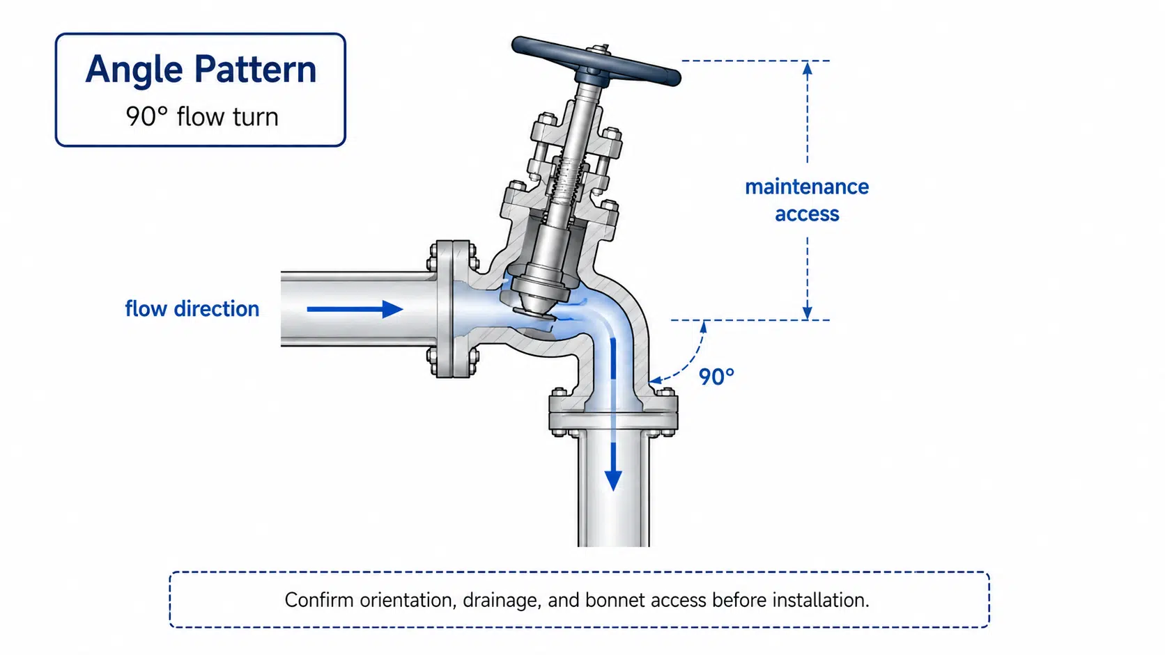
Angle-Pattern Globe Valve
An angle-pattern globe valve changes the flow direction by approximately 90 degrees inside the valve body. Instead of using a separate pipe elbow and a straight-pattern valve, an angle globe valve can sometimes combine direction change and flow control in one valve body.
Angle-pattern globe valves are commonly selected when:
- the pipeline already needs a 90-degree direction change;
- installation space is limited;
- the design can reduce one elbow or fitting;
- throttling or controlled shut-off is still required;
- maintenance access is acceptable in the installed orientation.
This type is useful when piping layout and flow control must be solved together. However, an angle-pattern globe valve should not be selected only for space saving. Critical verification includes:
- flow direction;
- pressure drop;
- orientation;
- drainage requirements;
- bonnet and packing access;
- body material;
- seat and trim suitability;
- manufacturer installation instructions.
An angle-pattern globe valve can simplify layout in the right service, but poor orientation or insufficient access can create maintenance and operating problems. If installed in an unsuitable direction or in dirty service without proper drainage, the body can retain media or solids, increasing the risk of local wear, blockage, or difficult cleaning.
Special Globe Valve Types and Service Designs
Some globe valve types are not defined mainly by the body pattern. They are selected because the process needs a special flow function or a special sealing design.
Three-Way Globe Valve
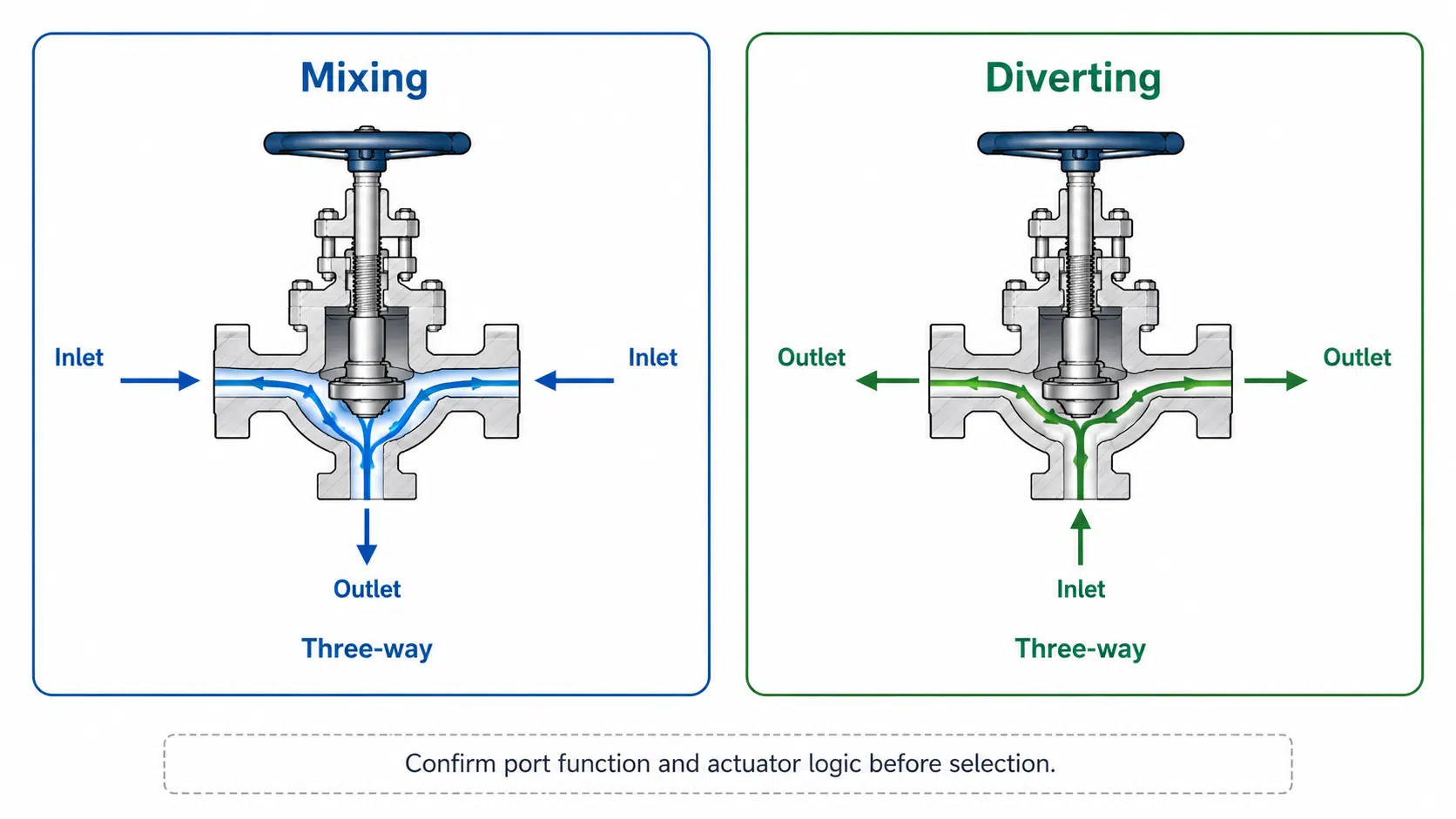
A three-way globe valve has three ports and is used for mixing, diverting, or routing flow. It is not simply another body pattern like Z-pattern, Y-pattern, or angle-pattern. Its selection logic is based on flow configuration.
A three-way globe valve may be used when:
- one flow stream must be divided into two directions;
- two streams must be mixed;
- the process needs flow changeover between lines;
- a control system requires routing flexibility;
- one valve can replace multiple separate flow-routing components.
Prior to specifying a three-way globe valve, the following design and operational factors must be evaluated:
- whether the valve is used for mixing or diverting;
- flow direction through each port;
- pressure balance between ports;
- actuator requirements;
- leakage expectations;
- control logic;
- maintenance access.
A three-way globe valve should only be selected when the system actually needs a three-port flow function. It should not be included in the same selection layer as Z / Y / angle body patterns without explaining this difference.
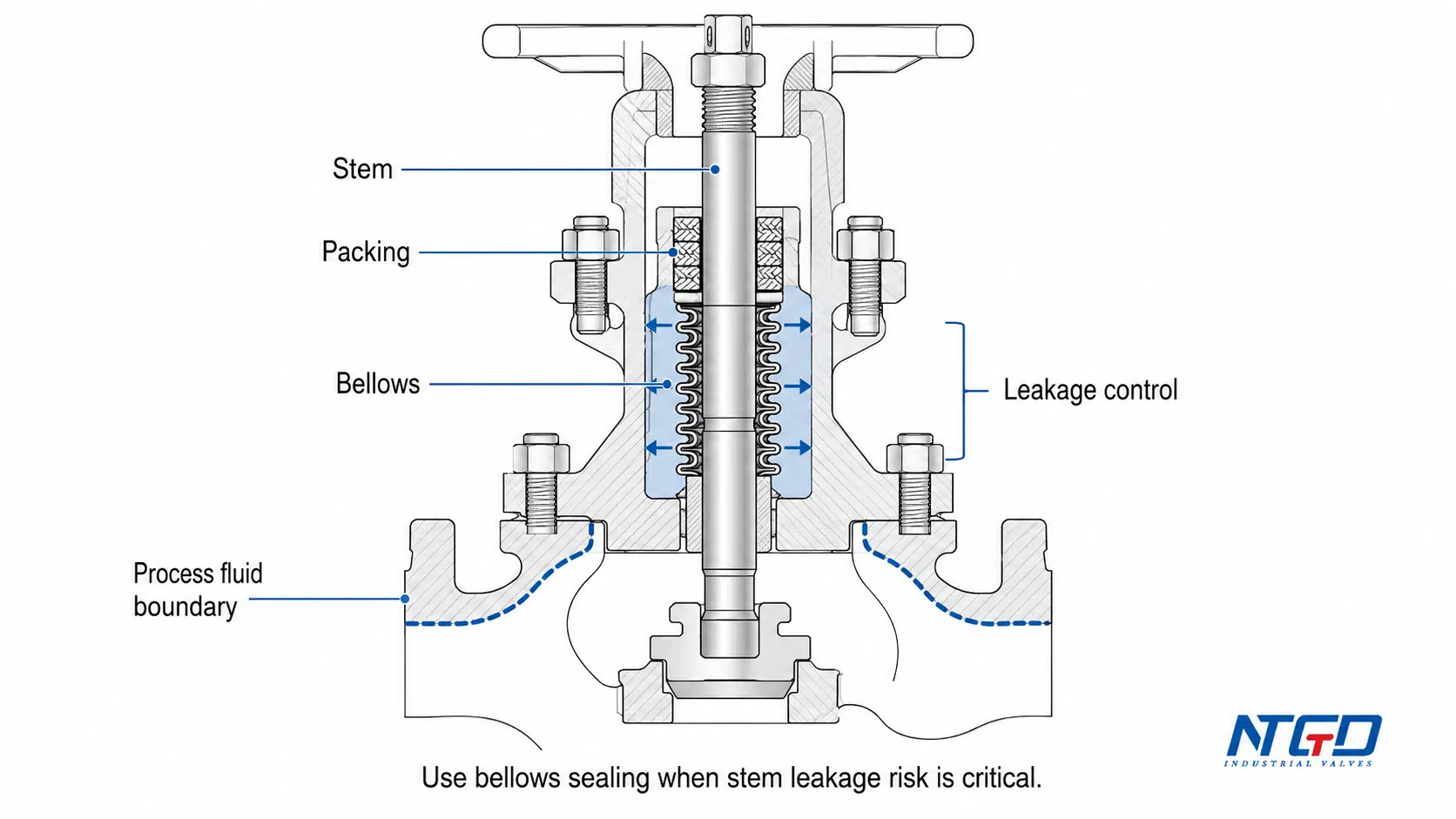
Bellows-Sealed Globe Valve
A bellows-sealed globe valve is selected when external leakage through the stem area must be minimized. In this design, a metal bellows assembly helps isolate the process fluid from the atmosphere.
This type is commonly considered for:
- toxic media;
- volatile fluids;
- hazardous fluids;
- heat transfer oil;
- vacuum or leakage-sensitive service;
- expensive or high-value media;
- processes where fugitive emissions must be controlled.
The main selection logic is stem leakage control, not body flow path. A bellows-sealed valve may still use a body pattern such as Z-pattern or angle-pattern, but the bellows feature answers a different question: how to reduce leakage at the stem area.
When selecting a bellows-sealed globe valve, final specification must verify:
- bellows material compatibility;
- pressure and temperature limits;
- cycle expectations;
- backup packing arrangement;
- maintenance method;
- media hazard level;
- whether the service truly requires bellows sealing.
A bellows-sealed design can improve leakage control in the right application, but it also adds complexity. It should be matched to the service risk instead of treated as a universal upgrade.
Other Secondary Type Dimensions to Confirm
After the main body pattern and special service needs are defined, other design dimensions may still affect final selection. These dimensions typically become important after the main body pattern and any special service requirement are clear, because they convert a general valve type into a complete technical specification. For compact high-pressure service, a forged steel globe valve may be reviewed when material strength, pressure class, and body construction are key requirements.
These include:
- disc or plug design;
- seat design;
- bonnet construction;
- packing type;
- trim material;
- body material;
- end connection;
- manual, pneumatic, or electric operation.
These details should not replace the main globe valve type classification, but they can determine whether the selected valve will actually perform correctly in service.
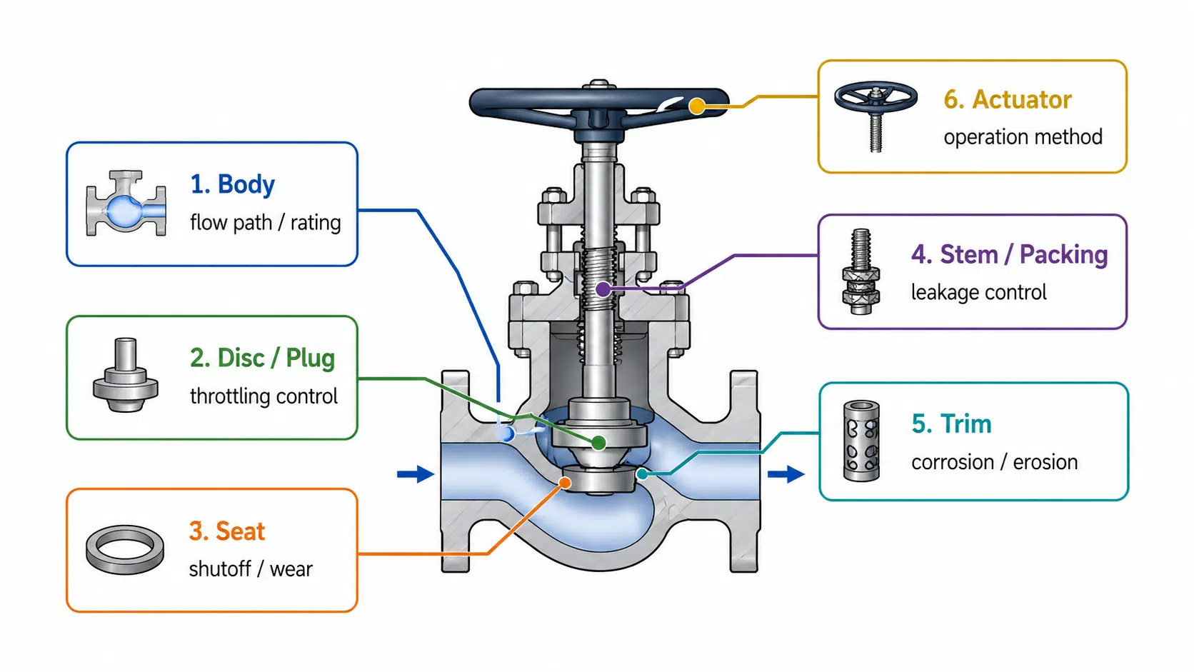
Globe Valve Parts and Components That Affect Selection
Globe valve parts are not only construction details. They directly affect throttling behavior, shut-off performance, leakage control, maintenance access, and service life.
The goal is not to turn this page into a parts encyclopedia. The goal is to understand how key components influence selection.
| Component | What It Does | Selection Impact |
|---|---|---|
| Body | Provides the pressure boundary and internal flow path | Determines body pattern, pressure drop tendency, end connection, and pressure class. |
| Bonnet | Supports the stem area and provides access to internal parts | Affects maintenance access, pressure / temperature suitability, and sealing arrangement. |
| Disc / Plug | Moves toward or away from the seat to regulate flow | Affects throttling behavior, shut-off performance, wear resistance, and control stability. |
| Seat | Provides the internal sealing surface | Must match media, temperature, pressure, leakage expectation, and trim design. |
| Stem | Transfers motion from handwheel or actuator to the disc / plug | Affects operation, packing performance, and control reliability. |
| Packing | Seals around the stem area | Important for external leakage control and maintenance requirements. |
| Bellows | Provides additional stem sealing in leakage-sensitive service | Used when external leakage risk is a major concern. |
| Trim | Includes internal wetted control parts such as disc, seat, stem, and related parts | Must be selected for corrosion, erosion, temperature, pressure drop, throttling conditions, material pairing, and potential wear or galling risk. |
| Actuator | Operates the valve manually, pneumatically, or electrically | Must match operating frequency, automation needs, fail position, operating force, and site conditions. |
How Components Affect Throttling, Shutoff, Leakage, and Maintenance
The same body pattern can perform differently depending on its internal components.
For example:
- A seat material that is not compatible with the media may wear, leak, or fail early.
- A trim material that is not suitable for erosive media may lose control performance.
- A packing arrangement that is not suitable for hazardous media may create external leakage risk.
- A bonnet design with poor access can make maintenance difficult after installation.
- An actuator that is not matched to operating conditions may cause unstable control or unreliable operation.
Wrong component selection can turn a suitable body pattern into an unreliable valve. In abrasive service, the seat and trim may need erosion-resistant materials or surface treatments depending on velocity, solids content, and shut-off requirements. In toxic or volatile service, the stem sealing arrangement must be reviewed carefully because packing, bellows, and maintenance access directly affect external leakage risk.
For this reason, globe valve type selection should be followed by a component-level specification check. A correct body pattern does not guarantee correct service performance unless the seat, trim, stem sealing, material, and operation method are also suitable.
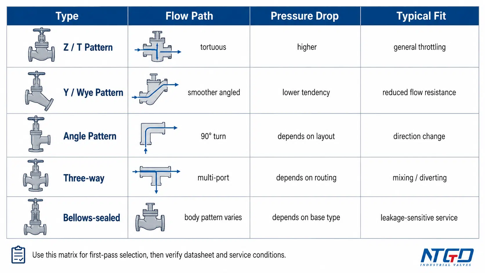
Globe Valve Type Comparison: Flow Path, Pressure Drop, and Applications
The table below compares the main body patterns and special globe valve types by their selection logic.
Body Pattern Comparison Matrix
Use this matrix to quickly compare the three main globe valve body patterns based on flow requirements, pressure drop constraints, and piping layout.
| Globe Valve Type | Main Selection Logic | Flow Path / Body Feature | Pressure Drop Tendency | Common Application Fit | Main Caution |
|---|---|---|---|---|---|
| Z-pattern / T-pattern globe valve | General throttling and regulation | Flow changes direction through the body and across the seat | Usually higher than smoother flow path designs | General process control, clean fluids, common throttling service | Verify allowable system pressure drop; high velocity or erosive service can increase seat and trim wear. |
| Y-pattern / Wye pattern globe valve | Throttling with reduced flow resistance | Angled internal path creates smoother flow | Usually lower than Z-pattern in suitable conditions | Services where globe valve control is needed but pressure drop must be reduced | Smoother flow does not mean zero resistance; do not use it as a substitute for a full-bore low-loss valve without checking flow data. |
| Angle-pattern globe valve | Flow control plus 90-degree direction change | Inlet and outlet are arranged at an angle | Depends on design, opening, and service conditions | Compact layouts, direction-change points, throttling service | Verify flow direction, orientation, drainage, media retention risk, and maintenance access. |
Special Type Comparison
This table helps determine when a special-purpose globe valve is needed instead of a standard body pattern.
| Special Type | Why It Is Selected | What It Mainly Solves | Common Fit | Main Caution |
|---|---|---|---|---|
| Three-way globe valve | Mixing, diverting, or routing flow | Multi-port flow configuration | Flow routing, mixing lines, diverting service, process changeover | Must confirm port function, pressure balance, actuator logic, and leakage expectation. |
| Bellows-sealed globe valve | Reducing external leakage through the stem area | Stem sealing and fugitive emission control | Toxic, volatile, hazardous, vacuum, or leakage-sensitive service | Must confirm bellows material, cycle expectations, pressure-temperature limits, backup packing, and maintenance method. |
This comparison shows why “globe valve type” is not a single-layer decision. Body pattern, flow function, sealing design, material, and service condition all influence the final specification.
Globe Valve Selection Framework
A practical globe valve selection guide should start with service conditions, not with a product list. The valve type should be selected only after the process requirements are clear. For broader valve family screening, the same industrial valve selection criteria should still be checked before narrowing the choice to a specific globe valve type.
Start with Flow Requirement and Throttling Need
First, define what the valve must do. To choose the right globe valve, start by defining whether the line needs throttling, shut-off, pressure-drop control, or automated operation.
Ask:
- Is the valve mainly for throttling?
- Does it need frequent adjustment?
- Is it used for on-off isolation only?
- Does the line need stable control under changing operating conditions?
- Is pressure drop acceptable?
- Is low flow resistance more important than control accuracy?
- Will the valve be manually operated or automated?
If the service requires stable throttling or regulation, a globe valve may be a suitable choice. If the line only needs low-resistance full-open isolation, another valve type may be more appropriate. If the system requires very fast opening or closing, the selected valve type and actuator should also be reviewed before final specification.
Check Pressure Drop and Flow Direction
Pressure drop is one of the most important factors in globe valve selection.
A Z-pattern globe valve usually creates higher pressure drop because the flow path changes direction through the body. A Y-pattern globe valve may reduce pressure loss by using a smoother angled path. An angle-pattern globe valve can fit applications where the line already needs a 90-degree turn.
Before final selection, compare:
- required flow rate;
- allowable pressure loss;
- valve size;
- body pattern;
- trim design;
- opening position;
- flow direction;
- manufacturer datasheet information.
Do not assume exact pressure drop or Cv values from the valve type alone. The final value depends on the manufacturer’s design, valve size, trim, opening, flow conditions, and calculation method.
Flow direction also matters. Incorrect flow direction may increase operating force, change seat loading, reduce seat sealing effectiveness, accelerate local trim wear, or affect leakage behavior. Always follow the permanent flow direction marking on the valve body, the manufacturer datasheet, and the installation instructions for the selected valve.
Match Media, Material, Seat, and Trim
Media compatibility affects body material, trim, seat, packing, gasket, and bellows selection.
| Media / Service Condition | Selection Impact |
|---|---|
| Clean water or general non-corrosive service | Standard materials may be suitable, but pressure and temperature still need confirmation. |
| Steam or high-temperature service | Body, bonnet, packing, gasket, seat, and trim must be checked for temperature suitability. |
| Corrosive media | Body and trim materials must resist chemical attack under actual concentration and temperature. |
| Abrasive or dirty media | Seat and trim wear risk increases; special trim or another valve type may be needed. |
| Toxic or volatile media | Bellows-sealed construction may be considered for external leakage control. |
| Viscous media | Flow resistance, cleaning, and maintenance requirements should be checked carefully. |
| Leakage-sensitive service | Stem sealing, packing, bellows design, and leakage expectations must be reviewed. |
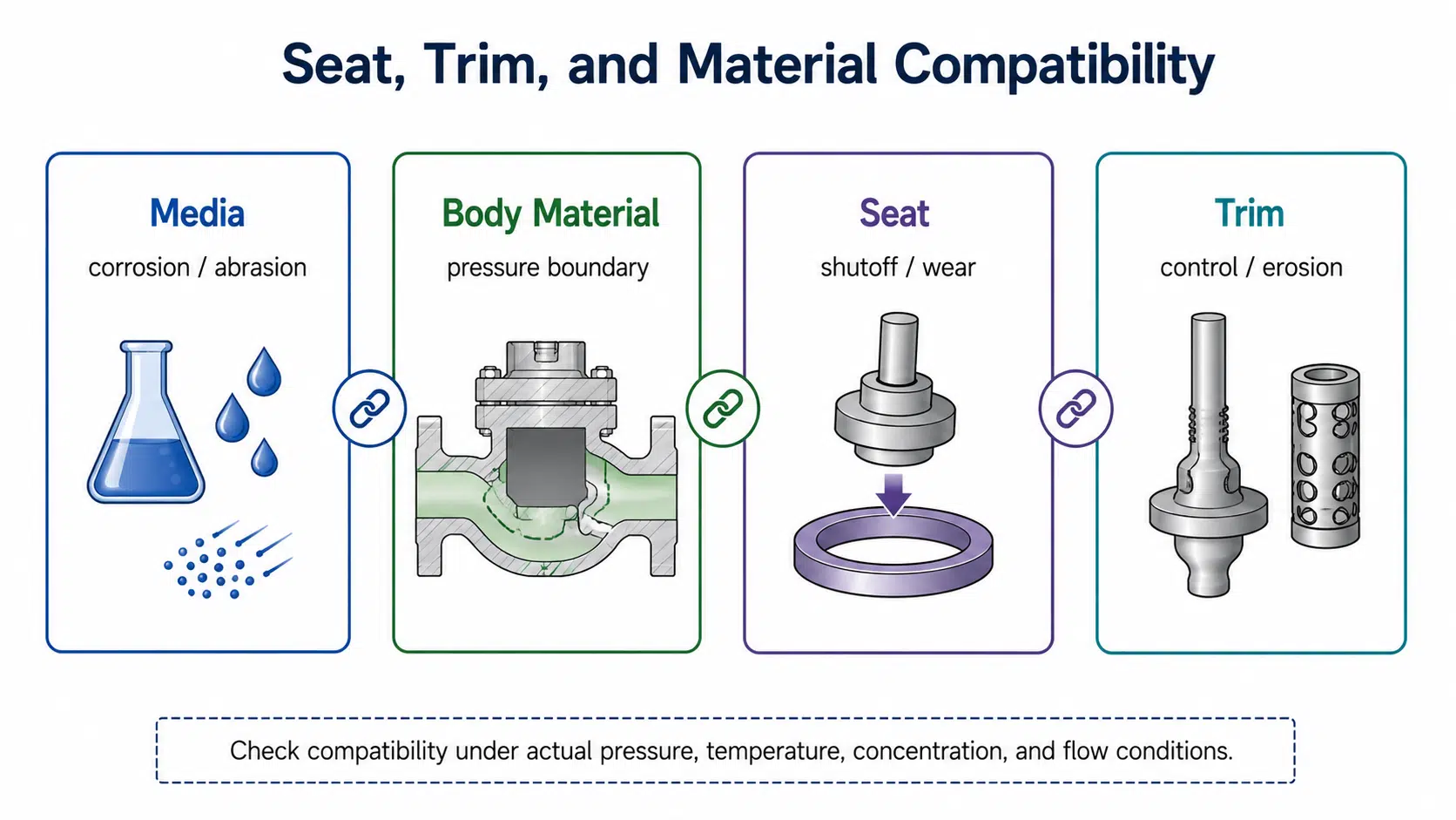
Material selection should never be guessed from the valve type name, and globe valve seat material should be reviewed together with media, temperature, pressure, leakage expectation, and trim design.
As a general valve-selection principle, the suitability of a valve depends on the materials used in relation to the conveyed fluid as well as the mechanical design.
It must be checked against the actual media, concentration, operating pressure, operating temperature, velocity, and maintenance expectations. For corrosive service, valve corrosion solutions should be reviewed together with body material, trim material, packing, gasket, and operating temperature. For corrosive or erosive service, the body material alone is not enough; seat, trim, packing, and gasket compatibility can decide whether the valve remains stable in operation or suffers early wear, leakage, or sticking. Body construction should also be reviewed, especially when comparing cast steel vs forged steel globe valves for pressure, size, and service severity.
Confirm Pressure, Temperature, Actuation, and Maintenance Access
A globe valve may be available in many pressure classes and materials, but the correct rating depends on the actual design, body material, applicable standard, end connection, and operating temperature.
Before specification, confirm:
- design pressure;
- operating pressure;
- design temperature;
- operating temperature;
- pressure class;
- body material;
- trim and seat material;
- end connection;
- actuation method;
- installation orientation;
- maintenance space.
When pressure class and differential pressure become the controlling factors, a high pressure globe valve should be checked against the project datasheet and service conditions.
Operation method also affects selection.
| Operation Type | Typical Use | Selection Check |
|---|---|---|
| Manual operation | Occasional local operation | Check handwheel access, operating torque, and maintenance space. |
| Pneumatic actuation | Frequent modulation or automated control | Check air supply, fail position, actuator sizing, and control signal. |
| Electric actuation | Remote operation where electric control is preferred | Check power supply, speed, torque, enclosure, and control requirements. |
| Control valve assembly | Continuous process control | Check actuator, positioner, trim, flow characteristic, and system response together. |
Maintenance access is often overlooked, especially when globe valve maintenance requires checking the packing, stem, seat, disc, body, or bonnet after installation. Where bolted pipeline access and maintenance clearance matter, flanged globe valves may provide a more practical installation route.
Use Standards as a Final Fit-Check
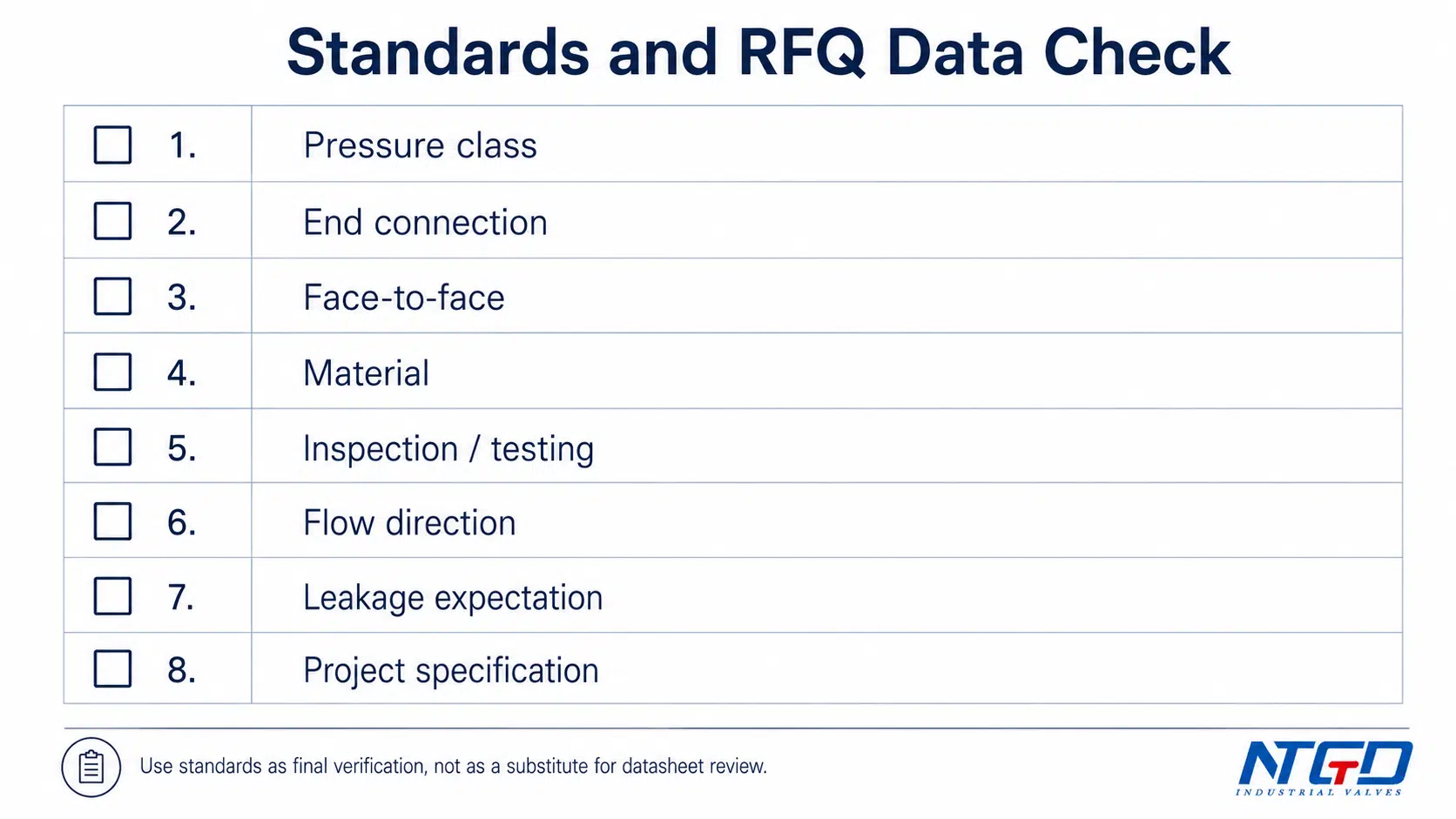
Globe valve design standard and globe valve standard questions should be handled as a final fit-check, not as the main topic of this page.
Depending on project requirements, relevant standards may relate to pressure-temperature rating, pressure boundary design, end connections, inspection and testing, face-to-face dimensions, fugitive emission requirements, material certification, and project-specific purchasing specifications; for example, ASME B16.34 covers pressure-temperature ratings, dimensions, tolerances, materials, testing, and marking for relevant valve constructions.
The exact standard requirement must come from project documents, applicable codes, and manufacturer datasheets. Inspection and testing requirements should also be confirmed, including pressure test methods for industrial valves when the project specification requires hydrostatic or leakage verification. This article should not be used as a substitute for a complete standard or compliance review.
Application Mapping and Fit / Avoid Checklist
The table below gives a practical starting point for matching service conditions to globe valve types. It is not a substitute for a datasheet or project specification, but it helps narrow the selection direction.
Application Condition → Recommended Globe Valve Type
| Application Condition | Likely Type Direction | Why It Fits | Extra Check |
|---|---|---|---|
| General throttling in clean process lines | Z-pattern / T-pattern globe valve | Common design for flow regulation | Confirm the total system pressure drop remains within the process requirement. |
| Need for lower pressure drop than a standard pattern | Y-pattern / Wye pattern globe valve | Smoother angled flow path | Verify whether the smoother flow path is enough to meet the required flow and pressure-loss target. |
| Pipeline needs a 90-degree direction change | Angle-pattern globe valve | Combines direction change with flow control | Confirm flow direction, drainage, orientation, and bonnet access before installation. |
| Mixing or diverting flow | Three-way globe valve | Designed for multi-port routing | Confirm port arrangement, pressure balance, actuator logic, and leakage expectation. |
| Toxic, volatile, or leakage-sensitive media | Bellows-sealed globe valve | Reduces stem leakage risk | Confirm bellows material, cycle expectation, pressure-temperature limit, and backup packing arrangement. |
| High-temperature or steam service | Properly rated steam globe valve with suitable material and packing | Globe valves are commonly used in regulating service | Confirm pressure-temperature rating, packing suitability, and trim material. |
| Corrosive media | Material-selected globe valve | Body, seat, and trim compatibility are critical | Confirm media concentration, operating temperature, trim material, and gasket compatibility. |
| Dirty or abrasive media | Use caution; special trim or another valve type may be needed | Seat and trim wear can become severe | Confirm solids content, velocity, seat / trim wear plan, and maintenance interval expectation. |
| Low pressure drop priority | Y-pattern may help, but another valve type may be more suitable | Globe valves usually create more resistance than straight-through valves | Compare total system pressure loss before accepting any globe valve type. |
For LNG or ultra-low-temperature service, a cryogenic globe valve should be checked separately because material, sealing, bonnet design, and testing requirements change significantly.
When a Globe Valve Is a Good Fit
A globe valve is usually a good candidate when the system needs controlled flow rather than only open / closed isolation.
Good fit conditions include:
- throttling or regulating service;
- frequent flow adjustment;
- need for stable control across changing operating conditions;
- clean or moderately clean media;
- acceptable pressure drop;
- applications where shut-off and control performance both matter;
- services where top-entry maintenance access is useful;
- systems where trim, seat, and actuator can be properly specified.
A globe valve is especially useful when the process needs a controlled relationship between stem movement and flow change. Final performance still depends on trim design, actuator selection, flow conditions, and installation quality.
When to Reconsider the Selection
A globe valve is not the best fit for every pipeline.
Reconsider the selection when:
- the system requires very low pressure drop;
- full-bore flow with minimum restriction is the main priority;
- the media contains heavy solids or abrasive particles;
- seat and trim erosion risk is high;
- the service only needs simple on-off isolation;
- the valve will be installed where maintenance access is poor;
- pressure / temperature rating is unclear;
- material compatibility has not been verified;
- the required flow direction cannot be installed correctly;
- the system requires very fast opening or closing and the valve / actuator combination has not been reviewed.
If the line mainly needs low-resistance isolation rather than throttling, compare gate valves vs globe valves before finalizing the valve type. For heavy solids or slurry service, valves for slurry applications should be reviewed before assuming a globe valve can handle the wear risk.
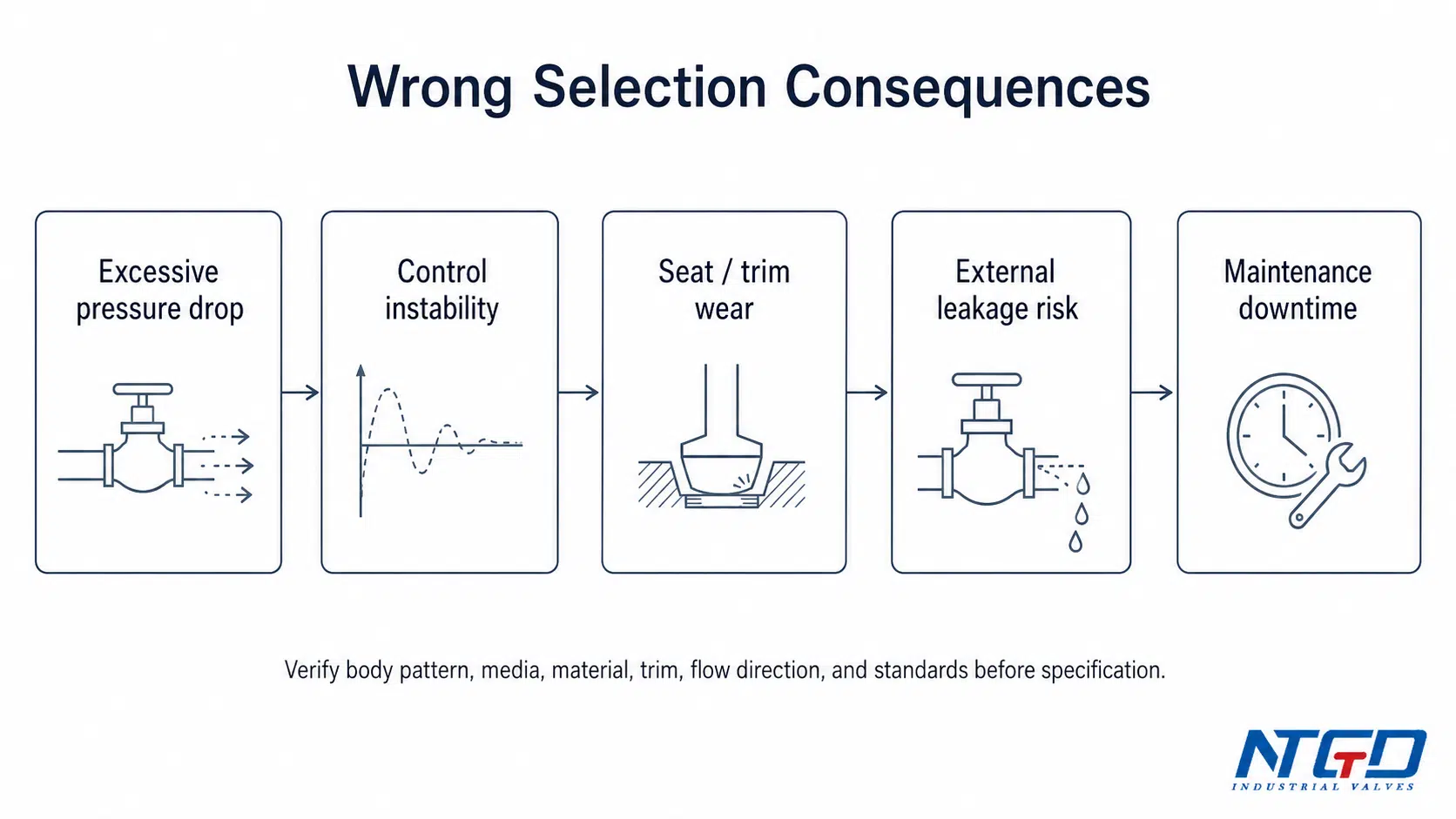
In these cases, the project may need another valve type or a specially designed globe valve with suitable trim, material, and maintenance planning. A wrong choice can lead to control instability, premature trim wear, increased maintenance cost, or unplanned downtime.
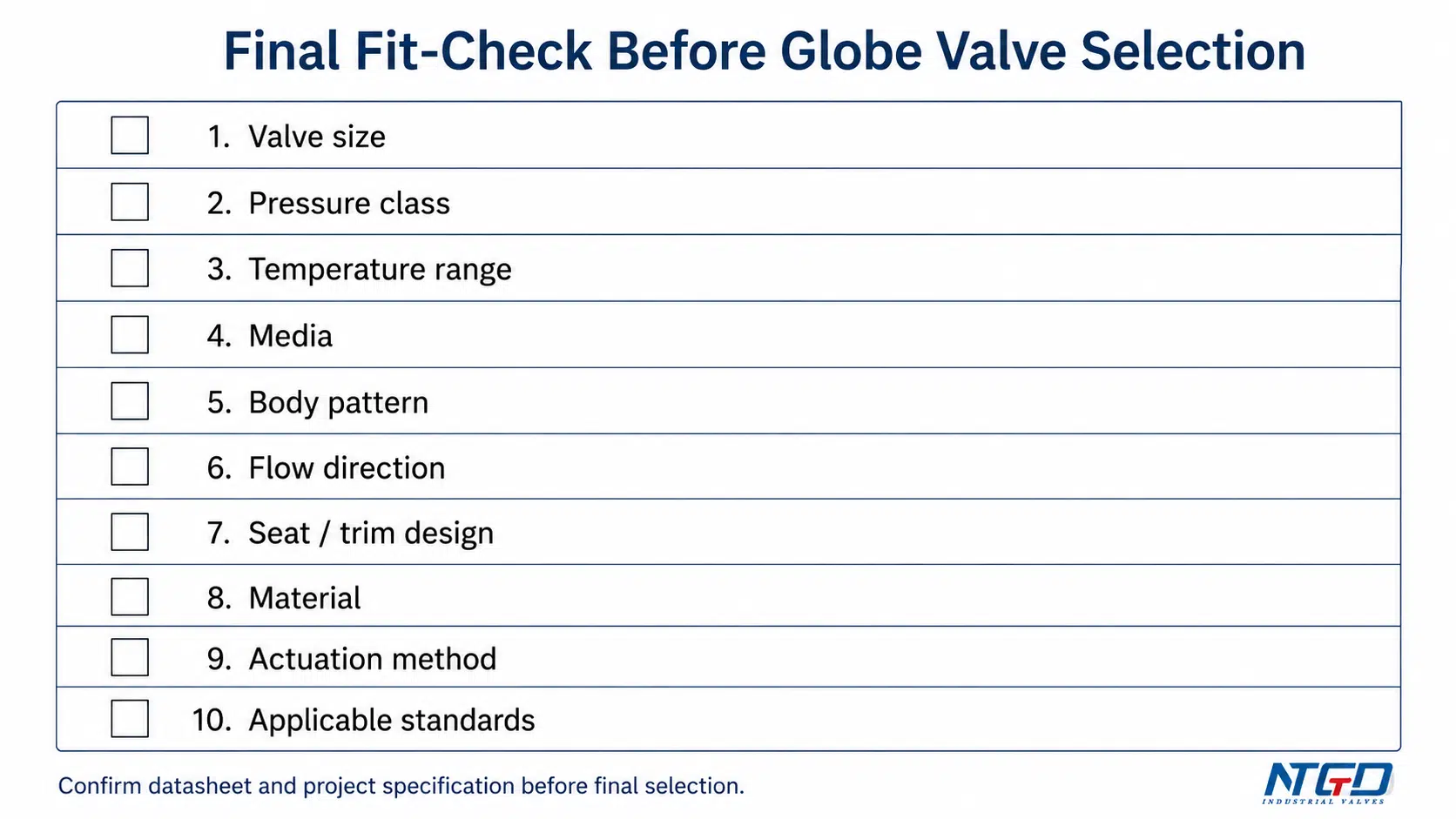
Final RFQ Fit-Check
Before sending an RFQ or confirming the specification, check the following items. If the piping specification requires flanged ends, the flange globe valve option should be checked together with pressure class, face-to-face dimension, and gasket requirements.
| Fit-Check Item | Why It Matters |
|---|---|
| Valve size | Affects flow capacity, pressure drop, and installation fit |
| Pressure class | Must match line pressure and applicable specification |
| Temperature range | Affects body material, packing, gasket, seat, and trim selection |
| Media | Drives material, corrosion, erosion, and leakage-control decisions |
| Body pattern | Determines flow path and pressure drop tendency |
| Flow direction | Must follow manufacturer instructions |
| Seat / trim design | Affects throttling, shut-off, wear, and control stability |
| Body and trim material | Must match media, temperature, and corrosion conditions |
| End connection | Must match the piping standard and installation requirement |
| Actuation method | Must match operation frequency and control needs |
| Maintenance access | Must allow safe inspection, packing adjustment, and servicing |
| Applicable standards | Must be verified from project specification and datasheet |
This final check is especially important for steam, chemical, high-temperature, corrosive, hazardous, automated, or leakage-sensitive services.
FAQ About Globe Valve Types and Selection
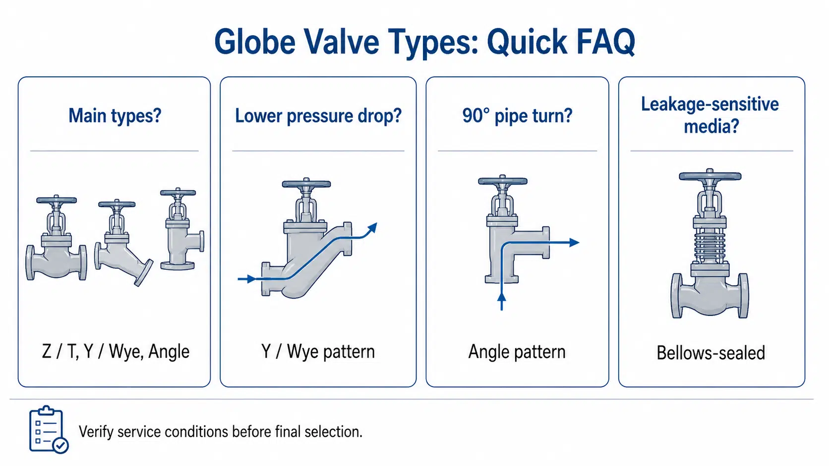
What are the main types of globe valves?
The main globe valve body types are Z-pattern / T-pattern, Y-pattern / Wye pattern, and angle-pattern globe valves. Three-way globe valves and bellows-sealed globe valves are also common, but they are better understood as special configuration or special-service types rather than the same body-pattern category.
Is a Z-pattern globe valve the same as a T-pattern globe valve?
In many industrial references, Z-pattern, T-pattern, Tee-pattern, and standard pattern globe valves refer to the common globe valve body design where the fluid changes direction through the body and across the seat. Naming may vary by manufacturer or region, so the datasheet should be checked.
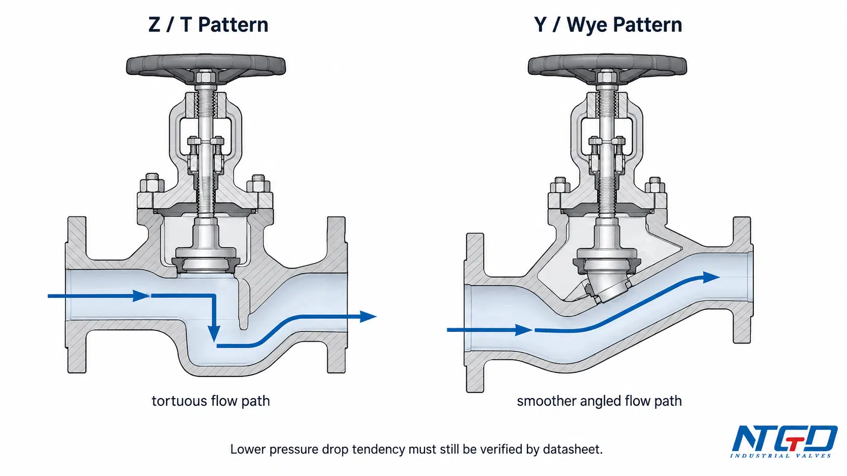
What is the main difference between Z-pattern and Y-pattern globe valves?
The main difference is the internal flow path. For a deeper service-fit comparison, see this guide to tee pattern globe valve vs y pattern globe valve. A Z-pattern globe valve uses a more tortuous flow path that supports stable throttling but usually creates higher pressure drop. A Y-pattern globe valve uses a smoother angled path, so it is often considered when the system still needs globe valve control but must reduce flow resistance.
Which globe valve type has lower pressure drop?
A Y-pattern globe valve usually provides a smoother flow path than a standard Z-pattern globe valve and may reduce pressure drop in suitable applications. Actual pressure drop still depends on valve size, trim design, opening position, flow rate, manufacturer data, and system calculation.
When should an angle-pattern globe valve be selected?
An angle-pattern globe valve is useful when the piping layout requires a 90-degree flow turn and the system still needs throttling or controlled shut-off. It may reduce the need for an extra elbow, but flow direction, orientation, drainage, and maintenance access must be confirmed.
Do all leakage-sensitive services require a bellows-sealed globe valve?
Not always. A bellows-sealed globe valve is often considered when external stem leakage risk is critical, especially for toxic, volatile, hazardous, expensive, vacuum, or environmentally sensitive media. For less severe services, packing design, maintenance requirements, and project leakage expectations should also be reviewed before deciding whether bellows sealing is necessary.
Does globe valve flow direction matter?
Yes. Flow direction can affect pressure drop, seat loading, leakage behavior, operating force, and trim wear. Always follow the manufacturer’s flow direction marking and datasheet instructions.
How do I select the right globe valve type?
Start with the service function: throttling, shut-off, mixing, diverting, or leakage control. Then choose the appropriate body pattern, check pressure drop and flow direction, match media with material / trim / seat design, confirm pressure-temperature rating, decide the operation method, and verify applicable project standards.
What should be checked for globe valve design standards?
Start by checking the project specification, pressure class, material, end connection, inspection / testing requirement, face-to-face requirement, leakage expectation, and any fugitive emission or certification requirement. The exact standard or code depends on the project and must be verified against the manufacturer datasheet and purchasing specification.
Conclusion
Globe valve selection should start with the service requirement, not only with valve size or pressure class. The main globe valve body patterns—Z-pattern, Y-pattern, and angle-pattern—differ mainly in flow path, pressure drop, and piping layout. Three-way and bellows-sealed globe valves add special flow-routing and leakage-control functions.
For most industrial projects, the best approach is to compare the body pattern, confirm the throttling requirement, check pressure drop, match materials and trim to the media, and verify the final specification against the datasheet and project standard.
A well-selected globe valve can provide stable throttling and reliable service. A poorly selected one may create excessive pressure loss, leakage risk, trim wear, maintenance difficulty, control instability, or incorrect operation in the pipeline.
Need Help Selecting a Globe Valve Type?
If you are selecting a globe valve for steam, chemical, water treatment, fuel oil, high-temperature, corrosive, automated, or leakage-sensitive service, NTGD Valve can help review the application conditions before final specification. Share the media, valve size, pressure class, temperature, flow-control requirement, end connection, preferred material, and operation method so the valve type, trim, and sealing design can be checked more accurately.
With those service details, the selected body pattern, trim design, material choice, and sealing arrangement can be cross-checked for mismatch before the valve specification is finalized.
