Author Name: Bruce Zheng
Author Role: Co-Founder and Valve Engineer at NTGD Valve
Author Bio: Bruce Zheng is Co-Founder and Valve Engineer at NTGD Valve, focusing on industrial valve selection, application, and technical content for global B2B buyers.
Last Updated: May 21, 2026
Quick Answer: How Does a Globe Valve Work?
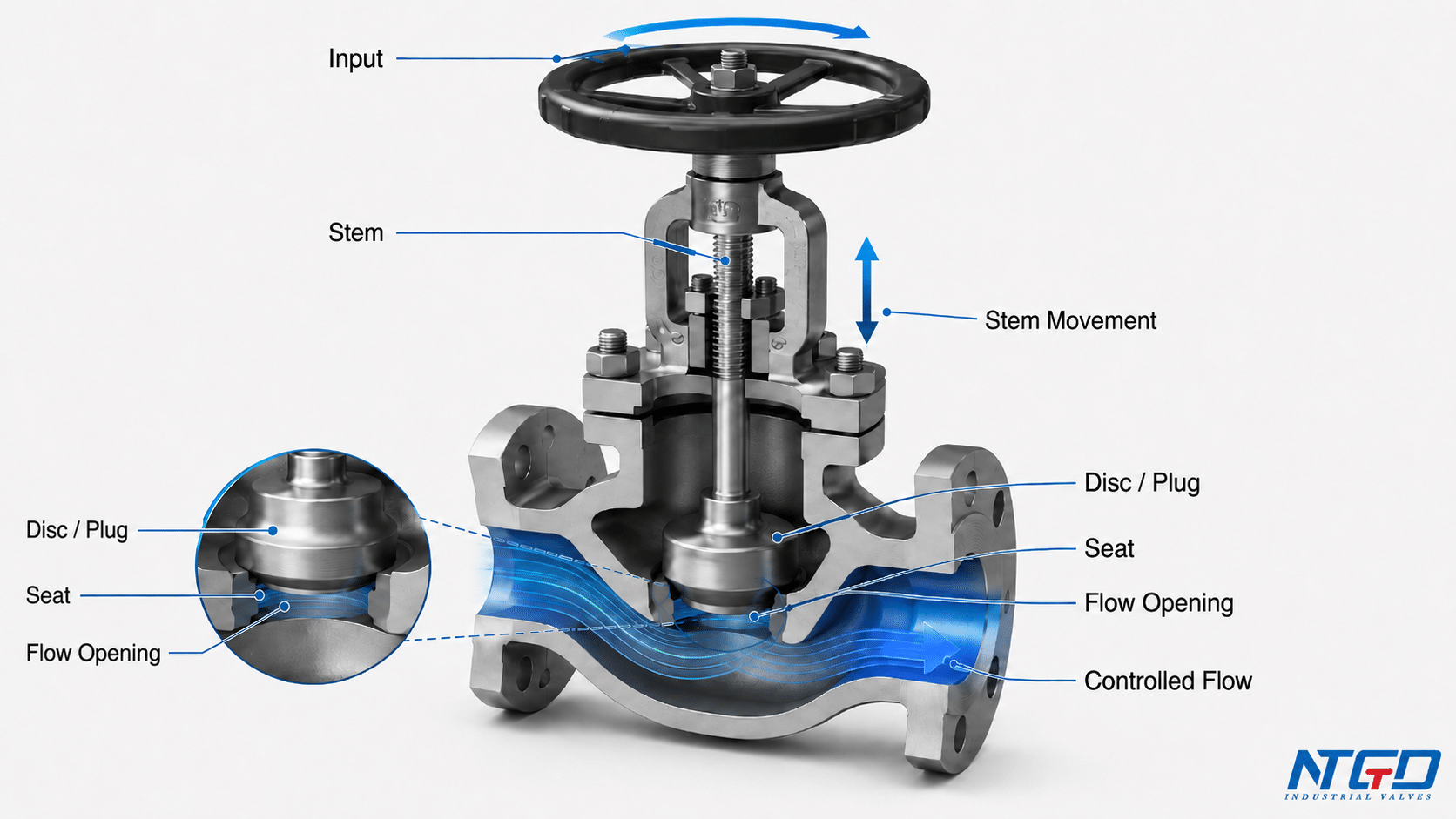
Unlike rotary valve designs, a globe valve works through linear motion: the stem moves a disc or plug up and down against a fixed seat inside the valve body. As the handwheel or actuator moves the stem, the stem positions the disc or plug closer to or farther away from the seat. This changes the opening between the disc and the seat, which controls the available flow area.
When the disc is lifted away from the seat, fluid can pass through the valve. When the disc is held partly open, the valve can regulate or throttle the flow. When the disc is pressed firmly against the seat, the valve shuts off the flow.
This is the basic globe valve working principle:
- Handwheel or actuator input
- Stem movement
- Disc / plug movement
- Seat opening changes
- Flow area changes
- Flow is throttled or shut off
This linear motion gives a direct mechanical relationship between stem travel, disc position and flow area. That is why globe valves are commonly used for controlled throttling rather than only simple on-off isolation.
What Is a Globe Valve? Scope of This Working Principle Guide
Short Definition of a Globe Valve
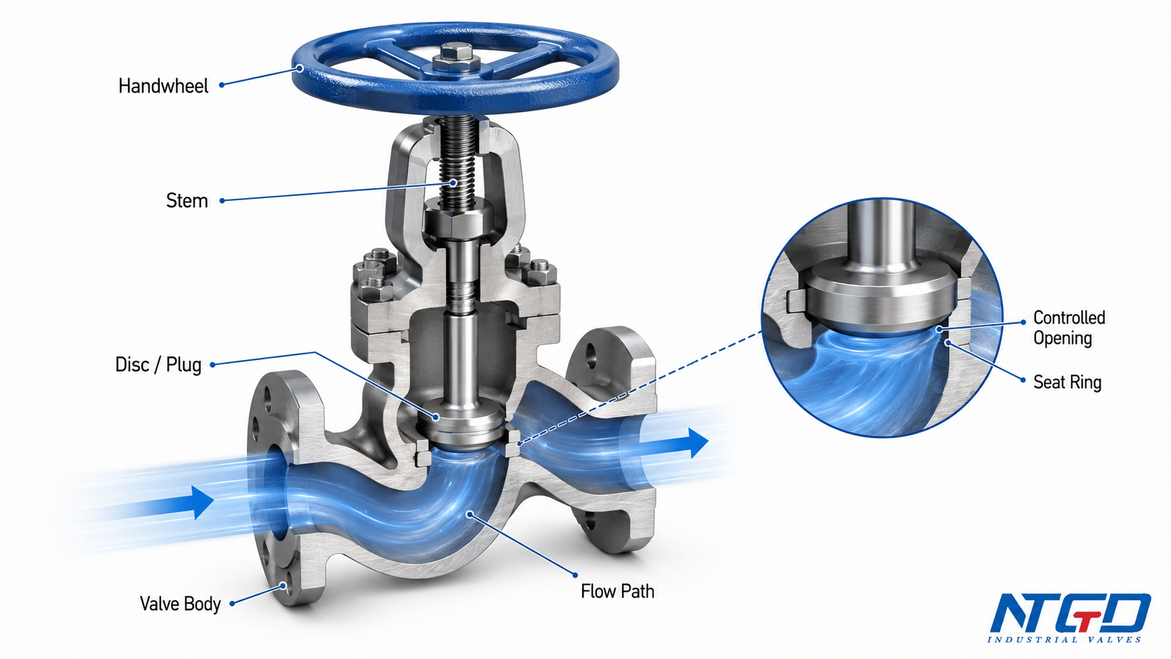
A globe valve is a linear-motion valve used to start, stop, and regulate fluid flow. Inside the valve body, a movable disc or plug works against a stationary seat. The stem moves the disc or plug in a straight-line motion, usually by manual handwheel operation or by an actuator.
Because the disc can be positioned at different heights above the seat, a globe valve is commonly used where flow control or throttling is more important than having the lowest possible flow resistance.
What This Guide Covers—and What It Does Not Cover
This guide focuses on the general working principle of a globe valve. It explains how the stem, disc or plug, seat, body flow path, and shutoff surface work together.
It does not try to become a full guide to every globe valve topic. In particular, this article does not cover full globe valve types, full parts lists, selection rules, maintenance procedures, installation instructions, pressure drop calculation, or flow direction design in depth.
Those topics answer different engineering questions. For example, full parts identification, valve selection, maintenance, flow direction, and product-specific configurations should be handled by separate technical resources rather than being expanded inside this working principle guide.
For a full component-level breakdown, keep this article focused on working motion and use NTGD’s globe valve parts and components guide when the main question is body, bonnet, packing, gasket, trim or part identification.
Key Working Components Inside a Globe Valve
A globe valve has many parts, but not every part needs to be explained in detail to understand how the valve works. For the working principle, the most important components are the input device, stem, disc or plug, seat, and body flow path.
| Working component | Basic function in the globe valve mechanism | Why it matters |
|---|---|---|
| Handwheel or actuator | Provides the input force or motion | Converts manual or actuated input into stem travel, making it the starting point of control movement |
| Stem | Transfers motion from the handwheel or actuator to the disc or plug | Transfers linear motion to the disc or plug, so stem position directly affects disc position |
| Disc or plug | Moves in relation to the seat | Converts stem movement into a change in flow restriction at the seat opening |
| Seat / seat ring | Provides the fixed sealing surface | Creates the fixed sealing reference point for shutoff and flow control |
| Valve body | Contains the internal flow path | Redirects fluid through the seat area, supporting control behavior while adding resistance |
Handwheel or Actuator: The Input Device
The input device is the starting point of globe valve operation. In a manual globe valve, the handwheel moves the stem. In an actuated globe valve, an actuator provides the movement instead.
For this article, the important point is simple: the handwheel or actuator does not directly control the fluid by itself. It moves the stem, and the stem controls the internal closure element.
Stem: The Motion Transfer Part
The stem is the link between the external operating device and the internal disc or plug. Its function is to transfer movement into the valve body and control the vertical position of the closure element.
In a globe valve, this movement is linear. That linear stem travel is what creates a controlled relationship between the operating input and the position of the disc or plug at the seat.
Disc or Plug: The Moving Closure Element
The disc or plug is the moving part that changes the flow restriction. As the stem moves, the disc or plug changes its position relative to the seat opening.
A higher disc position generally creates more available flow area. A lower position reduces the opening. When the disc or plug is fully seated, the valve moves into shutoff.
Seat / Seat Ring: The Fixed Sealing Surface
The seat is the stationary surface inside the valve. It gives the moving disc or plug a fixed reference point for both throttling and shutoff.
This fixed seat is important because flow control depends on the distance between the moving closure element and the seat opening. Shutoff depends on proper contact between the disc or plug and the seat sealing surface.
Body and Flow Path: Where the Fluid Changes Direction
The body holds the internal flow path. In many globe valve designs, the flow path is not straight through the valve. The fluid changes direction as it passes through the seat area.
This internal path is one reason globe valves are useful for regulation, but it is also why they usually have higher pressure drop than many straight-through valve designs.
The Core Globe Valve Mechanism: From Input to Flow Area
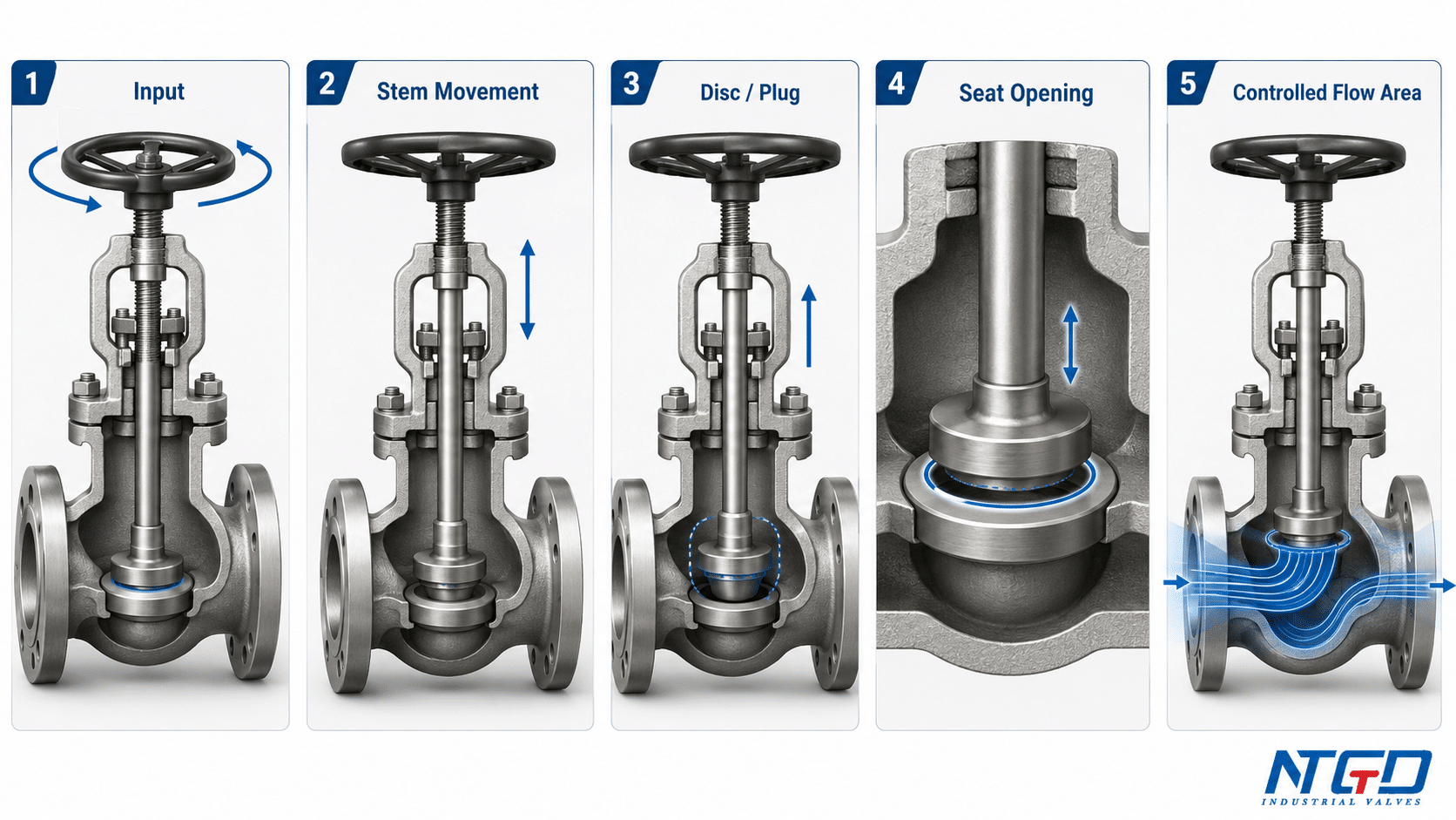
The globe valve mechanism is best understood as a motion chain. Each part passes the action to the next part until the flow area changes.
Step 1: Input Moves the Stem
The operator or actuator provides the first movement. In a manual valve, this usually starts with handwheel movement. In an automated valve, the actuator provides the motion.
The exact external operating method may vary, but the internal goal is the same: move the stem in a controlled way.
Step 2: The Stem Moves the Disc or Plug
The stem is connected to the disc or plug. As the stem moves, it raises or lowers the closure element.
This is why globe valves are described as linear-motion valves. The closure element does not swing, slide like a gate, or rotate through a quarter turn. This linear displacement creates a direct mechanical relationship between handwheel or actuator position and the flow opening inside the valve.
Step 3: The Disc or Plug Changes the Seat Opening
As the disc or plug moves away from the seat, the opening becomes larger. As it moves closer to the seat, the opening becomes smaller.
This opening is the controlling point of the valve. A change in disc or plug position changes the available passage for fluid at the seat area.
Step 4: Seat Opening Changes the Flow Area
The flow area is the available space for fluid to pass between the disc or plug and the seat. When this area is large, more flow can pass. When it is small, flow is restricted.
This change in flow area is the core mechanism behind globe valve throttling. The valve can restrict or increase flow by positioning the disc or plug at controlled intermediate points instead of only moving between fully open and fully closed.
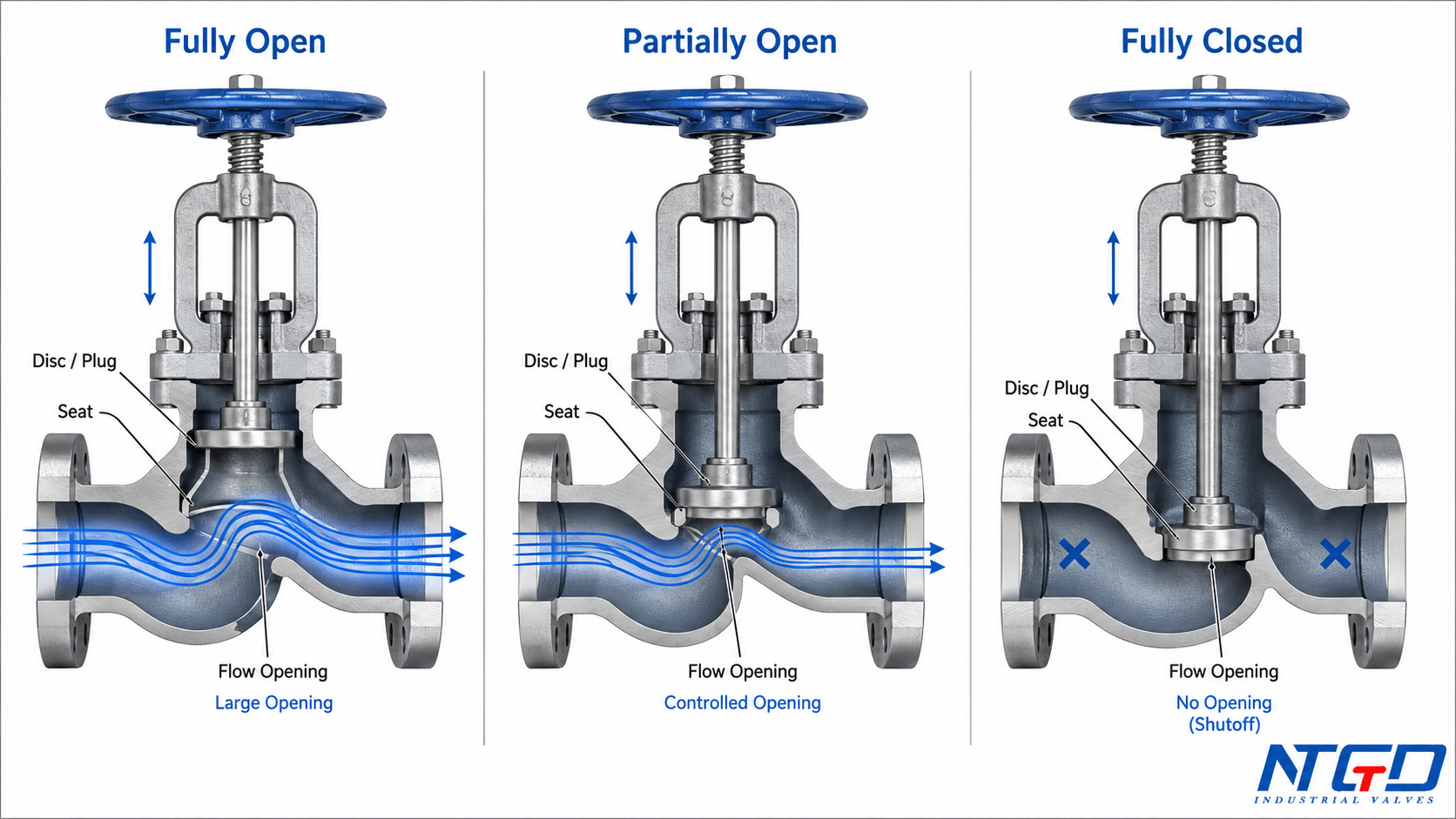
Open, Partially Open and Closed Positions
A globe valve is easiest to understand by looking at three operating positions: fully open, partially open, and fully closed.
| Valve position | Disc / plug position | Flow behavior | Main purpose |
|---|---|---|---|
| Fully open | Lifted away from the seat | Maximum available opening for that valve design | Allow flow |
| Partially open | Held between open and closed | Restricted flow area | Throttling / regulation |
| Fully closed | Pressed against the seat | Flow path shut off at the seat | Shutoff |
Fully Open Position
In the fully open position, the disc or plug is lifted away from the seat. This creates a larger opening through the seat area and allows fluid to pass through the valve.
However, “fully open” does not mean the valve has the same flow resistance as a straight-through valve. The internal body path can still create pressure loss, so fully open should not be understood as no resistance.
Partially Open Position for Throttling
In the partially open position, the disc or plug is not fully lifted and not fully seated. It stays somewhere between the open and closed positions.
This is where globe valves are commonly used for throttling. By changing the disc or plug height, the valve changes the flow area. A smaller opening restricts flow. A larger opening allows more flow.
The relationship between disc position and flow rate is not always perfectly linear. However, the defined stem travel and fixed seat geometry allow more repeatable throttling than simple on-off valve movement.
Fully Closed Position for Shutoff
In the fully closed position, the disc or plug is pressed against the seat. The sealing surfaces come into contact, and the flow path is closed at the seat.
The shutoff action depends on the condition of the disc, seat, stem movement, and overall valve design. If the sealing surfaces are damaged, contaminated, or unsuitable for the service, the valve may not perform as expected. Detailed leakage diagnosis belongs in a maintenance or troubleshooting guide, not in this working principle article.
How the Disc and Seat Create Shutoff
Disc-seat Contact and Sealing Surface
The shutoff principle of a globe valve comes from the contact between the disc or plug and the seat. The seat is fixed in the valve body. The disc or plug moves into contact with it.
When the disc or plug contacts the seat properly, the flow path through the seat area is closed. This is different from throttling, where the disc or plug remains partly away from the seat to leave a controlled opening.
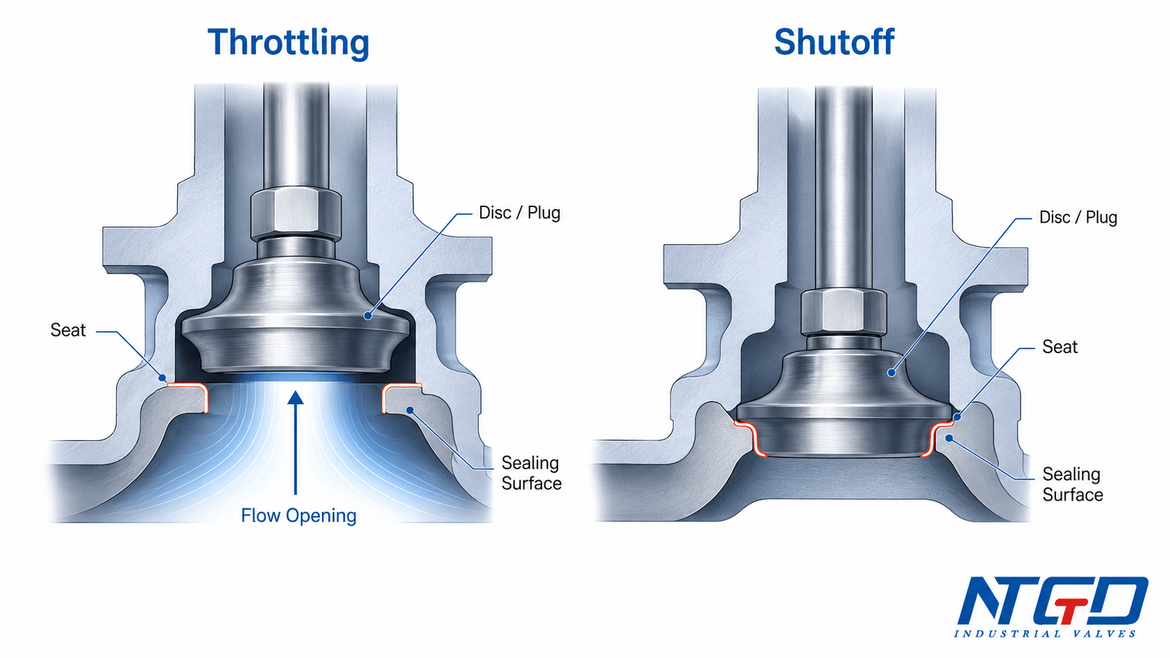
Why Shutoff Is Different from Throttling
Throttling and shutoff use the same main parts, but they are not the same operating condition.
In throttling, the valve is intentionally held in an intermediate position. Fluid passes through a restricted opening, and the valve controls the flow by changing that opening.
In shutoff, the valve is moved to the closed position. The disc or plug is pressed against the seat to stop the flow through the valve.
During throttling, the disc-seat area remains exposed to flow velocity, turbulence and differential pressure. For continuous or severe regulating service, trim design, media condition, pressure drop and operating frequency should be checked carefully.
What This Does Not Cover About Leakage Diagnosis
This general explanation does not cover specific leakage diagnosis or repair procedures. If a globe valve does not shut off properly, possible causes may include seat wear, disc damage, foreign particles, stem alignment issues, packing issues, or incorrect service conditions.
Those problems require inspection and maintenance procedures. They should not be expanded inside this general working principle guide.
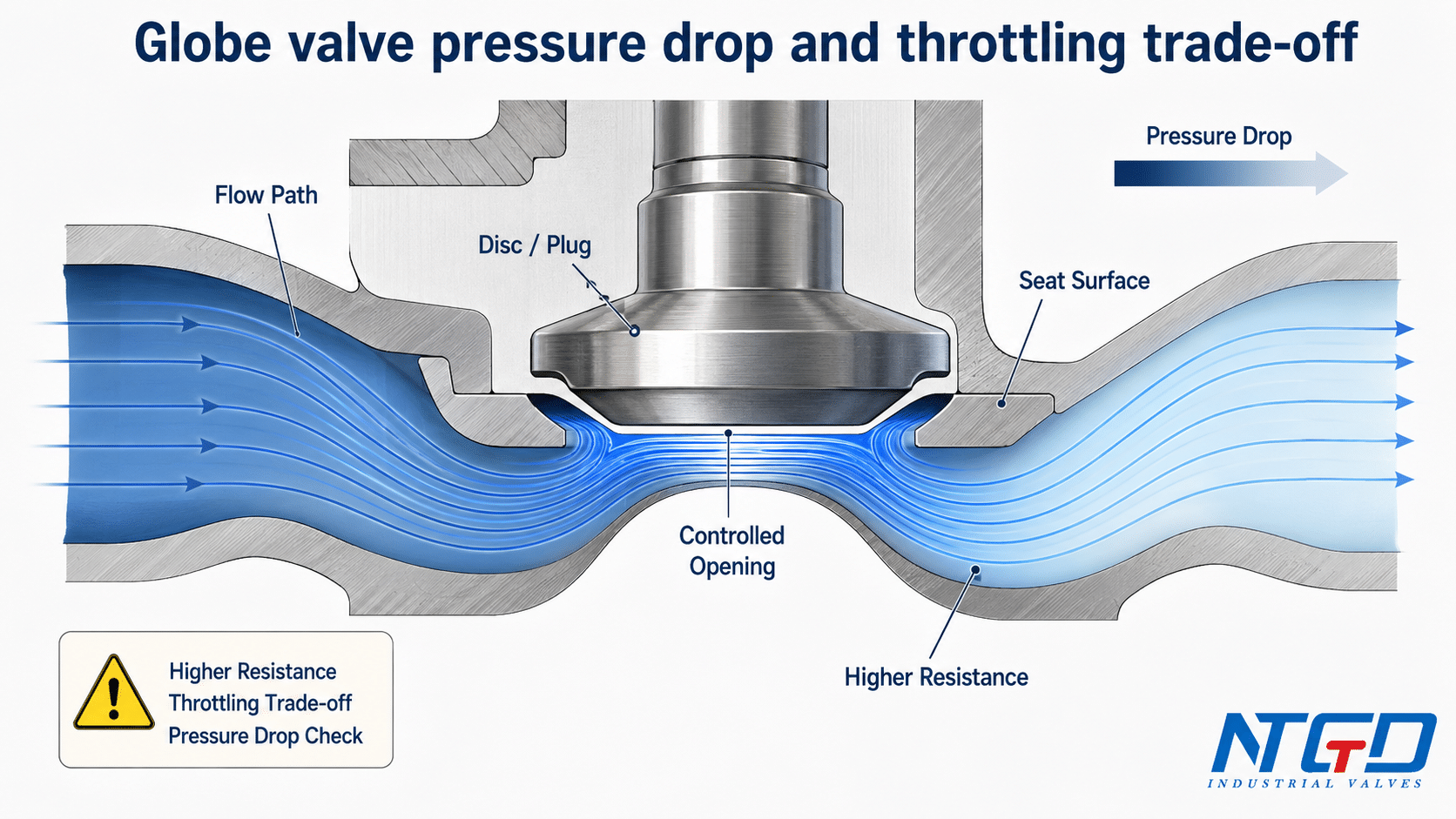
Flow Path, Pressure Drop and Throttling Behavior
Why the Flow Path Changes Direction
In many globe valve body designs, the fluid does not move through a simple straight passage. It enters the valve body, passes through the seat area, and changes direction before leaving the valve.
This flow path is part of what gives the globe valve its control behavior. The disc or plug is positioned directly against the seat opening, so the valve can regulate the available flow area with clear mechanical control.
Why Globe Valves Usually Have Higher Pressure Drop
Because the fluid changes direction inside the valve, globe valves usually create more pressure drop than many straight-through valve designs.
This higher pressure drop is a typical engineering trade-off in globe valve design. The redirected flow path and disc-seat control area support more precise regulation, while the system accepts more resistance than it would with many straight-through valve designs.
For body-pattern comparison, pressure-drop boundaries and broader type selection, use NTGD’s globe valve types and selection guide instead of expanding Z-pattern, Y-pattern or angle-pattern selection inside this working-principle page.
For external engineering background, this engineering handbook discussion of globe valves describes the disk-seat throttling mechanism, high head loss from multiple right-angle turns, and service-dependent flow direction considerations.
In real projects, this trade-off must be checked against system pressure drop allowance, pumping capacity, energy cost and process control requirements. The acceptable pressure drop depends on the service conditions, valve size, body pattern, trim design, flow rate, media, and system requirements.
Why This Design Helps Flow Regulation
The same geometry that creates resistance also helps the valve regulate flow. The disc or plug sits over the seat area, so changing its position changes the flow area in a controlled way.
This makes globe valves useful where the system requires frequent adjustment, throttling, or controlled flow reduction. The valve should still be selected carefully if the service has high differential pressure, high velocity, severe flashing or cavitation risk, abrasive media, or strict leakage requirements.
Flow Direction Caution: Confirm the Body Arrow and Datasheet
Many globe valves have a preferred flow direction. Flow direction can affect opening force, closing force, sealing behavior, wear, and control stability.
Correct flow direction confirmation is an important pre-installation step, but the final recommendation should come from the valve body arrow, datasheet, drawing, or manufacturer instruction—not from a general rule applied to all globe valves.
This article only explains the working principle. It does not replace a full globe valve flow direction guide or an installation manual.
What This Working Principle Means in Real Service
Where the Mechanism Supports Controlled Flow
A globe valve is often considered when the process needs controlled flow rather than simple on-off isolation. Its disc-seat mechanism allows intermediate positions, and those positions can be used to regulate flow through the valve.
This makes the globe valve useful in many industrial fluid control systems where throttling, flow adjustment, or stable shutoff behavior is required.
Where the Mechanism Has Practical Limits
The same linear-motion design also has inherent limits. It is not ideal for every service, especially where the main requirement is minimal pressure drop, very fast operation, or handling heavy solid particles.
These limits do not make the globe valve unsuitable. They mean the working principle must be matched to real service conditions. Media, pressure, temperature, flow rate, pressure drop allowance, shutoff requirement, installation direction, end connection, and actuation method all affect the final decision.

Service Data to Confirm Before RFQ
Before selecting or requesting a globe valve, the buyer or engineer should confirm the basic service conditions.
| RFQ item | Why it matters |
|---|---|
| Media | Affects material, trim, seat, and sealing suitability |
| Pressure and temperature | Affects body rating, material, and sealing design |
| Flow control requirement | Determines whether throttling performance is important |
| Pressure drop allowance | Helps check whether the globe valve flow path is acceptable |
| End connection | Affects installation and piping compatibility |
| Body pattern | May affect flow path and pressure drop |
| Material and seat design | Affects durability and service compatibility |
| Manual or actuated operation | Affects control method and automation needs |
| Preferred flow direction | Should be confirmed by body arrow, drawing, or datasheet |
Clear service data helps the engineering team judge whether a general globe valve design is suitable, or whether the service requires a high-pressure design, flanged connection, steam-service arrangement, bellow-seal configuration, angle-pattern body, or automated actuation.
FAQ
How is a manual globe valve opened, closed or throttled?
In a manual globe valve, turning the handwheel moves the stem. The stem changes the position of the disc or plug relative to the seat. When the disc or plug lifts away from the seat, the valve opens. When it moves closer to the seat, the valve restricts flow. When it seats fully, the valve closes.
How can you tell in the field whether a globe valve is open or closed?
It depends on the valve design. Some manual globe valves use stem travel, handwheel position, or position indication to show open or closed status. Actuated valves may provide local or remote position indication. The correct method should be confirmed from the valve design, drawing, tag information, or manufacturer instruction.
Does flow direction matter on a globe valve?
Yes, flow direction often matters. Many globe valves have a preferred flow direction because fluid force can affect opening force, closing force, sealing, wear, and control stability. Always check the body arrow, datasheet, drawing, or manufacturer instruction.
Can a globe valve be used for flow in both directions?
Not always. Some designs may tolerate flow in more than one direction, but many globe valves are installed with a preferred direction. The correct answer depends on the valve design, service condition, trim, and manufacturer instructions.
What happens if a globe valve is installed backwards?
Incorrect flow direction may affect shutoff performance, operating force, seat wear, packing load, control stability, or pressure drop. The exact effect depends on the valve design and service. This is why the body arrow and datasheet should be checked before installation.
Does a globe valve have high pressure drop?
A globe valve usually has higher pressure drop than many straight-through valve designs because the fluid changes direction inside the body and passes through the seat area. The actual pressure drop depends on valve size, body pattern, trim design, flow rate, media, and system conditions.
Why are globe valves used for throttling?
Globe valves are used for throttling because the disc or plug can be positioned between fully open and fully closed. This allows the valve to change the flow area gradually instead of only switching flow on or off.
What problems are related to the globe valve working principle?
Problems related to the globe valve working principle often involve the parts that control motion and sealing. Worn disc or seat surfaces may affect shutoff, stem or packing issues may increase operating force, and erosion around the disc-seat area may reduce throttling stability. Detailed inspection and repair decisions should be handled in a dedicated globe valve maintenance and troubleshooting guide.
For inspection steps, leakage classification and repair-or-replace decisions, route those issues to NTGD’s globe valve maintenance and troubleshooting guide rather than expanding maintenance procedures inside this working-principle page.
Is a globe valve quick to open and close?
A globe valve is generally not as fast as a quarter-turn valve because it uses linear stem movement. The disc or plug must travel through the required stem movement before the valve changes from open to closed or from closed to open. Globe valves are usually valued more for control and throttling than for rapid operation.
Conclusion
In summary, the globe valve’s linear-motion design—where the stem positions a disc or plug against a fixed seat—defines both its control strength and its practical limits. The same mechanism that supports throttling and shutoff also creates flow resistance that must be checked against real service conditions.
The globe valve working principle is not only about opening and closing. It is about how stem travel, disc or plug position, seat opening, flow area, pressure drop, and shutoff surface interact inside the valve body.
For real applications, this working principle should be connected to the actual service conditions. Pressure, temperature, media, pressure drop allowance, shutoff requirement, flow direction, body pattern, material, seat design, and actuation method all affect whether a globe valve is the right fit.
Application / Specification Support
If you are preparing a globe valve RFQ, confirm the service data before final selection. At minimum, review the media, pressure, temperature, flow rate, required control function, allowable pressure drop, end connection, material, seat design, operation method, and preferred flow direction.
A clear specification helps the valve supplier or engineering team review whether the application can use a general globe valve design, or whether the service requires a high-pressure design, flanged connection, steam-service arrangement, bellow-seal configuration, angle-pattern body, or automated actuation.
The following NTGD video provides a real product example of an actuated globe valve configuration. Use it as product context after reviewing the working principle and service data requirements above.
If the service moves into high-pressure conditions, review NTGD’s high pressure globe valve page for product-level configuration and specification support.
If the end connection is the main specification concern, NTGD’s flange globe valve page is the better product-level route than expanding flange construction inside this article.
