Globe valve parts include the body, bonnet, disc or plug, seat, stem, packing, gasket, trim, and handwheel or actuator. These globe valve components work together to stop, start, or regulate flow by moving the disc or plug toward and away from the seat.
For engineers and buyers, understanding globe valve parts is not only a naming exercise. Each part affects sealing performance, pressure boundary integrity, maintenance access, operating torque, leakage control, and RFQ accuracy. A correct parts list helps prevent specification gaps such as unclear trim material, missing packing requirements, wrong actuation assumptions, or incomplete seat and disc details.
This article explains the main parts of a globe valve, their functions, how they fit together in a diagram, and what to confirm before quotation.
This guide focuses on general globe valve parts and component functions. For service-specific valve selection, use the related product and structure pages linked below.
What Are the Main Parts of a Globe Valve?
Quick answer: main globe valve parts
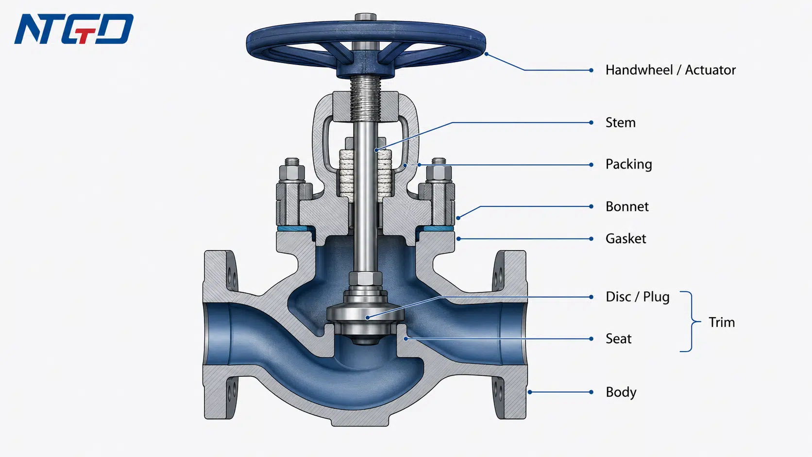
The main parts of a globe valve usually include:
- Body — the pressure-containing shell and flow passage.
- Bonnet — the cover that supports the stem and provides access to internal parts.
- Disc or plug — the movable closure element.
- Seat — the stationary sealing surface.
- Stem — the shaft that transfers motion from the handwheel or actuator to the disc.
- Packing — the stem sealing material that helps control external leakage.
- Gasket — the sealing element between body and bonnet or other joint surfaces.
- Trim — the internal wetted parts that strongly affect shutoff, flow control, and wear behavior.
- Handwheel or actuator — the operating device used to move the stem.
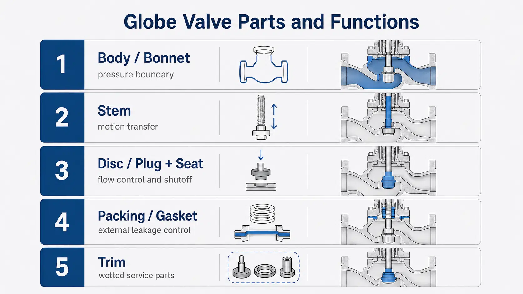
These parts can be grouped by engineering function: pressure boundary components, motion and flow-control components, sealing components, and operation interfaces. The diagram and table below follow this logic so the reader can move from part names to specification checks.
In many simplified explanations, a globe valve is described by only five parts: body, bonnet, stem, disc or plug, and seat. That is useful for a basic overview, but it is not enough for industrial selection. In real RFQs and maintenance discussions, packing, gasket, trim, and actuation details are also important.
What this article covers and what it does not cover
This article focuses on globe valve parts and function. It explains how the major components are arranged, what each part does, and why each part matters for service conditions and quotation.
It does not attempt to replace a full product datasheet, installation manual, or working-principle article. Topics such as globe valve flow direction, globe valve types, globe valve symbol, pressure drop calculation, standards, and material selection are only mentioned where they help explain the parts. Those topics normally require separate pages or product-specific documentation.
The goal is to help readers identify the main components quickly, understand their function, and avoid missing key RFQ details before discussing a valve specification.
Globe Valve Parts Diagram: How the Components Fit Together
A globe valve parts diagram should show how the pressure boundary, moving parts, sealing parts, and operating parts connect inside the valve.
A useful globe valve diagram with parts should not be just a generic drawing. It should clearly label the components that an engineer or buyer needs to identify during selection, inspection, or maintenance.
Main labels to show in the diagram
A clear labeled diagram should include at least these parts:
| Diagram Label | What It Helps the Reader Identify |
|---|---|
| Body | Main pressure-containing casting or forging and internal flow passage |
| Bonnet | Upper cover and stem-support area |
| Handwheel or actuator | Manual or automated operating device |
| Stem | Motion-transfer component connected to the disc or plug |
| Disc or plug | Movable closure element |
| Seat | Stationary sealing surface inside the body |
| Packing | Stem sealing area around the stem |
| Gasket | Body-bonnet joint sealing element |
| Trim | Internal wetted parts, usually including disc/plug, seat, stem, and related sealing/control components |
A strong diagram should also make the component relationship clear: the handwheel or actuator moves the stem; the stem moves the disc or plug; the disc or plug approaches or leaves the seat; and the body contains the flow path.
The following sections explain these labels in three engineering groups: pressure boundary components, motion and flow-control components, and sealing components.
For a product-specific structural example, NTGD’s flange globe valve structure page shows how body, stem, disc and seat details are handled when the valve design is tied to a flanged configuration.
How to read the diagram without confusing it with a full working-principle guide
The purpose of the diagram in this article is to identify parts and show their relationship. It should not turn the article into a complete “how does a globe valve work” guide.
When reading the diagram, focus on three layers:
- Pressure boundary — identifies which parts contain internal pressure and define the main valve envelope.
- Motion and control path — shows how operating input reaches the disc or plug.
- Sealing path — shows where internal shutoff and external leakage control depend on seat, packing, and gasket details.
Used together with the parts table, the diagram becomes a quick fit-check tool before reviewing material, trim, packing, gasket, and actuation requirements.
Globe Valve Parts and Functions Table
Main parts list
The following table summarizes the main globe valve parts, their functions, engineering impact, and maintenance or RFQ relevance.
| Part / Component | Main Function | Engineering Impact | Maintenance / RFQ Note |
|---|---|---|---|
| Body | Contains pressure and directs flow through the valve | Affects pressure boundary, flow path, end connection, and installation envelope | Confirm body material, pressure class, end connection, and body pattern |
| Bonnet | Covers the valve body and supports stem assembly | Affects pressure boundary, access to internals, and maintenance method | Confirm bonnet type and body-bonnet joint design |
| Disc / Plug | Moves toward or away from the seat to regulate or stop flow | Affects shutoff, throttling behavior, wear, and sealing contact | Confirm disc/plug design, material, and service suitability |
| Seat | Provides the fixed sealing surface | Affects leakage control, wear resistance, and shutoff reliability | Confirm seat material, seat design, and compatibility with media |
| Stem | Transfers motion from operating device to disc/plug | Affects operation, alignment, torque, and control stability | Confirm stem material, thread design, and actuation interface |
| Packing | Seals around the stem to reduce external leakage | Affects fugitive leakage, maintenance frequency, and safety review | Confirm packing material and service suitability |
| Gasket | Seals body-bonnet or other joint surfaces | Affects external leakage and joint reliability | Confirm gasket material and compatibility with temperature, pressure, and media |
| Trim | Group of internal wetted parts that affect control and sealing | Affects wear, corrosion resistance, shutoff, and service life | Confirm trim material and whether trim details match service conditions |
| Handwheel / Actuator | Provides manual or automated valve operation | Affects operating force, automation, and control response | Confirm manual operation, gearbox, pneumatic, electric, or other actuation needs |
Function, engineering impact and RFQ relevance
Unlike a basic parts list, this table connects each component to its engineering impact and quotation relevance. It helps buyers see which specifications must be confirmed early, such as pressure boundary details, disc-seat compatibility, packing and gasket requirements, trim scope, and actuation method, before a supplier makes assumptions during quotation.
For industrial valve selection, this is the difference between naming parts and controlling specification risk. A part name identifies the component. A function note explains what it does. An RFQ note tells the buyer what must be confirmed before that component can be treated as suitable for the service.
Pressure Boundary Components: Body, Bonnet and Gasket
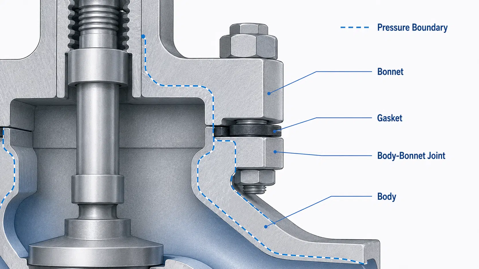
Pressure boundary components are the parts that help contain internal pressure and protect the valve from external leakage at major joints. In a globe valve, the most important pressure boundary parts are the body, bonnet, and gasket.
Body
The body is the main pressure-containing part of the globe valve. It houses the internal flow passage, supports the seat area, and provides the connection to the pipeline.
In many globe valve designs, the body creates a more indirect flow path than a straight-through isolation valve. This internal path helps the valve regulate flow but can also increase flow resistance. The exact body design depends on the valve type, size, pressure class, material, and service requirements.
When reviewing the body, buyers should confirm:
- body material;
- end connection;
- pressure class or pressure rating basis;
- body pattern or flow path;
- face-to-face or installation envelope if required by the project;
- whether the design is suitable for the intended media.
The body should not be treated as only an outer shell. It is one of the most important components for pressure boundary, flow path, and installation compatibility.
If the body pattern or material is not confirmed correctly, the valve may meet the size requirement but still fail the service, installation, or pressure-boundary requirement.
Bonnet
The bonnet is the cover attached to the valve body. It provides access to internal parts and supports the stem and packing area. Depending on the design, the bonnet may be bolted, welded, screwed, pressure-seal, or otherwise configured.
For maintenance, the bonnet is important because it often affects how internal parts are accessed. For selection, it matters because the bonnet connection influences sealing, assembly, and service suitability.
When reviewing the bonnet, confirm:
- bonnet construction;
- body-bonnet joint type;
- compatibility with pressure and temperature requirements;
- maintenance access;
- whether the design matches project specifications.
The bonnet should not be selected only by appearance. Its joint design and service suitability can affect leakage control and maintenance planning.
For services where maintenance access or external leakage control is important, bonnet design should be reviewed before the valve is treated as interchangeable with another globe valve.
Gasket and bonnet joint
The gasket helps seal the joint between pressure-containing parts, such as the body and bonnet. In many industrial globe valves, gasket material and joint design must match the service conditions.
A gasket problem can lead to external leakage, especially if the material, joint design, or service conditions are not suitable. For RFQ, gasket details may be important when the valve is used in steam, chemical, high-temperature, or high-pressure service.
The gasket should be reviewed together with the body-bonnet joint, not as an isolated consumable item. A valve body and bonnet may look suitable from the outside, but the joint sealing arrangement still needs to match the pressure, temperature, and media requirements.
Motion and Flow-Control Components: Handwheel, Actuator, Stem and Disc / Plug
The motion and flow-control components transfer operating input into valve movement. In a manual valve, the operator turns the handwheel. In an automated valve, the actuator provides the movement. That motion is transferred through the stem to the disc or plug.
Handwheel or actuator
The handwheel is the common manual operating device for many globe valves. It allows the operator to raise or lower the stem gradually. This controlled movement is one reason globe valves are often used where regulation is required.
An actuator may be used when the valve must be operated remotely, frequently, or as part of a control system. The actuator type depends on project requirements and valve design.
When confirming the operating method, check:
- manual or automated operation;
- handwheel, gear operator, pneumatic actuator, electric actuator, or other actuation;
- operating torque or thrust requirements;
- available installation space;
- control requirements.
The operating device should not be selected after the valve body is already finalized. Operation method can affect stem design, bonnet arrangement, and overall valve selection.
Selecting the operating method too late can lead to actuator mismatch, longer modification time, or poor operating response after installation.
Stem
The stem transfers motion from the handwheel or actuator to the disc or plug. In a globe valve, stem movement is typically linear. As the stem moves, the disc or plug moves toward or away from the seat.
The stem affects:
- operation smoothness;
- alignment between disc and seat;
- stem sealing through the packing area;
- manual torque or actuator sizing;
- service life under frequent operation.
Stem material and design should be compatible with the valve’s pressure, temperature, media, and operating frequency. For automated service, stem design and actuator interface should be confirmed early.
Disc or plug
The disc or plug is the movable closure element inside the globe valve. It moves against or away from the seat to control flow.
In simple terms:
- when the disc/plug moves toward the seat, flow is reduced;
- when it contacts the seat, the valve approaches shutoff;
- when it moves away from the seat, flow area increases.
The disc or plug affects shutoff behavior, throttling performance, wear pattern, and maintenance requirements. Different disc or plug designs may be used depending on service conditions.
For RFQ, the disc or plug should be confirmed together with the seat and trim material. A valve that looks correct externally may still be unsuitable if the internal closure element is not matched to the media, temperature, pressure, and control requirement.
Sealing Components: Seat, Disc Surface, Packing and Trim
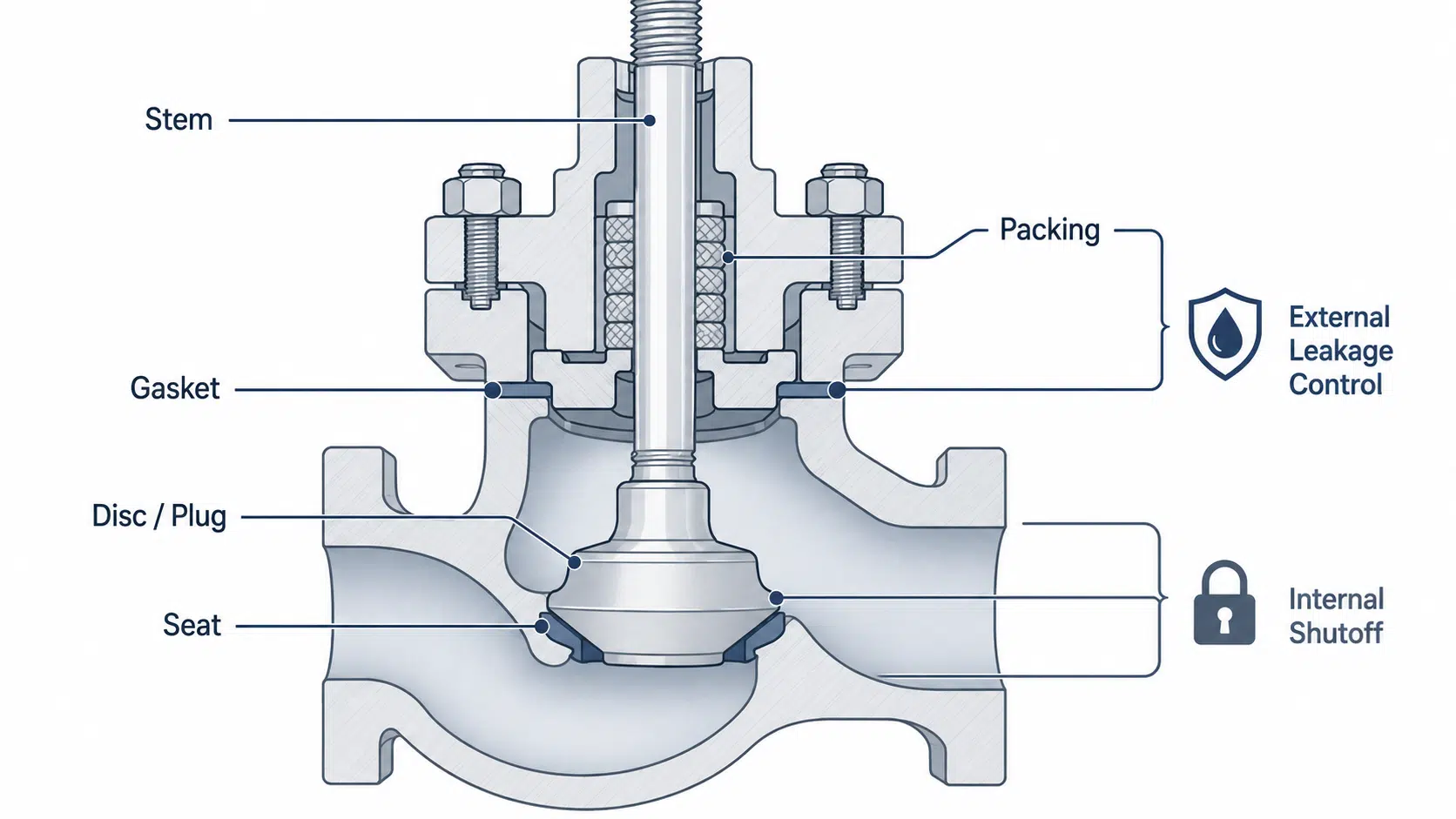
Sealing components determine whether the valve can shut off reliably and control external leakage. In a globe valve, internal sealing usually depends on the relationship between the disc or plug and the seat. External stem sealing depends strongly on the packing. Joint sealing depends on the gasket.
Seat
The seat is the stationary sealing surface inside the valve body. The disc or plug moves against the seat to restrict or stop flow.
The seat affects:
- shutoff performance;
- wear resistance;
- throttling behavior;
- compatibility with media;
- maintenance and replacement considerations.
Seat material and design must be reviewed according to service conditions. Abrasive, corrosive, high-temperature, or frequently throttled service can place different demands on the seat.
A globe valve seat should not be selected only by standard naming. The seat must be considered together with the disc or plug, trim material, leakage requirement, and service conditions.
When the main question becomes soft seat, metal seat or disc-seat material matching, review NTGD’s globe valve seat material selection guide instead of treating seat material as a simple parts-list item.
Disc-seat sealing interface
The disc-seat interface is one of the most important functional areas in a globe valve. This interface controls the internal closure point.
If the disc and seat are not suitable for the media or operating pattern, the valve may experience poor shutoff, unstable control, erosion, or accelerated wear.
Important checks include:
- sealing surface material;
- disc and seat compatibility;
- expected throttling duty;
- particulate or abrasive media;
- required shutoff level;
- maintenance access.
The disc-seat interface is also where many simplified explanations are too shallow. It is not enough to say “the disc closes the valve.” The real question is whether the disc and seat design are suitable for the actual operating conditions.
Packing
Packing seals around the stem and helps control leakage to the atmosphere. Because the stem moves during operation, packing must provide sealing while allowing the stem to move.
Packing selection can affect:
- fugitive emission control;
- maintenance frequency;
- operation friction;
- temperature compatibility;
- media compatibility;
- safety and environmental review.
Packing is often overlooked in basic globe valve parts descriptions, but it is important in real industrial service. For steam, chemical, thermal oil, gas, or hazardous media, packing details should not be left vague in the RFQ.
When packing is not matched to service temperature, media, or operating frequency, the valve may still operate normally but create repeated stem-leakage maintenance issues.
For emission-sensitive service, EPA equipment leak guidance notes that worn valve stem seals and packing can contribute to fugitive emissions from valves.
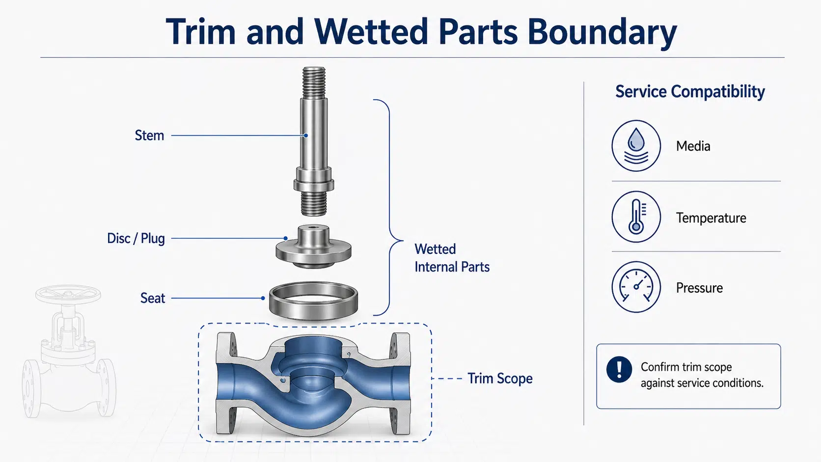
Trim as a specification-sensitive group
Trim is not always used consistently across suppliers, so it should be clarified during quotation. In many valve contexts, trim refers to internal wetted parts that affect flow control and sealing, such as the stem, seat, disc/plug, and related internal components.
Trim matters because it can influence:
- corrosion resistance;
- erosion resistance;
- shutoff;
- throttling behavior;
- maintenance interval;
- service life.
However, trim definitions can vary between suppliers, so the exact trim scope should be confirmed during quotation. Trim material mismatch can lead to corrosion, erosion, poor shutoff, or reduced service life, so trim should be checked against the actual media, temperature, and pressure instead of assumed from a general parts list.
For this article, trim is treated as a specification-sensitive group, not as a separate full material guide. A detailed trim selection article should handle material combinations, service media, temperature, pressure, and wear conditions in greater depth.
How Globe Valve Parts Work Together During Flow Control
Basic movement sequence
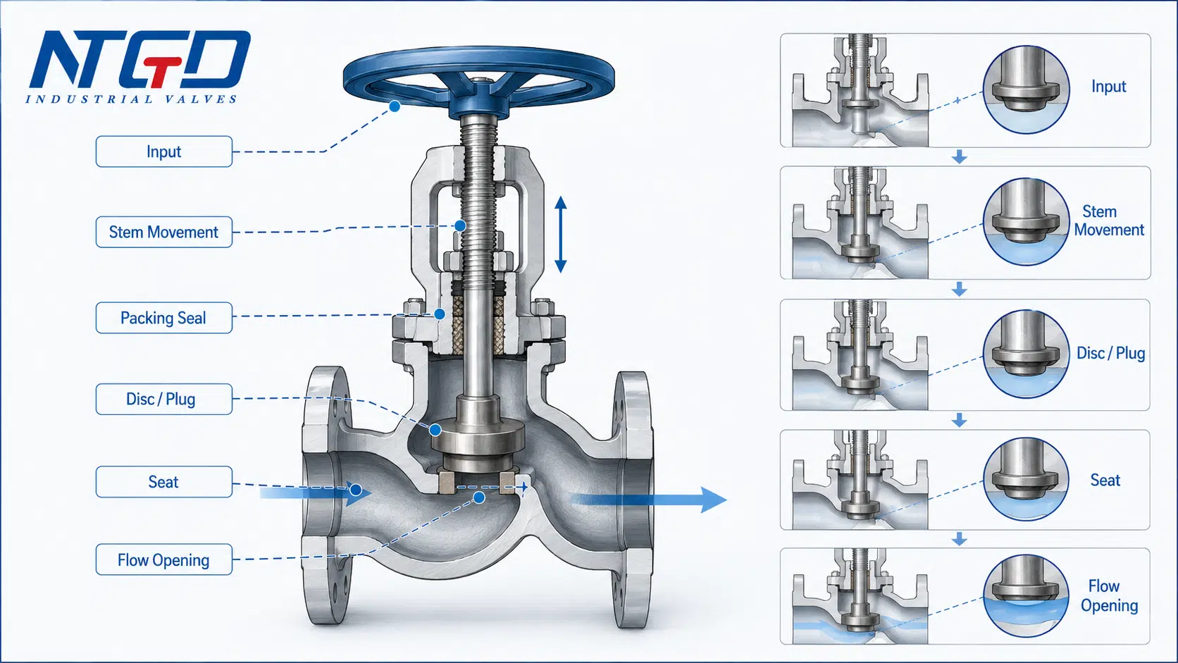
Globe valve parts work together through a linear motion sequence: the operating device moves the stem, and the stem positions the disc or plug relative to the seat to control the flow opening. The body contains the flow path, while packing and gaskets maintain external sealing during operation.
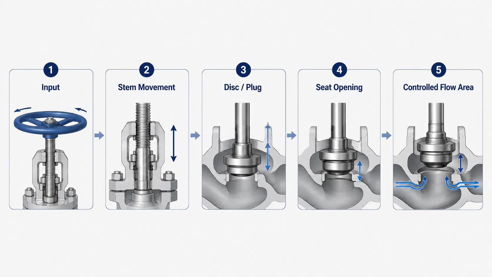
This sequence explains why globe valves are often used where flow regulation is needed. The disc or plug can be positioned at different openings, instead of only fully open or fully closed.
The animation below provides a simple visual reference for how the stem, disc or plug, seat and flow opening work together inside a globe valve.
Why this is only a working bridge, not a full working-principle section
This section only explains how the parts work together at a basic level. A full globe valve working-principle guide would need to discuss flow characteristics, plug design, pressure drop, throttling conditions, actuator behavior, cavitation risk, and control requirements in more detail.
For the purpose of this parts guide, the important point is simple: the component arrangement determines how the valve controls flow and how the valve should be specified.
This is enough for a parts guide; detailed flow characteristics, actuator behavior, pressure-drop analysis, and installation direction should be reviewed in separate technical pages.
Flow direction and pressure-drop caveat
Many globe valves are directional or have a recommended flow direction. The correct direction should be confirmed from the valve body marking, datasheet, manufacturer instructions, and project specification.
Globe valves may also create higher flow resistance than some straight-through isolation valves because of their internal flow path.
For general pressure-loss context, Engineering ToolBox minor loss data lists a fully open globe valve with a higher minor loss coefficient than fully open gate or ball valves, which supports checking pressure drop instead of assuming all valve bodies behave the same. This does not make them unsuitable; it means the valve should be selected with the required flow rate, pressure drop, service conditions, and control purpose in mind.
If a marked flow direction is ignored, the disc-seat interface, shutoff behavior, or operating stability may be affected, especially in throttling service.
Flow direction and pressure drop are important topics, but they should not dominate this parts article. They are best handled as separate technical topics when detailed installation or sizing guidance is required.
Engineering and Maintenance Implications of Key Globe Valve Components
Understanding globe valve components helps buyers and maintenance teams ask better questions before ordering, installing, or inspecting a valve.
For detailed inspection steps, leakage diagnosis and repair-or-replace decisions, use NTGD’s globe valve maintenance and troubleshooting guide instead of expanding maintenance procedures inside this parts guide.
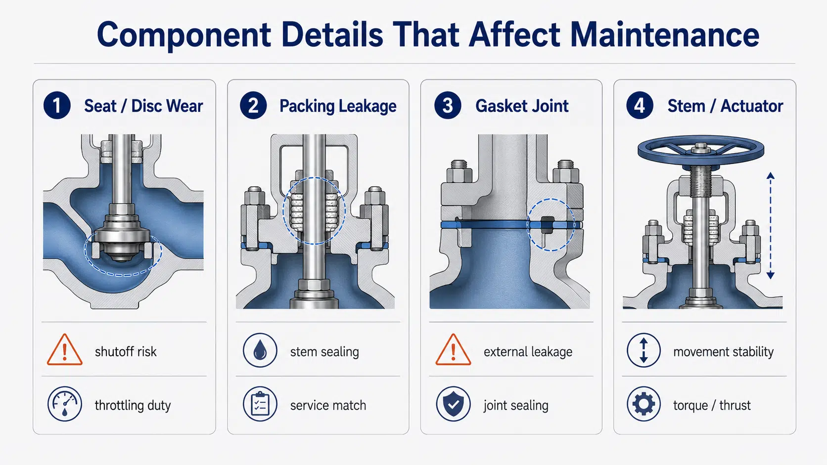
Seat and disc wear
Seat and disc surfaces are exposed to repeated contact and flow forces. In throttling service, the disc-seat area may experience more wear than in simple open/close operation.
Possible concerns include:
- leakage due to worn sealing surfaces;
- erosion from high-velocity or abrasive media;
- unstable shutoff after repeated operation;
- mismatch between trim material and service media.
Inspection and maintenance planning should pay attention to the seat and disc interface, especially in severe or frequently regulated service.
Stem alignment and operation feel
The stem affects the movement path of the disc or plug. Poor alignment, thread damage, contamination, or improper actuation can affect operation feel and sealing consistency.
A valve that becomes difficult to operate may indicate issues such as:
- packing friction;
- stem thread wear;
- misalignment;
- internal obstruction;
- actuator thrust or torque mismatch causing incomplete movement or unstable control.
The stem should be reviewed together with the packing, bonnet support, disc connection, and operating method.
Packing leakage and gasket sealing
Packing and gasket issues are common reasons for external leakage review.
Packing leakage is related to the stem sealing area. Gasket leakage is related to joint sealing, such as the body-bonnet joint. These are different leakage paths and should not be treated as the same problem.
When leakage control is important, confirm:
- packing material;
- gasket material;
- service temperature and media;
- operating frequency;
- applicable project leakage requirement;
- maintenance access.
The correct choice depends on the valve design and service conditions.
When component details should be checked before replacement or quotation
This article is not a spare parts sales page, but component details are still important when discussing replacement or quotation.
Before requesting a quotation, confirm whether the requirement is for:
- a complete new globe valve;
- replacement internal trim;
- maintenance parts;
- packing or gasket review;
- actuation change;
- service-specific material upgrade.
Different requests require different information. A vague RFQ such as “globe valve parts” may not be enough for accurate supplier selection.
If the request involves leakage, repeated operation, throttling service, or media compatibility, the component detail should be clarified before the RFQ is issued. This allows the RFQ checklist in the next section to function as a specification control tool, not only a purchasing form.
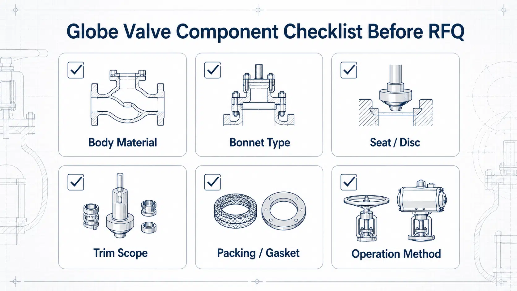
What to Confirm Before RFQ: Globe Valve Component Checklist
A good RFQ should not only ask for a globe valve size and pressure class. It should also clarify the key components that affect service suitability.
| Item to Confirm | Related Part | Why It Matters | What to Ask Supplier |
|---|---|---|---|
| Body material and end connection | Body | Affects pressure boundary, corrosion resistance, and installation | What body material and end connection are recommended for the service? |
| Bonnet design | Bonnet | Affects pressure boundary and maintenance access | What bonnet type is supplied for this design and service? |
| Seat and disc design | Seat, disc/plug | Affects shutoff, throttling, and wear | What seat and disc materials are used? Are they suitable for the media? |
| Trim material | Trim | Affects corrosion, erosion, sealing, and service life | Which parts are included in the trim specification, and are they suitable for the actual media and operating pattern? |
| Packing material | Packing | Affects stem leakage and operation | What packing material is recommended for the service temperature and media? |
| Gasket material | Gasket | Affects body-bonnet joint sealing | What gasket material is used for the body-bonnet joint? |
| Operation method | Handwheel / actuator | Affects operation force and automation | Is manual operation suitable, or is an actuator required? |
| Flow direction requirement | Body / disc-seat arrangement | Affects installation direction, disc-seat contact, and shutoff reliability | Is there a marked or recommended flow direction? |
| Maintenance access | Bonnet / trim / packing | Affects inspection and downtime | How are internal parts and packing accessed? |
| Service conditions | All wetted and sealing parts | Determines material and design suitability | What media, pressure, temperature, and operating pattern should be considered? |
This checklist helps prevent supplier assumptions. It also helps ensure that the quoted valve matches the actual operating conditions, not just the nominal valve size.
The checklist is most useful when it is completed before supplier quotation, because it reduces assumptions about internal parts that may not be visible from the valve model or size alone.
If the RFQ question expands from component confirmation to overall valve-type selection, refer to NTGD’s industrial valve selection guide before comparing globe valves with other valve types.
Related Globe Valve Topics and Product Page Boundaries
When to review globe valve type, flow direction or working principle separately
Some related topics are important but should not be expanded inside this article.
Review a separate globe valve working principle guide when the main question is how the valve regulates flow, how the disc and seat interact through different positions, or why pressure drop occurs.
Review a globe valve flow direction guide when the main question is installation direction, body arrow, flow under or over the disc, or consequences of installing the valve incorrectly.
Review a globe valve types guide when the main question is the difference between T-pattern, Y-pattern, angle-pattern, or other structural forms.
For broader body-pattern comparison and selection boundaries, see NTGD’s globe valve types and selection guide.
Review a globe valve symbol guide when the main question is P&ID representation, not physical components.
Flow direction, working principle, valve-type selection and material limits are related topics, but they should be reviewed on separate technical pages when they become the main engineering question.
When to review product pages such as steam or high-pressure globe valves
This article explains general globe valve parts and components. Product pages should be reviewed when the requirement becomes service-specific.
For example:
- Steam globe valves may require special review of body material, gasket, packing, seat, disc, and service temperature because steam service can place combined thermal, pressure, and sealing demands on multiple components at the same time. For service-specific configuration details, review NTGD’s steam globe valve page rather than treating steam service as a generic parts-list issue.
- High-pressure globe valves may require closer review of body-bonnet design, pressure boundary, trim, and applicable project specification. For high-pressure service, NTGD’s high pressure globe valve structure page is the better place to review pressure-boundary and component-level design details.
- Cryogenic or chemical service may require material and sealing compatibility review beyond a general parts guide.
The general parts guide helps define the technical questions. Product pages, datasheets, and supplier confirmation should answer the project-specific requirements.
FAQ About Globe Valve Parts and Components
What are the parts of a globe valve?
The main parts of a globe valve usually include the body, bonnet, disc or plug, seat, stem, packing, gasket, trim, and handwheel or actuator. In a simplified list, the five main parts are often body, bonnet, stem, disc or plug, and seat.
What are the components of a globe valve?
Globe valve components can be grouped by function: pressure boundary components such as the body and bonnet, motion components such as the handwheel and stem, flow-control components such as the disc or plug and seat, and sealing components such as packing and gasket. This grouping helps buyers understand which parts affect pressure containment, flow regulation, and leakage control.
What are the 5 main parts of a globe valve?
The five main parts are commonly listed as body, bonnet, stem, disc or plug, and seat. However, for industrial selection, packing, gasket, trim, and actuation details should also be reviewed because they affect sealing, leakage control, maintenance, and RFQ accuracy.
What is the difference between globe valve parts and trim?
Globe valve parts refer to all major components of the valve, including the body, bonnet, stem, disc, seat, packing, gasket, and operating device. Trim usually refers to internal wetted parts that affect flow control and sealing, such as the stem, disc or plug, seat, and related internal components. The exact trim definition should be confirmed with the supplier.
How do globe valve parts work together?
The handwheel or actuator moves the stem. The stem moves the disc or plug toward or away from the seat. This changes the flow area inside the body. Packing seals around the moving stem, while the bonnet and gasket help maintain the pressure boundary. This sequence is why the stem, disc or plug, and seat should be specified together rather than treated as unrelated parts.
Why are packing and gasket important in a globe valve?
Packing helps seal around the stem and reduce external leakage from the stem area. The gasket helps seal the body-bonnet joint or other joint surfaces. Both are important for leakage control, maintenance planning, and service compatibility. In services such as steam, chemicals, thermal oil, or hazardous media, packing and gasket material should match service conditions rather than be assumed from a standard component list.
Conclusion
Globe valve parts should be understood as a working system, not as isolated names. The body and bonnet form the pressure boundary. The handwheel or actuator, stem, and disc or plug create movement. The seat, disc surface, packing, gasket, and trim control sealing, leakage, wear, and service suitability.
For a basic overview, it may be enough to know the body, bonnet, stem, disc, and seat. For industrial selection and quotation, that is not enough. Buyers and engineers should also confirm packing, gasket, trim, actuation, body-bonnet design, seat/disc materials, and service conditions before finalizing a globe valve specification.
Using a structured parts identification approach—with a labeled diagram, a parts table, and a specification checklist—helps engineering, procurement, and suppliers work with the same component references before the valve is selected or quoted.
Application / Specification Support
For industrial globe valve selection, confirm the valve size, pressure class, body material, trim material, seat and disc design, bonnet type, packing, gasket, end connection, operation method, media, temperature, pressure, and required shutoff performance before quotation.
For product-level selection context, review NTGD’s globe valve page before finalizing the valve type and quotation scope.
NTGD supports globe valve selection by confirming component details against service conditions before the RFQ is finalized, especially when packing, gasket, trim, or actuation requirements may affect the quotation.
To send service conditions for review, use the NTGD contact page and include media, pressure, temperature, size, end connection, operation method and leakage expectations.
For service-specific designs such as steam, high-pressure, chemical, or general industrial applications, the component details should be checked before the quotation is finalized.
