Author Name: Bruce Zheng
Author Role: Co-Founder and Valve Engineer at NTGD Valve
Author Bio: Bruce Zheng is Co-Founder and Valve Engineer at NTGD Valve, focusing on industrial valve selection, application, and technical content for global B2B buyers.
Last Updated: June 2, 2026
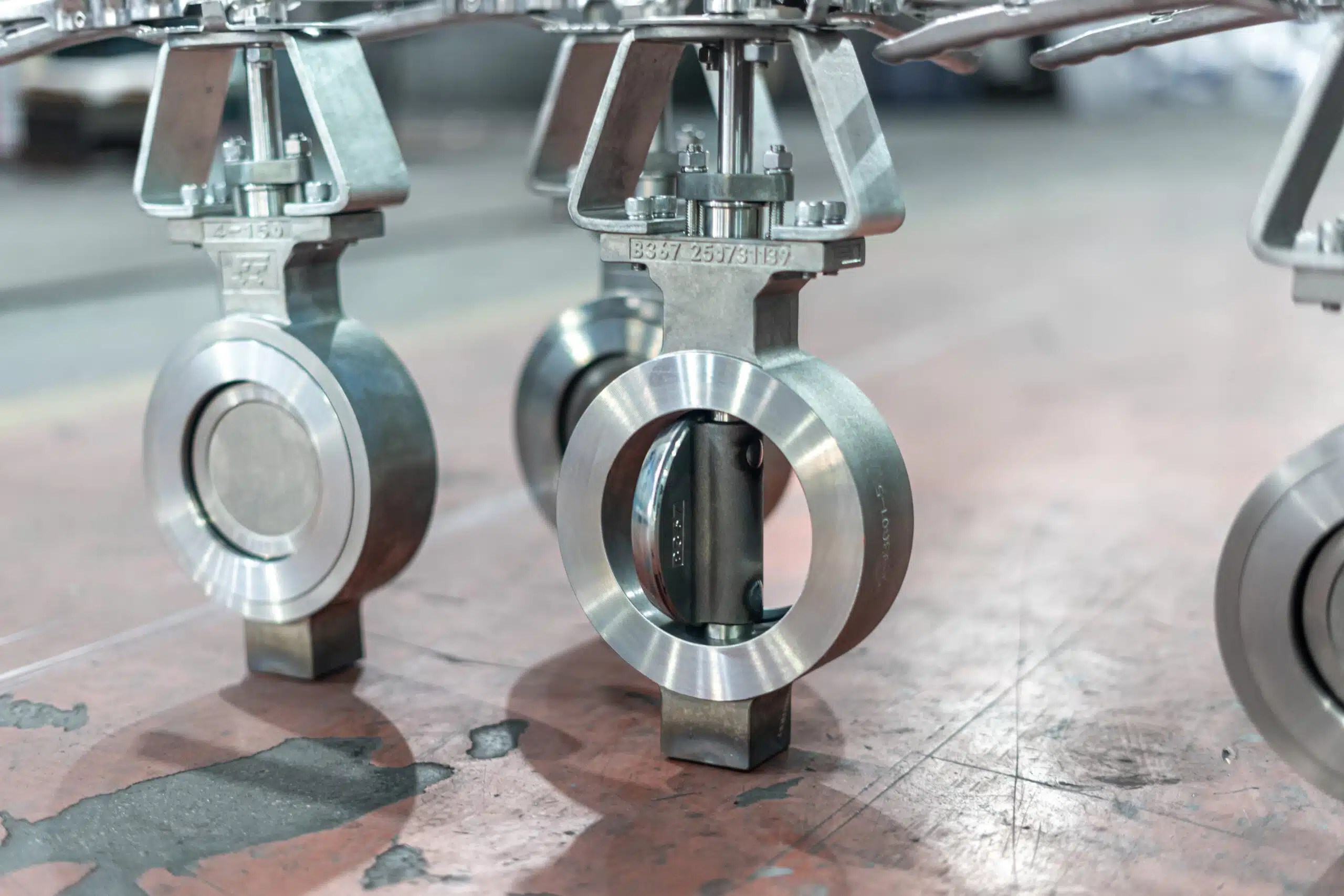
Butterfly valve parts are not only names on a drawing. In industrial service, the body, disc, stem, seat, seals, actuator and support components all affect shutoff performance, torque, leakage control, corrosion resistance and RFQ accuracy.
A butterfly valve is a quarter-turn valve. Its disc rotates inside the valve body to open, throttle or close the flow path. The valve works reliably only when the main components are matched to the media, pressure, temperature, connection type, sealing requirement and actuation method.
This guide explains the main butterfly valve components, what each part does, how the parts work together, and which component details should be confirmed before sending an RFQ.
Quick Answer: What Are the Main Parts of a Butterfly Valve?
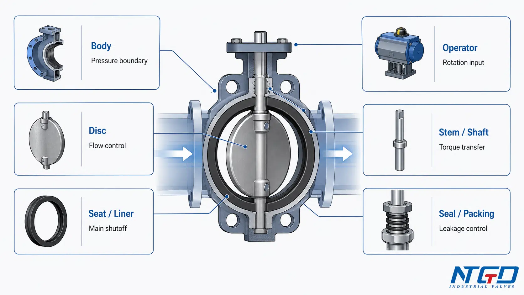
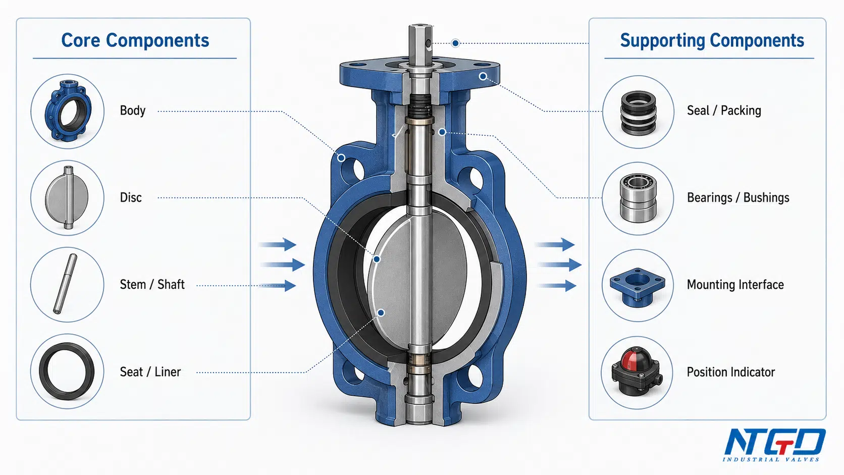
The main parts of a butterfly valve are the valve body, disc, stem or shaft, seat or liner, seals, and operator or actuator. Supporting components may include bearings, bushings, packing, gland seals, mounting hardware and position indicators.
In a typical butterfly valve:
- The body supports the valve structure and connects to the pipeline.
- The disc rotates to control or stop flow.
- The stem or shaft transfers torque from the operator to the disc.
- The seat or liner provides the main sealing contact surface.
- The seals and packing help prevent leakage through body and shaft interfaces.
- The operator or actuator drives the stem and disc.
- The bearings, bushings and support parts help maintain alignment and smooth rotation.
In this article, “butterfly valve parts” refers to the structural and functional components of an industrial butterfly valve. It does not refer to replacement part numbers, spare part kits, repair kits, SKU catalogs, stock availability, prices or seat replacement instructions.
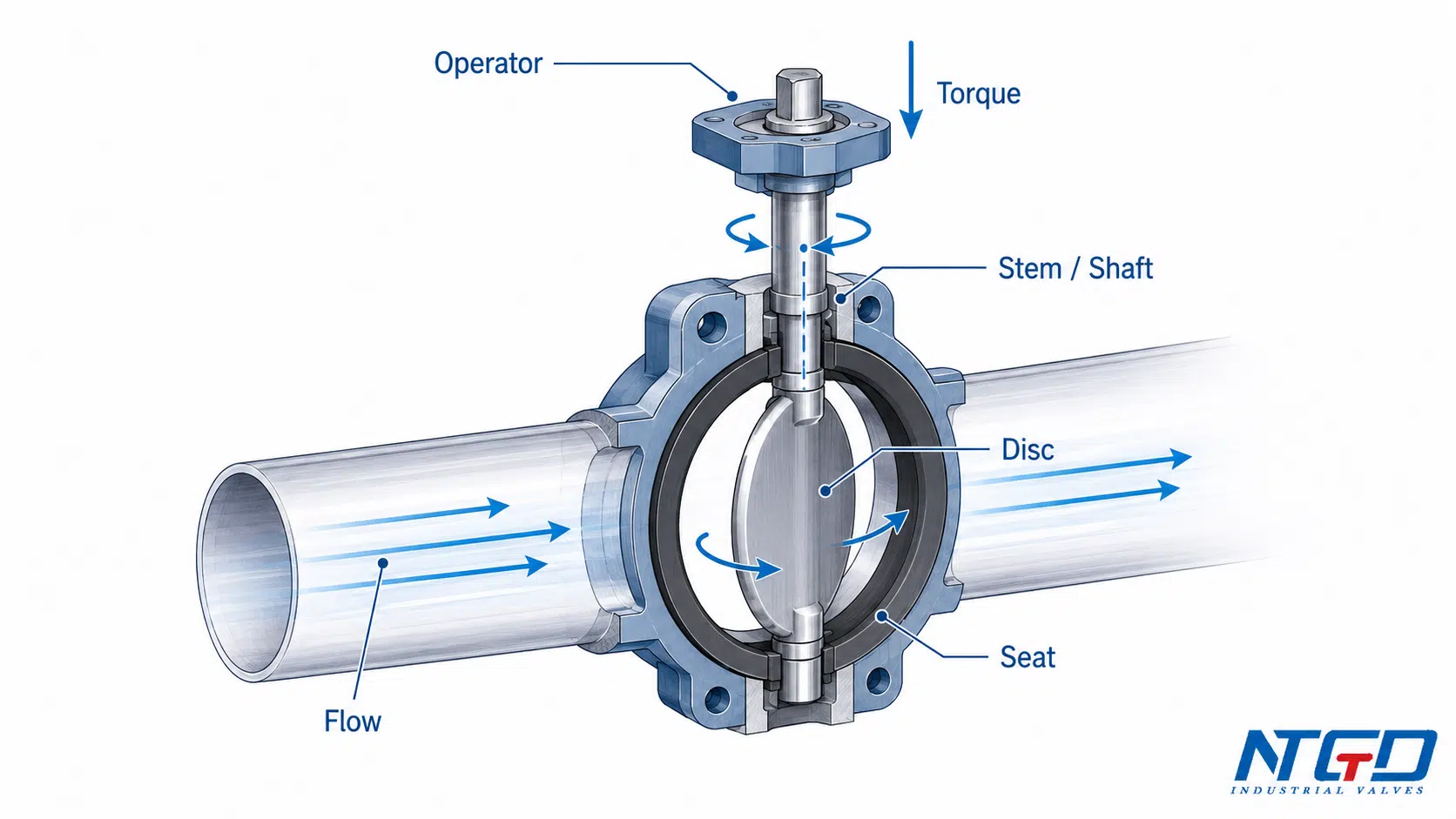
Butterfly Valve Parts Diagram: What Each Labeled Component Shows
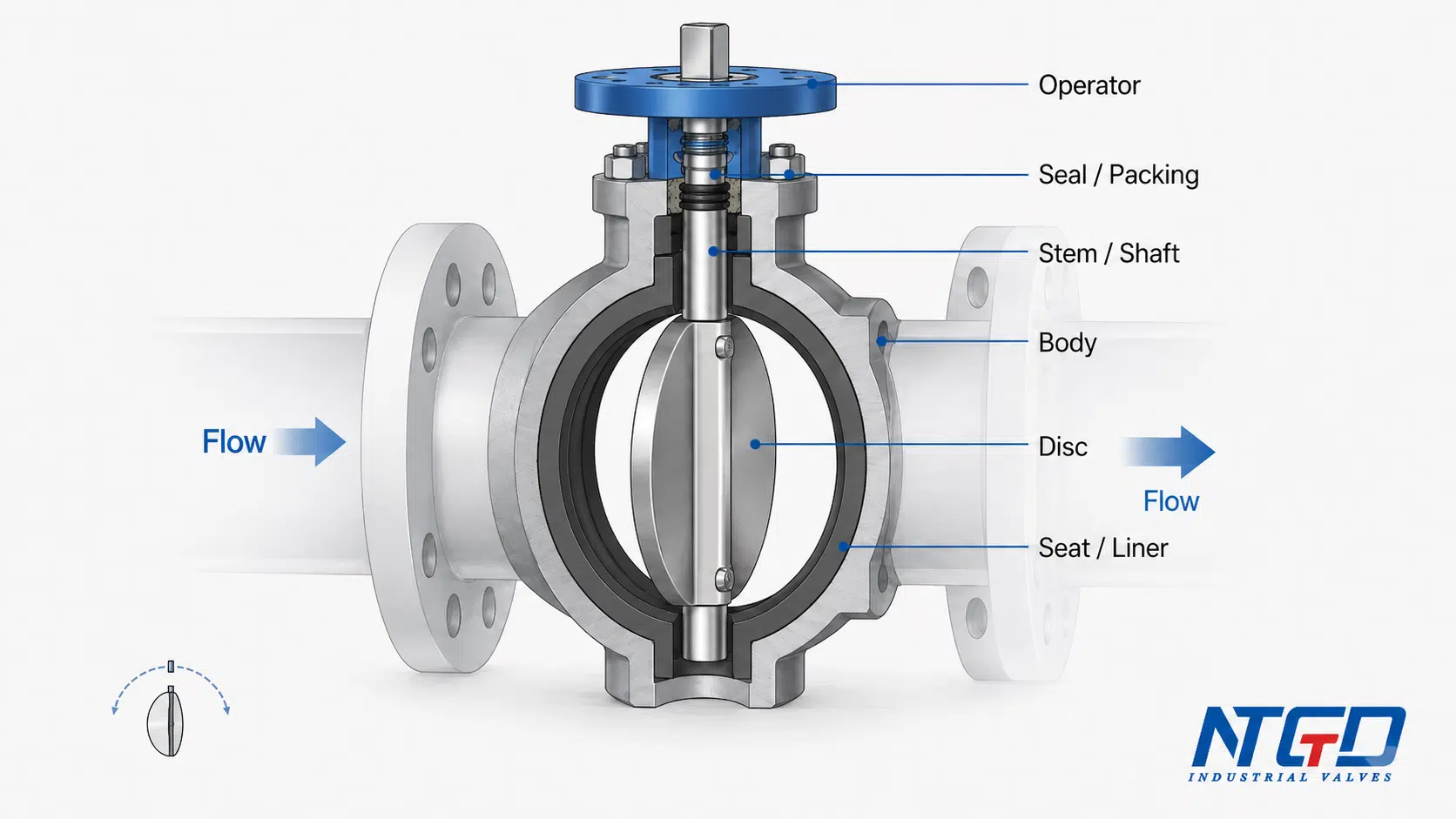
A butterfly valve parts diagram should show the relationship between the valve body, disc, stem, seat, seal and operator. The purpose of the diagram is not only to identify part names, but also to show how the valve opens, closes and seals.
A useful butterfly valve parts diagram should normally show:
- the valve body as the outer pressure-retaining structure;
- the disc positioned in the flow path;
- the stem or shaft passing through or connecting to the disc;
- the seat or liner around the disc sealing area;
- the shaft seal, packing or gland area near the stem penetration;
- the operator or actuator above or outside the body;
- the flow direction through the valve;
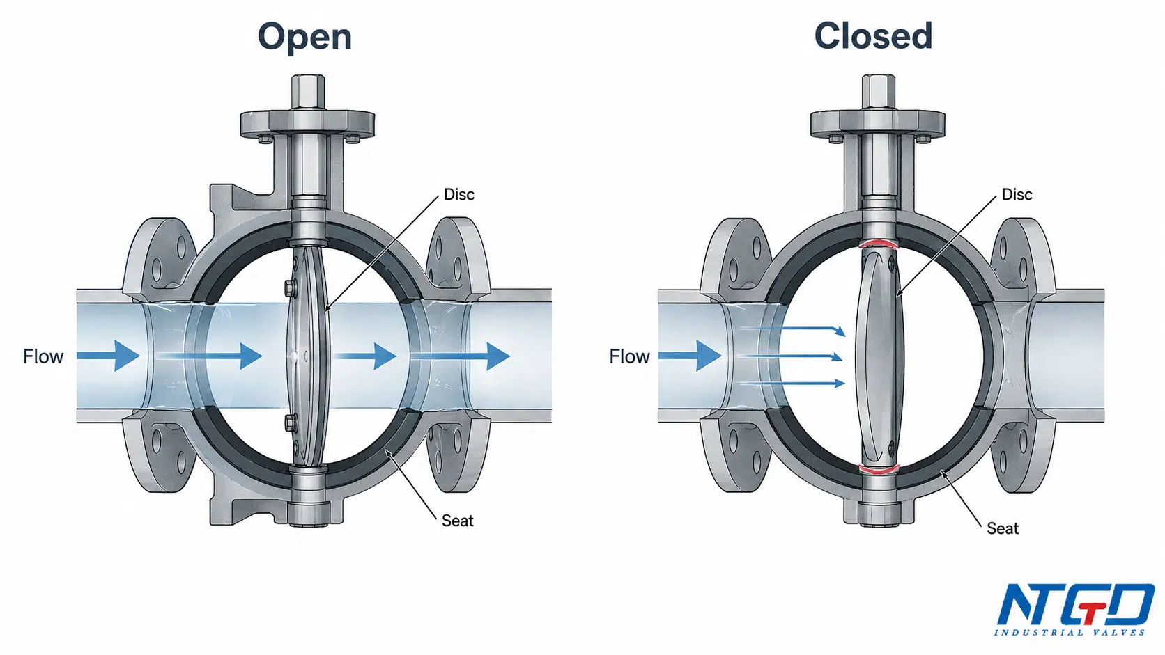
- the open and closed disc positions, if the diagram is explaining operation.
In the open position, the disc is turned toward the flow direction and leaves a larger flow opening. In the closed position, the disc turns across the flow path and contacts the seat or liner to form the main shutoff interface.
For a parts guide, the diagram should stay focused on structural components. It does not need to become a wiring diagram, a P&ID symbol guide, a complete actuator circuit or a spare parts catalog.
Main Butterfly Valve Parts and Their Functions
The following table summarizes the major butterfly valve components and why each one matters in industrial service.
| Part / Component | Main Function | Service Relevance | RFQ / Specification Note | Common Risk if Misapplied |
|---|---|---|---|---|
| Valve body | Holds the internal parts and connects the valve to the pipeline | Affects pressure boundary, installation style, flange fit and corrosion resistance | Confirm body style, connection type and body material | Wrong body style may create installation, flange compression or seat / liner support problems |
| Disc / disk | Rotates inside the flow path to open, throttle or close the valve | Affects flow control, shutoff, erosion resistance and wetted-part durability | Confirm disc material and service condition | Poor disc material, coating damage or disc edge wear can reduce shutoff performance |
| Stem / shaft | Transfers torque from the operator or actuator to the disc | Affects torque transmission, alignment, shaft sealing and operation reliability | Confirm shaft material and design if the service is corrosive, abrasive or severe | Misalignment, corrosion or insufficient shaft strength can cause high torque or uneven disc movement |
| Seat / liner | Provides the main disc sealing contact surface | Affects shutoff, internal leakage control, torque, temperature and media compatibility | Confirm seat / liner material and sealing requirement | Wrong seat material can swell, wear, harden or fail to seal against the disc |
| Seals / packing | Seal body joints and shaft penetration areas | Affects external leakage and long-term sealing reliability | Confirm shaft sealing arrangement where leakage risk is critical | Poor packing or seal condition can create leakage around body or stem interfaces |
| Operator / actuator | Drives the stem and disc | Affects operation method, torque delivery, control signal and feedback | Confirm manual, gearbox, pneumatic or electric operation | Undersized or unsuitable operation method can cause difficult or unreliable operation |
| Bearings / bushings | Support shaft rotation and help maintain alignment | Affects friction, torque consistency, shaft wear and disc-seat contact | Confirm suitability for operating frequency and service condition | Worn support parts can increase torque, shift disc alignment or accelerate seat wear |
| Gland area / shaft sealing area | Supports shaft sealing and packing compression | Affects leakage around the stem, especially in demanding media service | Confirm gland and packing arrangement if external leakage is a concern | Leakage around the stem area is more critical in hazardous, corrosive, regulated or high-pressure media service |
| Mounting interface | Connects actuator or operator to valve topworks | Affects actuator installation, alignment and torque transfer | Confirm mounting arrangement when automation is required | Poor mounting fit can affect actuator alignment, torque delivery and automation reliability |
| Position indicator | Shows open, closed or intermediate position | Supports operation checking, manual inspection and site control | Confirm if visual indication or feedback is needed | Operator may misread valve status without clear position indication or feedback |
This table is a structural guide, not a replacement parts catalog. Exact materials, dimensions and pressure-temperature limits should be checked against the project specification and manufacturer datasheet.
For formal project specifications, the valve configuration can also be checked against applicable butterfly valve standards such as API 609 for double-flanged, lug and wafer butterfly valves when required by the project.
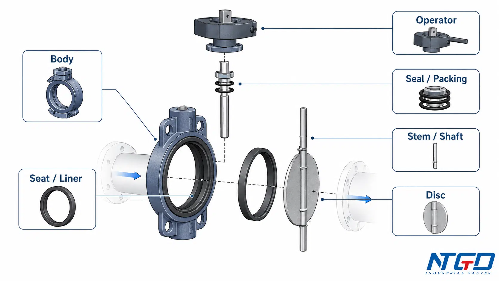
Core Structural Parts: Body, Disc, Stem and Seat
The core butterfly valve components are the body, disc, stem or shaft, and seat or liner. These parts form the basic mechanical and sealing structure of the valve.
Valve Body: Pressure Boundary and Connection Support
The valve body is the outer structure that holds the disc, seat, stem and sealing components in position. It also provides the connection between the valve and the pipeline.
In industrial service, the body affects more than installation. It influences pressure boundary integrity, flange compatibility, corrosion resistance and the space available for the internal sealing structure.
Common body-related design considerations include:
- whether the valve is installed as a wafer, lug or flanged design;
- whether the body material is suitable for the media and environment;
- whether the body style matches the pipeline flange and installation requirements;
- whether the internal body geometry supports the selected seat and disc design.
For compact installations where the valve body is clamped between pipeline flanges, review the wafer butterfly valve configuration as a body-style reference.
If downstream-side isolation or end-of-line handling is part of the specification, the lug butterfly valve page is a more suitable body-style reference.
The body section of a parts guide should not become a full butterfly valve types guide. Wafer, lug and flanged designs are important, but they are connection and product-page topics. In a parts article, they should be treated as body-related specification factors.
A wrong body connection style is not only an installation issue. It may affect flange fit, gasket compression, seat or liner support, actuator alignment and long-term sealing stability. If the body material is not suitable for the media or environment, the body-liner interface and pressure-retaining surfaces may also become reliability risks.
Disc / Disk: The Flow Control and Shutoff Element
The disc is the rotating closure member inside the butterfly valve. When the valve opens, the disc turns toward the flow direction. When the valve closes, the disc rotates across the flow path and contacts the seat or liner.
The disc affects:
- flow opening area;
- shutoff performance;
- media contact;
- erosion resistance;
- torque requirement;
- disc-seat wear pattern.
In many industrial applications, the disc is one of the main wetted parts. For corrosive, abrasive or temperature-sensitive services, disc material and surface condition must be checked carefully. A damaged disc edge, poor material match or incorrect disc-seat contact can reduce sealing performance.
In abrasive media, slurry service or high-velocity flow, the disc edge is often one of the most exposed wear areas. If the disc edge becomes damaged or uneven, the disc may no longer contact the seat consistently, which can affect shutoff performance and increase torque.
This article only explains the disc as a functional component. Full disc material selection, coating selection or offset disc design should be treated as separate product or technical selection topics.
Stem / Shaft: Torque Transfer Between Operator and Disc
The stem, also called the shaft, connects the disc to the operator or actuator. Its main function is torque transfer. When the handle, gearbox, pneumatic actuator or electric actuator moves, the stem transfers that motion to the disc.
The stem affects:
- operating torque;
- disc alignment;
- shaft sealing;
- long-term rotation stability;
- compatibility with actuator mounting;
- whether the shaft area is wetted or isolated from the media.
Some butterfly valve designs use a through shaft, split shaft or other shaft arrangements depending on the valve structure. For the buyer, the key point is not only the shaft name, but whether the shaft material, sealing arrangement and torque capacity match the service.
If the shaft material or surface condition is not suitable for wetted or corrosive service, the shaft sealing area may become vulnerable. Shaft misalignment, corrosion or surface damage can increase operating torque and reduce the accuracy of disc-seat contact.
Stem extension, gearbox spare parts and actuator accessories should not be treated as the main topic of a general butterfly valve parts guide. They are product-specific or actuation-specific topics.
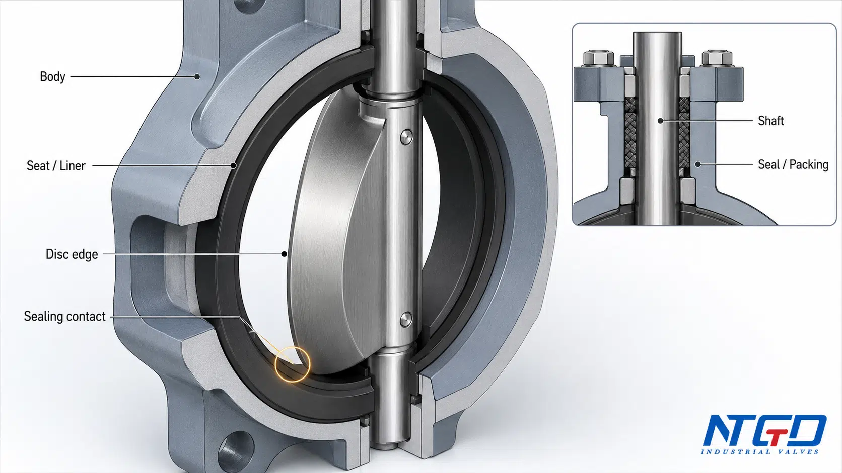
Seat / Liner: The Disc Contact Surface for Shutoff
The seat or liner is the main sealing contact surface between the valve body and the disc. When the disc closes, the disc edge presses against the seat or liner to help stop flow.
The seat affects:
- shutoff performance;
- internal leakage risk;
- torque;
- media compatibility;
- temperature suitability;
- wear resistance;
- whether the valve is better suited for soft-seated or metal-seated service.
Soft seats are commonly associated with resilient sealing. Metal seats are usually connected with higher temperature, severe service or high-performance designs, depending on the valve structure. The exact suitability depends on the manufacturer’s design, service condition and project specification.
In some butterfly valve designs, the liner works as an internal body lining or sealing sleeve, while the seat refers more directly to the disc contact sealing surface. In practice, seat and liner design often work together to control disc-seat sealing, body protection and media compatibility.
This article only covers the seat or liner as a butterfly valve component. Detailed seat material selection, soft seat versus metal seat comparison, booted or cartridge seat construction, and seat replacement steps belong in a dedicated butterfly valve seat selection or maintenance guide.
Sealing Structure: Seat, Liner, Seals, Packing and Gland Area
A butterfly valve does not seal through the seat alone. The seat or liner is the main disc contact area, but the overall sealing structure may also include shaft seals, body seals, packing, gland components and other sealing interfaces.
For specification work, it is not enough to specify only the seat material. Buyers should also confirm whether the shaft seal, packing, body seal and liner arrangement are compatible with the media, temperature, pressure, cycling frequency and leakage expectation.
The most important sealing zones are:
| Sealing Area | Related Parts | Main Purpose | Risk if Not Correctly Matched |
|---|---|---|---|
| Disc-to-seat contact | Disc edge, seat, liner | Controls internal shutoff | Internal leakage, poor shutoff, seat wear |
| Shaft penetration area | Stem / shaft, packing, gland seal | Helps prevent leakage around the stem | External leakage near the shaft |
| Body interface | Body, liner, body seals | Supports sealing between body and internal components | Leakage around body or liner area |
| Actuator / topworks interface | Stem, mounting interface, top flange | Maintains alignment between operation device and valve shaft | High torque, uneven movement or actuator misalignment |
Where pressure boundary integrity or closure tightness testing must be documented, confirm the testing requirement against ISO 5208:2015 for pressure testing of industrial metallic valves and the applicable valve product standard.
When the service requires metal-seat or severe-service sealing, compare the sealing geometry with NTGD’s triple offset butterfly valve configuration rather than expanding this seat section into a full selection guide.
The disc-seat interface is especially important. If the disc does not align correctly with the seat, or if the seat material is not suitable for the service, shutoff performance can be affected. In abrasive service, the disc edge and seat may wear. In chemical service, the seat and seal material must be checked for media compatibility. In higher-temperature service, seat design becomes even more critical.
Disc-seat leakage does not always come from the seat alone. It may also be connected to disc edge damage, stem alignment, bearing wear, actuator torque mismatch, or a body / liner fit that does not support stable sealing.
Packing and gland seals should also not be ignored. Even if the disc-seat shutoff is acceptable, leakage around the stem area can still be a problem if the shaft sealing arrangement is not suitable.
For specification work, buyers should not only ask for “a butterfly valve seat.” They should confirm media, temperature, pressure, shutoff expectation, actuation method and whether the service creates corrosion, abrasion or cycling concerns.
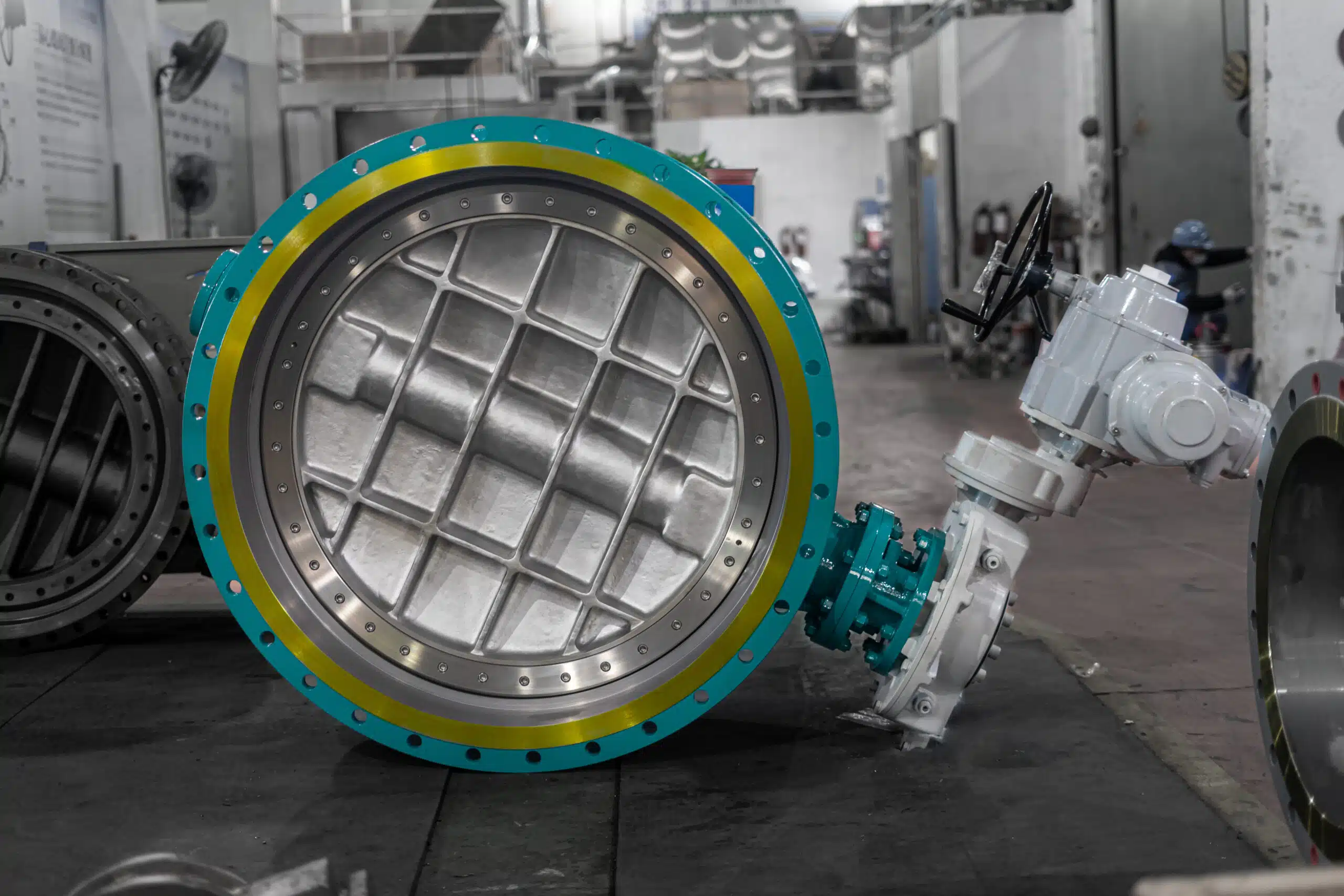
Operator, Actuator and Supporting Components
Butterfly valve components include more than the four basic structural parts. The operator, actuator, bearings, bushings, packing and mounting interface all influence how the valve performs in real pipeline service.
Operator / Actuator: Handle, Gearbox, Pneumatic and Electric Operation
The operator or actuator provides the force needed to rotate the stem and disc. Common operation methods include manual handle, gearbox, pneumatic actuator and electric actuator.
The internal operating logic remains similar:
> operator or actuator → stem / shaft → disc rotation → seat contact or flow opening
The difference is how torque is applied and controlled.
A manual handle may be suitable for small valves or low operating frequency. A gearbox can reduce manual effort for larger sizes or higher torque conditions. A pneumatic actuator is often used where fast operation or fail-position logic is required. An electric actuator may be selected where electrical control, position feedback or slower controlled movement is needed.
This section does not replace an actuator selection guide. Actuator sizing, fail position, control signal, feedback and site power or air supply must be checked against the project requirement and valve torque data. For automated valves, these details should be reviewed separately from the general parts list because they affect both operation reliability and control integration.
For air-operated automation requirements, keep this parts guide focused on the operator interface and review the pneumatic butterfly valve page for actuator-specific configuration.
For motor-driven operation, the electric actuated butterfly valve page is the more relevant product bridge.
Bearings and Bushings: Shaft Support and Rotation Stability
Bearings and bushings support the stem or shaft as it rotates. They help maintain alignment and reduce friction between moving parts.
Their role is easy to overlook, but they can affect:
- operating torque;
- disc alignment;
- shaft wear;
- actuator load;
- long-term cycling stability.
If bearings or bushings wear, the disc may not remain centered against the seat. That can increase torque and reduce sealing reliability. For high-cycle, abrasive or severe services, these support components should not be treated as minor details.
In RFQ review, bearings and bushings matter most when the valve will cycle frequently, handle abrasive media, or operate with an actuator that requires consistent torque response.
Packing, Gland Seal and Shaft Sealing Area
The packing or gland seal area helps control leakage where the stem passes through the valve body or topworks area. This area is separate from the disc-seat shutoff line.
A valve can have acceptable internal shutoff and still develop external leakage if the shaft sealing area is not suitable. This is why packing, gland design and shaft seal compatibility should be considered when the service involves hazardous, corrosive, hot or regulated media.
This article does not cover packing replacement procedures. The purpose here is to identify the component and explain why it matters during specification.
Mounting Interface and Position Indicator
The mounting interface connects the valve to the actuator or operator. If automation is required, this interface must support proper alignment between the actuator output and the valve stem.
A position indicator shows whether the valve is open, closed or partially open. For manual valves, this may be a simple mechanical indication. For automated valves, position feedback may be part of the control requirement.
These parts are not always the first items listed in a simple butterfly valve parts diagram, but they are important for operation, inspection and control integration. In automation projects, the buyer should confirm mounting compatibility, position feedback requirements and whether the actuator interface matches the valve torque and control strategy.
How Butterfly Valve Parts Work Together
A butterfly valve works through a simple quarter-turn motion, but the performance depends on how the parts interact.
When the operator applies torque, the stem or shaft rotates. The shaft turns the disc inside the valve body. As the disc moves toward the open position, the flow path becomes less restricted. As the disc moves toward the closed position, the disc edge contacts the seat or liner and forms the main shutoff interface.
In simplified form:
1. The operator or actuator applies torque. 2. The stem or shaft transfers the torque. 3. The disc rotates around the shaft axis. 4. The disc changes the flow opening. 5. In the closed position, the disc contacts the seat or liner. 6. Seals and packing protect shaft and body interfaces. 7. Bearings and bushings help maintain smooth rotation and alignment.
This is why a butterfly valve parts diagram is useful. It shows that the disc, stem, seat, seal and actuator are not independent items. They form a mechanical and sealing system.
If stem alignment, bearing support or disc-seat contact becomes unstable, a small component problem can become higher torque, uneven movement, accelerated wear or internal leakage.
The actuation method changes how motion is supplied. It does not change the basic internal principle. A manual valve, gear-operated valve, pneumatic butterfly valve and electric butterfly valve all rely on the same core relationship between operator, stem, disc and seat.
This section explains only the basic interaction between parts. A complete butterfly valve working principle guide would need to cover flow behavior, torque factors, actuator sizing and application-specific operating limits in more detail.
How Parts Affect Service Conditions and RFQ Specifications
For B2B valve selection, component names are not enough. Each part should be connected to the service condition.
The following table maps service conditions to the valve components most likely to be affected.
| Service Condition / Requirement | Parts Affected | What the Buyer Should Confirm |
|---|---|---|
| Corrosive media | Body, disc, stem, seat, seals | Material compatibility and corrosion resistance |
| Abrasive media or solids | Disc edge, seat, liner, bearings | Wear resistance and shutoff expectation |
| High or low temperature | Seat, seals, packing, body material | Material limits and sealing suitability |
| Frequent operation | Stem, bearings, actuator, seat | Torque, cycling duty and wear risk |
| Tight shutoff expectation | Disc, seat, seal, shaft alignment | Sealing design and acceptable leakage requirement |
| Manual operation | Stem, handle, gearbox, torque load | Whether manual torque is practical |
| Automated operation | Stem, actuator, mounting interface, position feedback | Actuator type, fail position, control signal and feedback |
| Installation between flanges | Body, gasket area, connection type | Wafer, lug, flanged or other body style |
| Severe service | Seat, disc, stem, body, seals | Whether special design or high-performance butterfly valve is needed |
A useful RFQ should not only say “butterfly valve.” It should include the application conditions and the required component configuration.
The checklist below converts those component risks into RFQ information that a buyer should provide.
| RFQ Item | Why It Matters |
|---|---|
| Valve size | Affects body, disc, shaft and actuator sizing |
| Pressure class or pressure requirement | Affects pressure boundary and sealing design |
| Temperature | Affects seat, seal and packing materials |
| Media | Affects body, disc, stem, seat and seal compatibility |
| Body style / connection | Affects installation and flange compatibility |
| Body material | Affects corrosion resistance and pressure boundary |
| Disc material | Affects wetted-part durability and shutoff edge condition |
| Stem / shaft material | Affects torque transfer and corrosion resistance |
| Seat / liner material | Affects sealing and media compatibility |
| Seal / packing requirement | Affects external leakage control |
| Actuation method | Affects operation, control and torque delivery |
| Operating frequency | Affects wear, actuator duty and support components |
| Shutoff expectation | Affects seat, disc and sealing design |
| Special service notes | Helps identify abrasion, corrosion, solids or safety concerns |
Matching component configuration to media, pressure, temperature, actuation and cycling helps reduce common leakage, torque and wear problems.
For projects where corrosion resistance of wetted components is central to the specification, the stainless steel butterfly valve page can be used as a material-specific product reference.
Exact limits should always be verified against the manufacturer datasheet, project specification and applicable standards.
Common Parts-Related Issues to Watch
A parts guide should not become a maintenance manual, but it is useful to understand how component problems can affect operation. If component issues are not reviewed early, they may lead to leakage, difficult operation, unplanned shutdown or additional safety review, depending on the media and service conditions.
| Observed Issue | Possible Parts Involved | Why It Matters |
|---|---|---|
| Internal leakage | Disc, seat, liner, shaft alignment | Disc may not seal properly against the seat, especially if disc edge condition or shaft alignment is poor |
| External leakage near stem | Packing, gland seal, shaft seal | Leakage at the shaft penetration area is more serious in hazardous, corrosive or regulated media service |
| High operating torque | Seat, disc, bearings, bushings, actuator | Excessive seat compression, disc-seat interference, bearing wear or shaft misalignment may increase torque demand |
| Uneven opening or closing | Stem, disc, bearings, actuator mounting | Poor alignment can affect operation, actuator response and sealing consistency |
| Seat wear or swelling | Seat / liner material | Media, temperature or abrasion may damage the sealing surface and make disc closing more difficult |
| Poor actuator response | Actuator, mounting interface, stem torque | Actuator may not match valve torque, fail-position logic or service conditions |
| Corrosion on wetted parts | Body, disc, stem, seat, seals | Material mismatch can reduce reliability and increase the risk of leakage or difficult operation |
These issues should not be diagnosed from the part name alone. Valve size, service condition, material, operating history and manufacturer design all matter.
FAQ
What are the parts of a butterfly valve?
The main parts of a butterfly valve are the body, disc, stem or shaft, seat or liner, seals, and operator or actuator. Supporting parts may include bearings, bushings, packing, gland seals, mounting hardware and position indicators.
What are the five main parts of a butterfly valve?
The five main parts are usually the valve body, disc, stem or shaft, seat or liner, and operator or actuator system. In industrial service, seals, packing, bearings and bushings should also be reviewed because they affect leakage control, torque and long-term operation.
Which butterfly valve parts affect sealing and torque?
The disc, seat or liner, stem, shaft alignment, seals, bearings, bushings and actuator all affect sealing and torque. Poor disc-seat contact can reduce shutoff performance, while worn support parts or incorrect actuator sizing can increase operating torque.
What is the seat on a butterfly valve?
The seat is the sealing contact area where the disc closes against the valve body or liner. It helps stop flow when the valve is closed. Seat material and seat design affect shutoff performance, torque, media compatibility and temperature suitability.
Where is the seat on a butterfly valve?
The seat is located inside the valve body around the flow passage. When the disc rotates to the closed position, the disc edge contacts the seat or liner to form the main sealing interface.
How does a butterfly valve seal?
A butterfly valve seals mainly through contact between the disc edge and the seat or liner. Shaft seals, packing and body seals may also be used to control leakage at other interfaces. The overall sealing result depends on disc alignment, seat material, seal condition and valve design.
What is shown in a butterfly valve parts diagram?
A butterfly valve parts diagram usually shows the body, disc, stem or shaft, seat or liner, seals, operator or actuator, and sometimes bearings, bushings, packing and position indication. A good diagram may also show open and closed disc positions.
Are butterfly valve parts the same as replacement parts?
Not always. In a technical guide, butterfly valve parts usually means structural and functional components such as body, disc, stem, seat and actuator. Replacement parts refer to specific spare items, kits, part numbers or SKU-based components. Those belong to a spare parts or maintenance page, not a general parts guide.
Which parts should be specified in a butterfly valve RFQ?
An RFQ should confirm body style, body material, disc material, stem material, seat or liner material, sealing requirement, actuation method, valve size, pressure requirement, temperature, media and connection type. These details matter because they affect material compatibility, sealing reliability, torque requirement and actuation suitability. For automated valves, actuator type, fail position, control signal and feedback may also be required.
Conclusion
Butterfly valve parts should be understood as a working system, not as isolated names on a diagram. The body supports the structure and pipeline connection. The disc controls the flow path. The stem transfers torque. The seat and liner create the main shutoff interface. Seals, packing, bearings and bushings support leakage control, alignment and operation. The operator or actuator determines how the valve is driven.
For industrial service, component matching is a specification decision. The question is not only “What are the parts of a butterfly valve?” but also “Which parts must match the media, pressure, temperature, torque and shutoff requirement?”
A clear butterfly valve parts diagram, a component-function table and a practical RFQ checklist can help buyers communicate specifications more accurately and avoid selecting a valve based only on size and connection type.
Application / Specification Support
When requesting a butterfly valve for industrial service, provide the media, pressure, temperature, valve size, body style, body material, disc material, stem material, seat or liner material, sealing expectation and actuation method. If the service involves corrosion, abrasion, solids, frequent operation or automation, include those conditions in the RFQ so the valve components can be reviewed as a complete system.
For product-level configuration after reviewing the component structure, use NTGD’s industrial butterfly valve range as the product bridge for available body, disc, seat, sealing and actuation options.
NTGD can review the service conditions and valve configuration based on the information provided, helping align body, disc, stem, seat, sealing and actuation choices with the application requirements.
