Author Name: Bruce Zheng
Author Role: Co-Founder and Valve Engineer at NTGD Valve
Author Bio: Bruce Zheng is Co-Founder and Valve Engineer at NTGD Valve, focusing on industrial valve selection, application, and technical content for global B2B buyers.
Last Updated: June 24, 2026
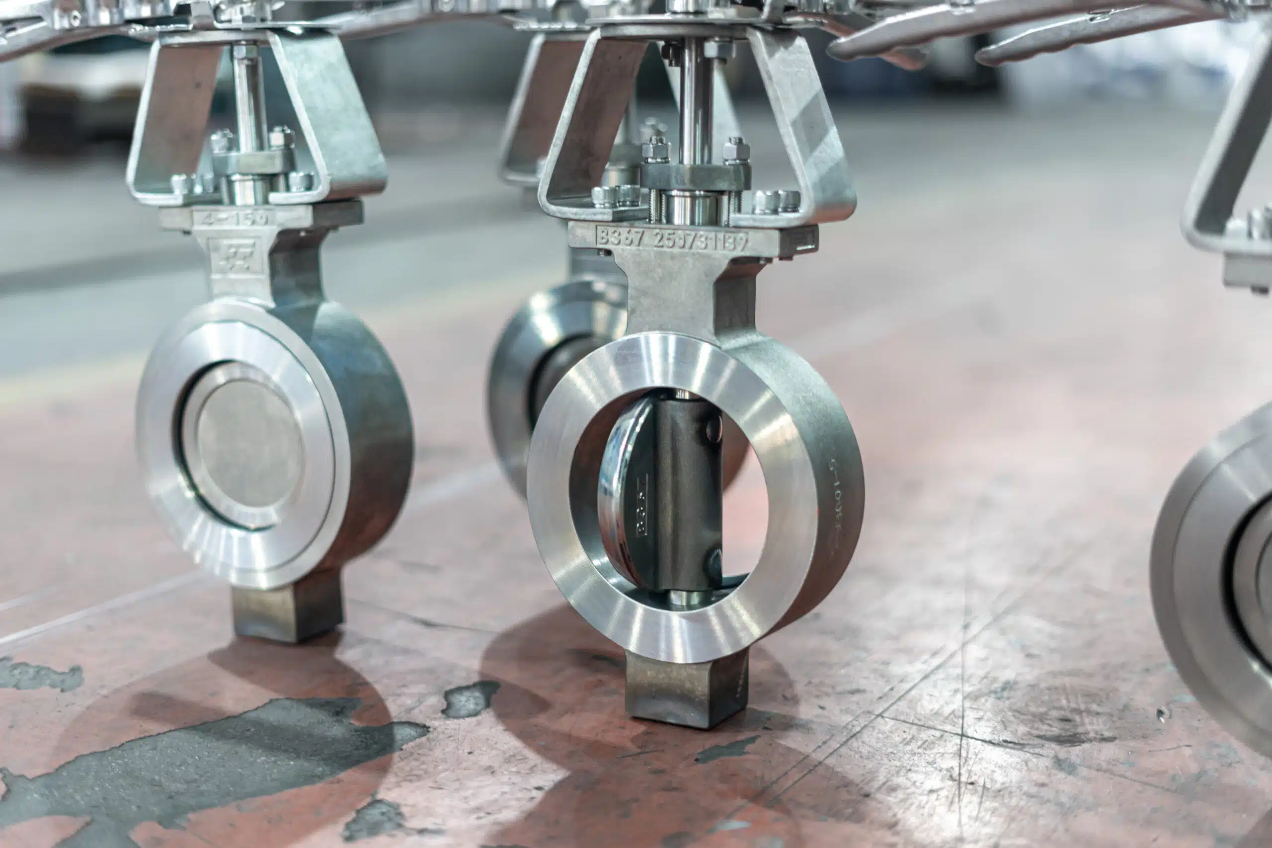
A wafer butterfly valve is a compact quarter-turn valve installed between two pipe flanges. The valve body does not have its own full flanges. Instead, it is centered between the pipeline flanges and held in place by long bolts or studs that pass through the flange bolt holes and clamp the valve body in position.
In buyer language, a wafer butterfly valve may also be called a wafer type butterfly valve, wafer style butterfly valve, or wafer body butterfly valve. These terms usually describe the same connection concept: a thin butterfly valve body installed between flanges rather than bolted with its own integral flanges.
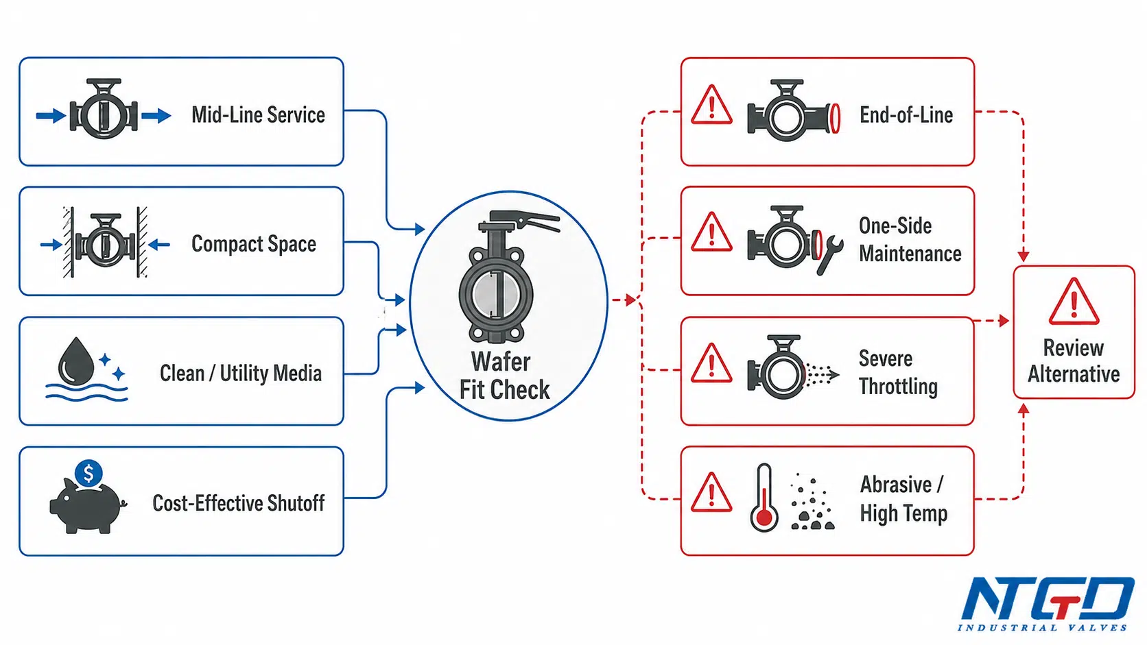
Wafer butterfly valves are commonly selected for water treatment, HVAC, utilities, and general industrial piping where compact installation, low weight, fast quarter-turn operation, and cost-effective shutoff are important. However, the wafer body style also has limits. It depends on proper flange alignment, even bolt tightening, correct seat selection, and support from both pipe flanges. For end-of-line service, one-side maintenance, severe throttling, abrasive media, high temperature, or high differential pressure, the design should be reviewed carefully before selection.
What Is a Wafer Butterfly Valve?
Quick Answer
A wafer butterfly valve is a butterfly valve with a slim body designed to fit between two pipe flanges. The disc rotates inside the flow path to open, throttle, or close the line. The valve is held in place by flange bolts or studs, and sealing depends on the valve seat or liner being compressed correctly between the flange faces.
| Question | Short Answer |
|---|---|
| What is it? | A wafer body butterfly valve installed between two pipe flanges. |
| Why is it called “wafer”? | The valve body is thin and compact compared with lug or flanged body styles. |
| How is it installed? | It is centered between pipe flanges and clamped by long bolts or studs. |
| What does it do? | It provides shutoff and, depending on design and service, limited throttling. |
| Best-fit use | Mid-line piping where compact installation, fast operation, and cost-effective shutoff are required. |
| Main boundary | It is usually not the first choice for end-of-line service or one-side maintenance unless the design and rating are confirmed. |
A wafer butterfly valve should not be treated as a generic butterfly valve without checking the connection style. The wafer body affects installation, sealing, maintenance access, and whether the valve can remain in service when one side of the pipeline is removed. In practical selection, it is usually a strong fit for compact mid-line service, but it normally needs support and compression from both pipe flanges.
Wafer Type, Wafer Style and Wafer Body Terminology
The terms wafer type butterfly valve, wafer style butterfly valve, and wafer body butterfly valve are often used interchangeably in RFQs and supplier discussions. In most cases, they all refer to a butterfly valve body that is mounted between two pipeline flanges.
The word wafer describes the body and connection style. It does not define the valve material, disc material, seat material, pressure class, operator type, or service suitability. A wafer valve may be manual, gear-operated, electric actuated, pneumatic actuated, plastic-bodied, stainless steel, ductile iron, soft-seated, or high-performance depending on the design.
In most RFQs, “wafer type” and “wafer style” point to the same connection concept. However, “style” is also used in comparison language such as wafer style vs. lug style, so the actual connection requirement should be checked instead of relying only on the name.
For RFQ clarity, it is better to specify “wafer butterfly valve” together with size, pressure class, flange standard, body material, disc material, seat material, and operation mode.
Wafer Butterfly Valve Connection Method
How the Wafer Body Fits Between Flanges
The most important feature of a wafer butterfly valve is the way it connects to the pipeline. The valve body is positioned between two pipe flanges. The valve itself normally does not have full integral flanges. Instead, the pipeline flanges provide the clamping force that holds the valve in place.
Some wafer bodies have alignment holes, guide holes, or body ears to help position the valve during installation. These features help with centering, but they should not be confused with lug-style threaded body lugs. A lug butterfly valve uses threaded lugs or separate bolt engagement to support a different installation and maintenance logic.
A wafer connection is compact, but it is also sensitive to installation quality. If the flanges are not parallel, if the valve is not centered, or if the bolts are tightened unevenly, the seat can be distorted and leakage or high operating torque may occur.
Through-Bolts, Flange Compression and Seat Sealing
In a typical wafer butterfly valve installation, long bolts or studs pass through the pipeline flanges and around the valve body. When tightened correctly, the flange faces compress the valve seat or liner area and help create the sealing interface.
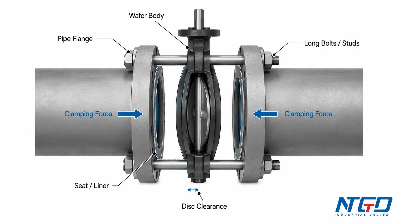
These bolts normally do not fasten into full integral valve flanges. Instead, they pass through the mating pipe flanges and around the wafer body to create the clamping force. This is a key visual and engineering difference from lug or flanged butterfly valve connections.
This is why the wafer connection should be evaluated as a system, not only as a valve body. The final sealing condition depends on:
| Connection Factor | Why It Matters |
|---|---|
| Flange standard | Confirms whether the valve body and bolt pattern fit the pipeline flanges. |
| Flange face condition | Damaged or dirty flange faces can cause external leakage. |
| Valve centering | Poor centering can create uneven compression or disc interference. |
| Seat / liner design | The seat often forms the sealing interface against the flange face. |
| Bolt tightening pattern | Uneven tightening can distort the seat or body. |
| Pipe internal diameter | Disc clearance must be checked to avoid contact during operation. |
For many resilient seated wafer butterfly valves, the seat or liner may function as the sealing interface. Extra gaskets should not be assumed. Gasket use must be checked against the valve design, flange face, manufacturer IOM, and project specification.
Why Flange Alignment Matters
Flange alignment has a direct effect on valve performance. If the flanges are offset, angled, or pulled into position by the bolts, the valve body may be stressed before the line is even pressurized. This can lead to seat deformation, uneven sealing, hard operation, or disc rubbing inside the pipe.
A wafer butterfly valve should not be used to correct pipe misalignment. The piping should be aligned and supported before the valve is installed. The valve should be centered between the flanges, and the disc should have enough clearance to rotate without contacting the pipe or gasket area.
In engineering review, flange misalignment is often linked to later troubleshooting symptoms. Uneven seat compression can show up as external leakage, high operating torque, incomplete closure, or disc edge damage after startup.
Main Components of a Wafer Butterfly Valve
A wafer butterfly valve has fewer major external body features than a flanged valve, but each component still affects selection and service reliability. For RFQ and technical review, the key point is not only naming the parts but understanding what each part changes in the application.
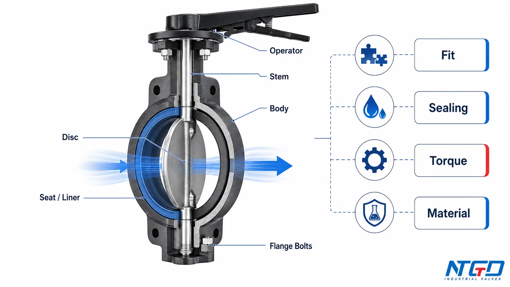
| Component | Function | What Buyers Should Check | Selection / Failure Impact |
|---|---|---|---|
| Body | Supports the wafer installation between flanges. | Body material, wafer profile, flange compatibility, face-to-face length. | Affects fit, weight, corrosion resistance, and installation stability. |
| Disc | Rotates inside the flow path to open, throttle, or close the valve. | Disc material, coating, edge condition, shaft connection. | Affects shutoff, wear resistance, corrosion resistance, and flow restriction. |
| Seat / liner | Provides the sealing interface between disc, body, and flange area. | EPDM, NBR, PTFE, metal seat, or other service-compatible material. | Affects leakage risk, chemical compatibility, temperature limits, and operating torque. |
| Stem / shaft | Transfers torque from the operator to the disc. | Stem material, stem-to-disc connection, corrosion resistance. | Affects operation reliability and actuator sizing. |
| Operator / actuator interface | Opens, closes, or modulates the valve. | Lever, gear, electric actuator, pneumatic actuator, or hydraulic actuator. | Affects automation, torque margin, operating speed, and control method. |
| Bolts / flange interface | Provides clamping force through the pipe flanges. | Bolt pattern, flange standard, alignment, tightening sequence. | Affects external sealing, body centering, and installation reliability. |
| Sealing interface: seat / liner vs. extra gasket | Defines whether sealing is handled by the valve seat / liner, an extra gasket, or a project-specific arrangement. | Seat design, flange face, IOM requirement, and gasket compatibility if used. | Wrong gasket use can cause over-compression, leakage, high torque, or disc interference. |
For a deeper breakdown of body, disc, stem, seat, seals and actuator functions, see NTGD’s butterfly valve parts and components guide.
Gasket and Seat Boundary Note
Treating the gasket as a standard component of every wafer butterfly valve can create installation errors. In many resilient seated wafer butterfly valves, the seat or liner extends to the flange face and performs the flange sealing function.
Adding extra gaskets without checking the valve design may over-compress the seat, increase operating torque, reduce disc clearance, or create leakage paths. The safer approach is to verify the seat / liner design, flange face condition, and manufacturer IOM before adding any gasket.
How Does a Wafer Butterfly Valve Work?
Open, Throttling and Closed Positions
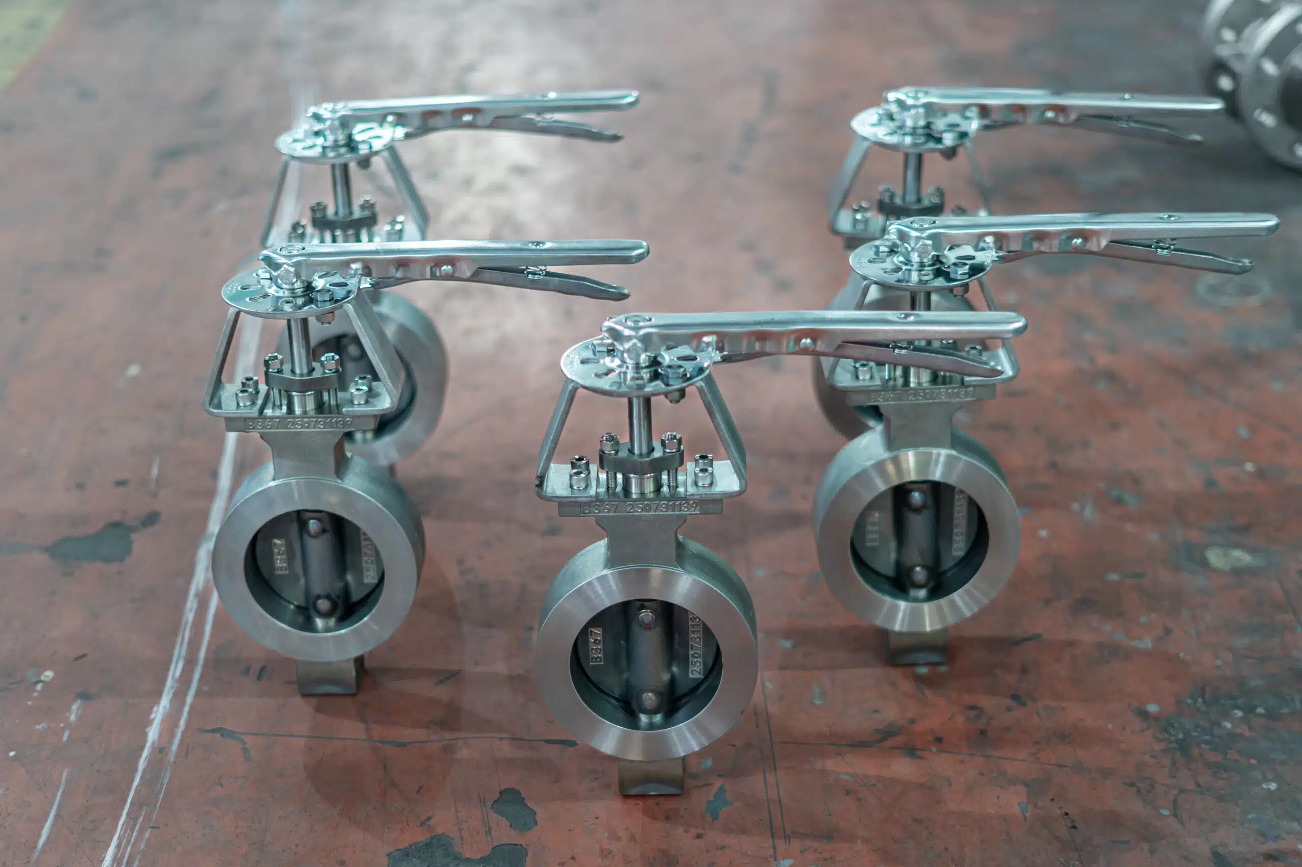
A wafer butterfly valve works by rotating a disc through a quarter turn. The disc is connected to a stem or shaft, and the stem is operated by a lever, gear, electric actuator, pneumatic actuator, or hydraulic actuator.
In the open position, the disc turns roughly in line with the flow path, allowing media to pass through the valve. In the closed position, the disc rotates across the flow path and presses against the seat or liner to shut off the line. Between fully open and fully closed, the disc can restrict flow and provide limited throttling, depending on the design and service conditions.
A wafer butterfly valve can be suitable for on-off service and some flow regulation duties, but it should not automatically be treated as a precision control valve. Throttling performance depends on disc design, seat material, actuator control, flow velocity, pressure differential, and whether the service creates vibration, cavitation, erosion, or seat wear.
Sealing Logic and Flow Path Considerations
The disc of a butterfly valve remains inside the flow path even when the valve is open. This creates a different flow profile from full-bore ball valves or gate valves. For most general shutoff applications, this is acceptable. For severe throttling, slurry, high velocity, or high-pressure differential service, the flow path and disc exposure should be reviewed more carefully.
Sealing depends on the relationship between the disc, seat, body, and flange compression. If the seat is damaged, chemically incompatible, swollen, over-compressed, or misaligned, the valve may leak internally or become hard to operate. If the disc contacts the pipe or flange area, the valve may fail to close fully or the disc edge may be damaged.
This working principle also explains why disc clearance, seat condition, and actuator torque directly affect shutoff reliability, operating effort, and troubleshooting results.
Types, Materials and Operation Options
Wafer butterfly valves can be classified by body and seat design, operation method, and material combination. The connection style is only one part of the specification.
By Body / Seat Design
| Design Route | Typical Role | Selection Boundary |
|---|---|---|
| Concentric / resilient seated wafer butterfly valve | Common choice for water, HVAC, and general utility shutoff. | Seat material must match medium and temperature. |
| Soft-seated wafer butterfly valve | Provides sealing with elastomer or polymer seat materials. | Not all soft seats are suitable for high temperature, chemicals, or abrasive media. |
| PTFE-lined or chemically resistant design | Used where corrosion resistance is important. | Liner, disc, stem, and body compatibility must be checked against medium concentration and temperature range. |
| High performance wafer butterfly valve | May be used for higher duty or more demanding applications. | Review pressure differential, required shutoff performance, temperature, seat design, actuator torque, and whether a high performance butterfly valve route is more suitable before selection. |
| Metal-seated or offset design | Used where soft seats are not suitable. | Requires careful review of leakage requirement, temperature, and pressure differential. |
This article does not replace a full butterfly valve types guide. The purpose here is to show which design routes may appear inside a wafer butterfly valve specification.
By Operation Method
| Operation Option | Typical Use | Selection Note |
|---|---|---|
| Manual lever wafer butterfly valve | Smaller sizes or simple manual operation. | Check handle clearance, locking position, and operator access. |
| Gear-operated butterfly valve | Larger sizes or higher operating torque. | Check gearbox torque, handwheel clearance, and operating frequency. |
| Electric actuated butterfly valve | Automated on-off or remote operation. | Check voltage, torque output, duty cycle, enclosure, and control signal. |
| Pneumatic butterfly valve | Fast actuation or plant automation. | Check air supply, actuator sizing, fail position, and accessories. |
| Hydraulic wafer butterfly valve | Special applications requiring high actuation force. | Usually reserved for high-force applications where pneumatic or electric actuation is not practical or sufficient. |
For actuator selection, the key issue is not only whether the valve is electric or pneumatic. The actuator must match valve torque, seat material, pressure differential, operating frequency, safety position, and control logic.
By Material and Service Condition
| Material / Seat Route | Where It May Fit | Boundary |
|---|---|---|
| Ductile iron or cast iron body | Water, HVAC, and general service. | Check coating, pressure rating, and water quality. |
| Carbon steel body | Industrial utility or general process service. | Check corrosion allowance and temperature range. |
| Stainless steel wafer butterfly valve | Corrosive, cleaner, or stainless piping systems. | For stainless construction routes, compare the broader stainless steel butterfly valve requirements with the wafer body and seat design. |
| Plastic wafer butterfly valve | Corrosive or lightweight piping systems. | Check pressure, temperature, flange compatibility, and mechanical strength. |
| EPDM seat | Water and some utility services. | Not suitable for every chemical or oil service. |
| NBR seat | Some oil or air services. | Check temperature and chemical compatibility. |
| PTFE seat / liner | Chemical resistance applications. | Check temperature, pressure, concentration, and mechanical loading. |
| Metal seat | Higher temperature or severe service review. | Check leakage requirement, operating torque, and pressure differential. |
Material selection should always be service-based. A material that works well in clean water may fail quickly in abrasive slurry, high-temperature steam, aggressive chemicals, or dry powder service.
For broader engineering context, material selection for valves should consider pressure, temperature, media corrosiveness and erosive properties, rather than body material alone.
Advantages, Application Fit and Best-Use Conditions
Engineering Advantages
Wafer butterfly valves are popular because they solve several practical piping problems with a compact body style.
| Advantage | Engineering Meaning | Boundary |
|---|---|---|
| Compact body | Shorter and lighter than many flanged valve bodies. | Still requires flange and operator clearance. |
| Lower weight | Easier to handle and install in many pipe sizes. | Piping support may still be required. |
| Cost-effective body style | Uses less body material than many lug or flanged designs. | Lowest initial body cost does not guarantee the lowest lifecycle cost if seat replacement, actuator oversizing, or installation rework becomes necessary from misapplication. |
| Fast quarter-turn operation | Opens and closes quickly. | Fast operation may not be suitable for every system condition. |
| Simple mid-line installation | Fits between two pipeline flanges. | Alignment and tightening quality are critical. |
| Multiple operation options | Can be manual, gear-operated, electric, pneumatic, or hydraulic. | Actuator sizing must match torque and service. |
| Broad material options | Can be configured for many clean or moderately demanding services. | Material and seat compatibility must be checked against medium, temperature, and operating duty. |
The main advantage of a wafer butterfly valve is not that it is “best” for every system. Its value is strongest where compact installation, simple shutoff, moderate cost, and quick operation fit the service conditions.
Typical Application Fit
| Application / Service | Fit Level | Notes |
|---|---|---|
| Water treatment | High | Common where seat and coating match the water quality. |
| HVAC / chilled water | High | Check temperature, insulation space, and actuator clearance. |
| General industrial utilities | Medium to high | Define pressure, temperature, medium, and operation frequency. |
| Air or low-pressure gas service | Conditional | Check sealing requirement, seat compatibility, and leakage tolerance. |
| Chemical service | Conditional | May require PTFE lining, stainless components, or other compatible materials depending on medium concentration and temperature. |
| Food or sanitary service | Conditional | Requires sanitary design, surface finish, and documentation if applicable. |
| Slurry or abrasive media | Caution | Disc, seat, solids content, velocity, and wear pattern must be reviewed. |
| High temperature service | Caution | May require metal-seated or high-performance design review rather than a standard soft seat. |
| Severe throttling | Caution | May require high-performance, control-focused, or alternative valve design review. |
Wafer butterfly valves are most straightforward in clean or moderately demanding services. As the medium becomes more corrosive, abrasive, hot, viscous, or unstable, the selection path moves from simple product choice to material, seat, velocity, and maintenance review.
Limitations and When to Review Alternatives
Wafer vs Lug vs Flanged Boundary
A wafer valve is often compared with lug and flanged butterfly valves. The comparison matters, but it should not take over the current page. The key boundary is how the valve is supported and maintained in the pipeline.
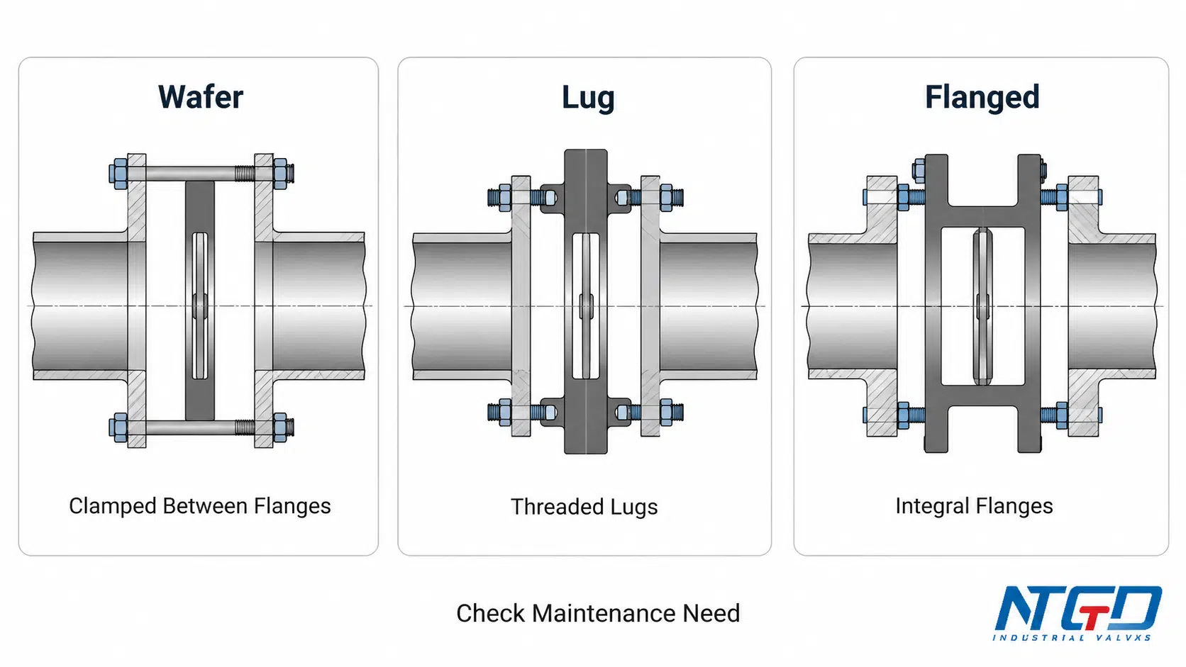
| Connection Type | How It Connects | Strength / Maintenance Boundary | Engineering Selection Note |
|---|---|---|---|
| Wafer butterfly valve | Clamped between two pipe flanges by long bolts or studs. | Usually depends on both flanges for support and sealing. | Strong fit for compact mid-line service when both flanges remain in place. |
| Lug butterfly valve | Uses body lugs, often with threaded bolt engagement. | May support one-side isolation or end-of-line service if designed and rated for it. | Review when one-side maintenance, section isolation, or dead-end duty is required. |
| Flanged butterfly valve | Has integral body flanges bolted directly to pipe flanges. | Heavier body and more direct piping connection. | Review when a more rigid flanged connection or project flange requirement is specified. |
For a deeper connection-specific comparison, use the dedicated Lug butterfly valveUses body lugs, often with threaded bolt engagement.May support one-side isolation or end-of-line service if designed and rated for it.Review when one-side maintenance, section isolation, or dead-end duty is required.Flanged butterfly valveHas integral body flanges bolted directly to pipe flanges.
<valve.com/comparison-wafer-type-butterfly-valve-vs-flanged-butterfly-valve/”>wafer-type vs flanged butterfly valve guide
rather than expanding the comparison inside this wafer valve article.
If the project requires one side of the piping to be removed while the valve remains installed, a wafer body may not be the right choice unless the valve design and rating specifically support that duty. Lug or flanged designs are often reviewed for those maintenance conditions.
Removing one flange while an unrated wafer valve remains under pressure or without verifying its support condition can lead to loss of flange support, loss of sealing, leakage, or media release.
End-of-Line, Maintenance and Severe Service Limits
A wafer butterfly valve is not automatically suitable for every installation. The following cases require additional review:
| Condition | Why It Needs Review |
|---|---|
| End-of-line service | A wafer valve usually needs support from both flanges unless specifically designed and rated otherwise. |
| One-side maintenance | Removing one side of the line may remove the clamping support needed for sealing. |
| Severe throttling | Disc exposure may increase vibration, noise, wear, or instability. |
| Abrasive slurry | Disc edge and seat wear can increase leakage and torque. |
| High temperature | Soft seat materials may not be suitable. |
| Aggressive chemicals | Body, disc, stem, and seat materials must all be compatible with the medium and temperature range. |
| High differential pressure | Seat load, actuator torque, and shutoff reliability must be checked. |
| Misaligned piping | The valve should not be used to pull flanges into position. |
The correct decision is not “wafer or not wafer” in isolation. It is whether the wafer body style matches the service, maintenance method, flange standard, seat material, actuator, and project specification.
Selection, RFQ and Installation Checks
Selection Checklist for Wafer Butterfly Valves
Before selecting a wafer butterfly valve, first check whether the service includes end-of-line duty, one-side maintenance, severe throttling, abrasive media, high temperature, or high differential pressure. If any of these conditions apply, the wafer body style should be reviewed before moving into routine material and actuator selection.
| Check Item | Why It Matters |
|---|---|
| Medium | Determines body, disc, stem, and seat material compatibility. |
| Pressure and temperature | Confirms whether the valve rating and seat material are suitable. |
| Pipe size / DN / NPS | Determines valve size, disc clearance, and actuator torque. |
| Flange standard | Confirms whether the wafer body fits the pipeline flanges. |
| Shutoff or throttling duty | Affects disc design, seat selection, and actuator control. |
| Seat / liner material | Affects leakage, temperature, chemical resistance, swelling risk, and operating torque. |
| End-of-line or maintenance requirement | May require review of lug or flanged alternatives. |
| Installation space | Confirms lever, gear, actuator, and handwheel clearance. |
| Operation mode | Manual, gear, electric, pneumatic, or hydraulic operation changes torque and control. |
| Test and certificate requirements | Affects inspection, documentation, and project acceptance. |
A clear selection checklist reduces the risk of ordering a valve that fits the flange but fails the service.
For broader body-style and RFQ decision logic, the butterfly valve selection guide can help compare wafer, lug, flanged and other butterfly valve routes before final specification.
RFQ Specification Checklist
For a wafer butterfly valve manufacturer or supplier to review the request accurately, the RFQ should include enough technical data. A short description such as “wafer butterfly valve, 6 inch” is usually not enough for engineering selection.
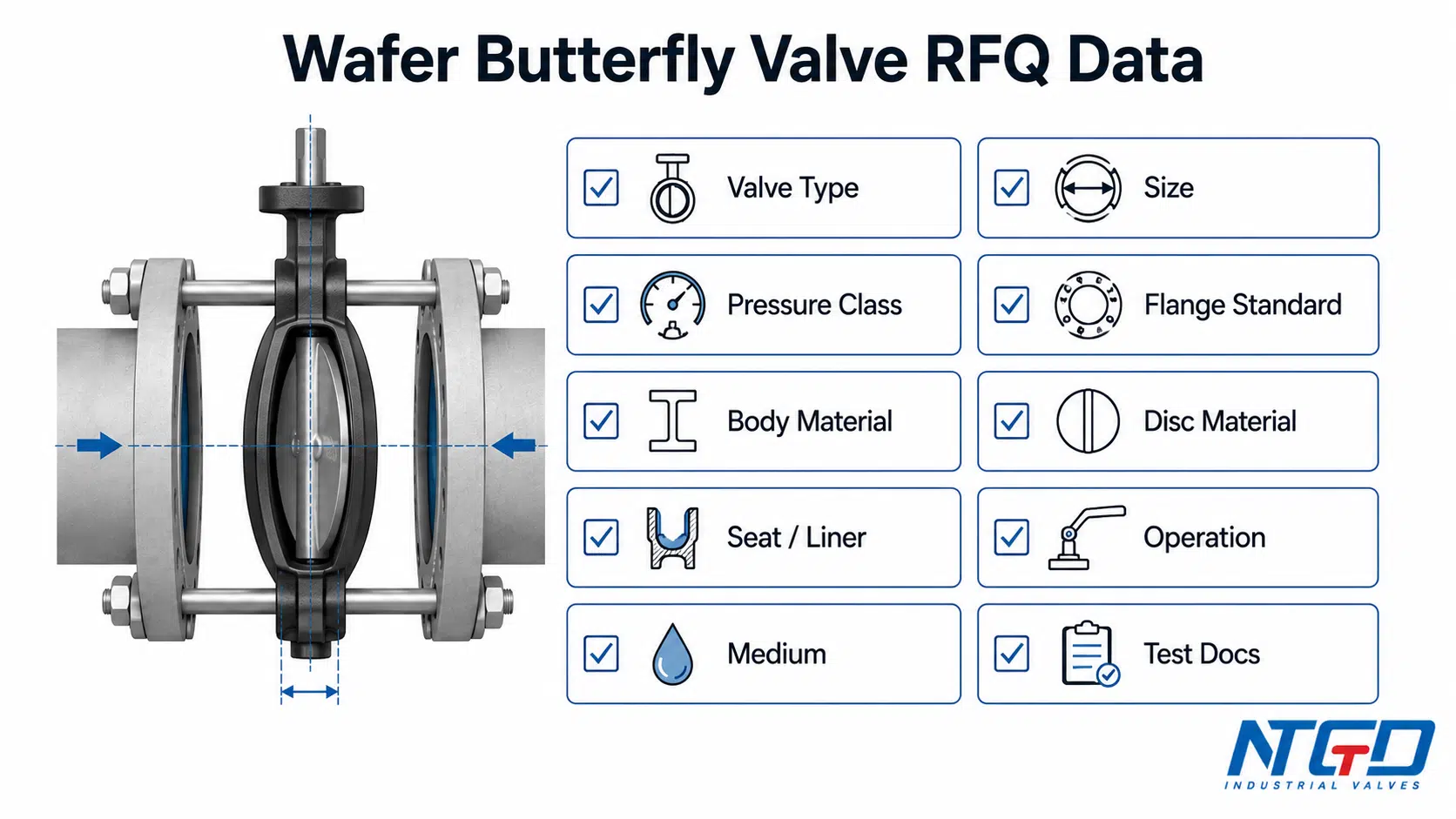
| RFQ Data | What to Provide |
|---|---|
| Valve type | Wafer butterfly valve or wafer type butterfly valve. |
| Size | DN / NPS and pipe schedule if relevant. |
| Pressure class | PN, Class, or project pressure rating. |
| Flange standard | Applicable flange standard or project flange requirement, such as ASME B16.5 when the project uses ASME pipe flanges. |
| Body material | Ductile iron, carbon steel, stainless steel, plastic, or other specified material. |
| Disc material | Stainless steel, coated disc, lined disc, or project-specified material. |
| Seat / liner material | EPDM, NBR, PTFE, metal seat, or other service-compatible material. |
| Stem material | Required stem material if specified. |
| Operation | Lever, gear, electric actuator, pneumatic actuator, or hydraulic actuator. |
| Medium | Water, air, chemical, slurry, powder, or other service. |
| Temperature | Normal and maximum operating temperature. |
| Quantity | Project quantity and spare requirement. |
| Test / inspection | Pressure test, inspection record, certificates, or document package. |
| Tag data | Line number, project tag, or datasheet reference. |
| Installation condition | End-of-line, buried service, outdoor service, actuator clearance, or special mounting notes. |
If the RFQ still lacks service-condition data, NTGD’s industrial valve selection guide can help organize medium, pressure, temperature, connection, material, sealing and actuation data before inquiry.
If dimensions are important, include the required face-to-face, flange standard, actuator envelope, and any drawing requirement in the RFQ. Do not assume that every wafer butterfly valve with the same size has the same dimensional envelope.
Installation Notes and Common Mistakes
This section is not a full installation procedure. The final installation should follow the manufacturer IOM, project specification, and applicable site requirements. The notes below highlight common checks that affect sealing and operation.
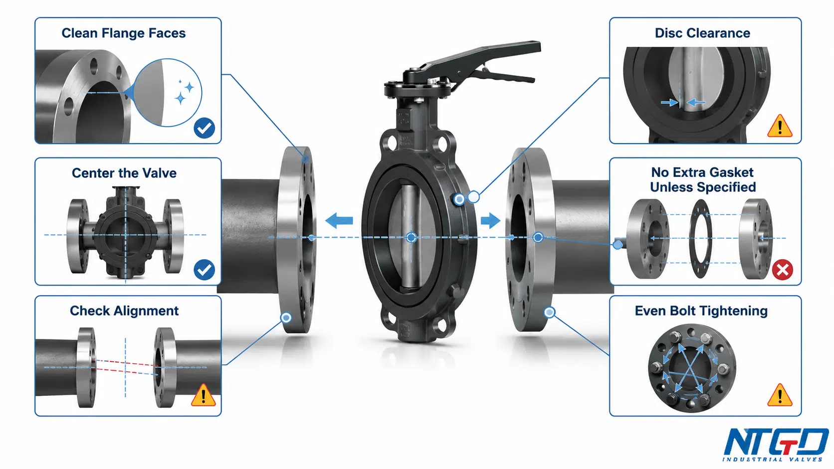
| Installation Point | Why It Matters | Avoid |
|---|---|---|
| Clean pipe and flange faces | Dirt, weld slag, or scale can damage the seat or cause leakage. | Installing against dirty flange faces and then treating leakage as a valve defect. |
| Confirm flange alignment | Misalignment can distort the seat and body. | Pulling the pipe into position with bolts, which may lead to uneven compression or hard operation. |
| Center the valve between flanges | Correct centering supports even compression and disc clearance. | Leaving the valve offset in the flange gap, which may cause disc rubbing. |
| Follow the IOM for disc position | Disc position during installation can affect seat protection and clearance. | Applying one universal disc angle to all designs. |
| Avoid extra gaskets unless specified | Many resilient seated designs use the seat / liner as the sealing interface. | Adding gaskets without checking the IOM, which may cause over-compression, high torque, or leakage. |
| Tighten bolts gradually and evenly | Even compression reduces seat distortion and leakage risk. | Fully tightening one side first, which may deform the seat or body. |
| Check disc clearance | The disc must rotate without contacting the pipe or flange area. | Forcing the valve open or closed when disc interference is present. |
| Cycle the valve after installation | Confirms smooth operation before startup. | Skipping operational checks and discovering torque or closure issues during commissioning. |
| Check for leakage after startup | Early leakage may indicate alignment, seat, or bolt compression issues. | Assuming all leakage is caused by valve quality alone. |
Many wafer butterfly valve problems start with installation conditions rather than valve design. Flange alignment, seat compression, and disc clearance should be checked before blaming the actuator or replacing the valve.
Troubleshooting and FAQ
Troubleshooting Matrix
For wafer butterfly valves, start troubleshooting with flange alignment, bolt compression, seat condition, and disc clearance before assuming the valve body or actuator is defective.
| Problem | Likely Cause | What to Check | Recommended Action |
|---|---|---|---|
| Valve does not close completely | Disc interference, seat damage, actuator travel stop, debris in the line. | Pipe ID, disc edge, seat condition, actuator limit setting. | Inspect clearance, clean the line, check seat and operator setting. |
| Hard operation or high torque | Over-compressed seat, flange misalignment, swollen seat, wrong actuator sizing. | Flange alignment, bolt compression, seat material, actuator output. | Recheck installation, review seat compatibility, resize actuator if needed. |
| External leakage | Uneven bolt tightening, damaged seat face, dirty flange surface, misalignment. | Flange faces, bolt pattern, liner edge, body centering. | Clean and realign, tighten evenly, inspect seat / liner condition. |
| Internal leakage | Worn seat, damaged disc edge, incompatible seat material, incomplete closure. | Disc edge, seat surface, actuator travel, medium compatibility. | Replace damaged sealing parts and review material selection. |
| Stem or packing leakage | Packing wear, stem corrosion, improper adjustment. | Stem area, packing condition, operating frequency. | Adjust or replace packing according to valve design. |
| Actuator mismatch | Insufficient torque, wrong fail position, incorrect control setup. | Valve torque data, actuator output, air supply or voltage. | Review actuator sizing and control requirements. |
| Seat swelling or degradation | Chemical or temperature incompatibility. | Medium, temperature, seat material, exposure time. | Select a compatible seat material. |
| Noise or vibration | Poor throttling condition, high velocity, unstable flow, wrong valve position. | Operating angle, flow condition, pressure differential, piping support. | Review service conditions and valve sizing. |
| Disc damage after installation | Pipe interference, forced operation, wrong gasket use. | Pipe bore, flange gap, gasket thickness, disc edge. | Stop operation and inspect clearance before reuse. |
Troubleshooting should start with the installation and service data. If the same problem repeats after replacing parts, the root cause may be flange alignment, seat selection, actuator sizing, or unsuitable service conditions.
Frequently Asked Questions
What is a wafer type butterfly valve?
A wafer type butterfly valve is a butterfly valve with a compact wafer body designed to fit between two pipe flanges. It is clamped by flange bolts or studs rather than bolted with its own integral flanges.
Is a wafer butterfly valve the same as a wafer style butterfly valve?
In most buyer and supplier discussions, yes. “Wafer butterfly valve,” “wafer type butterfly valve,” and “wafer style butterfly valve” usually refer to the same connection style. The exact design still depends on body material, seat material, disc design, pressure class, and operator type.
What is the difference between a wafer and lug butterfly valve?
A wafer butterfly valve is clamped between two flanges by shared bolts or studs that run through the mating flanges and around the valve body. A lug butterfly valve has body lugs or threaded inserts that allow each flange side to be bolted more independently.
This structural difference affects maintenance and end-of-line capability. Wafer designs are usually stronger for compact mid-line service, while lug designs are often reviewed when one-side isolation or end-of-line service is required.
Can a wafer butterfly valve be used for end-of-line service?
A wafer butterfly valve is usually not the default choice for end-of-line service because it often depends on support and compression from both pipe flanges. If one flange is removed and the valve is not rated for that condition, sealing support may be lost and leakage or media release may occur.
End-of-line use should be checked against the valve rating, manufacturer instructions, and project specification before selection.
Do wafer butterfly valves need gaskets?
Not always. Many resilient seated wafer butterfly valves use the seat or liner as the sealing interface against the flange faces. Extra gaskets can over-compress the seat or reduce disc clearance if the valve is not designed for them.
Gaskets should only be used if the valve design, flange condition, and manufacturer IOM require them.
Should a wafer butterfly valve be open or closed during installation?
The correct disc position depends on the manufacturer’s installation instructions and valve design. The disc should be positioned so that the seat and disc are protected while enough clearance remains for the disc to rotate without contacting the pipe or flange area.
Do not rely on one universal open-or-closed rule for every wafer butterfly valve.
What causes leakage after installing a wafer butterfly valve?
Common causes include dirty flange faces, flange misalignment, uneven bolt tightening, incorrect gasket use, seat damage, wrong seat material, or disc interference. Leakage should be checked against both valve condition and installation condition.
Can wafer butterfly valves be used for throttling?
Some wafer butterfly valves can be used for limited throttling, but not every wafer valve is suitable for severe throttling or control service. Limited throttling may be acceptable in moderate service, while severe throttling, high velocity, high differential pressure, vibration, or abrasive media may require a high-performance or control-focused design review.
How do I specify a wafer butterfly valve for RFQ?
Provide valve type, size, pressure class, flange standard, body material, disc material, seat or liner material, stem material, operation method, medium, temperature, quantity, test requirements, certificates, and tag data. Include installation or maintenance requirements if end-of-line service, actuator clearance, or special flange conditions matter.
Final Fit-Check Before Inquiry
Before sending an RFQ, confirm these items:
| Fit-Check Item | Confirmed? |
|---|---|
| Wafer body style is suitable for the piping layout. | |
| Both flanges support the intended installation condition. | |
| End-of-line or one-side maintenance requirements are known. | |
| Medium, pressure, and temperature are defined. | |
| Body, disc, stem, and seat materials are selected for the service. | |
| Flange standard and face-to-face requirements are confirmed. | |
| Manual, gear, electric, pneumatic, or hydraulic operation is specified. | |
| Installation space and actuator clearance are checked. | |
| Testing, inspection, and certificate requirements are listed. | |
| Tag data and project documents are ready. |
Conclusion
A wafer butterfly valve is a compact and practical choice when the piping system needs a lightweight quarter-turn valve installed between two flanges. Its value comes from simple mid-line installation, broad material options, and efficient shutoff in suitable services.
The same compact body style also creates important selection boundaries. Wafer valves depend on flange alignment, correct seat compression, suitable material selection, proper actuator sizing, and clear maintenance requirements. For end-of-line service, severe throttling, abrasive media, high temperature, aggressive chemicals, or one-side maintenance, the wafer design should be checked against the project specification and manufacturer data before approval.
Overall, a wafer butterfly valve is a cost-effective compact solution for suitable mid-line piping, but severe service and maintenance-sensitive installations require focused review of structure, material, seat design, and support conditions.
If the fit-check items above are not fully confirmed, or if the service falls into the caution zones described in this guide, provide the medium, size, pressure class, flange standard, body / disc / seat material, operation method, quantity, maintenance requirement, and testing requirements. NTGD Valve can review the wafer butterfly valve specification and help confirm whether a wafer, lug, or flanged butterfly valve design is more suitable for the service.
