
Author Name: Bruce Zheng
Author Role: Co-Founder and Valve Engineer at NTGD Valve
Author Bio: Bruce Zheng is Co-Founder and Valve Engineer at NTGD Valve, focusing on industrial valve selection, application, and technical content for global B2B buyers.
Last Updated: July 14, 2026
Quick Answer
Check valve cracking pressure is the minimum forward differential pressure at which the first detectable forward flow begins. It is the difference between upstream and downstream pressure—not the upstream pressure alone.
In most general technical discussions, check valve opening pressure refers to the same initial cracking threshold. In a formal datasheet, however, “opening pressure” may be defined at first movement, first detectable flow, a specified valve lift, or another flow condition. The definition and test criterion must therefore be confirmed before values from different valves are compared.
Reaching cracking pressure does not mean that the valve is fully open or able to pass the design flow. A valve operating only slightly above its cracking threshold may remain barely open, creating high flow resistance, unstable movement, chatter, or accelerated seat wear.
There is no universal best cracking pressure. The selected value must allow reliable opening at the minimum available system differential while also supporting stable minimum-flow operation, closure, resealing, and the required leakage performance.
What Is Check Valve Cracking Pressure?
Cracking Pressure as a Forward Differential Pressure
A check valve remains closed until the force generated by forward differential pressure becomes sufficient to overcome the forces holding the closure element on its seat.
The basic pressure relationship is:
ΔP = P(upstream) − P(downstream)
The valve begins to crack open when this differential generates enough opening force to overcome the relevant closing resistance.
For an external engineering definition, ScienceDirect describes cracking pressure as the upstream-to-downstream differential at which a check valve begins to open.
An upstream pressure value has little meaning without the concurrent downstream pressure. A high upstream pressure does not guarantee opening if nearly the same pressure exists downstream. This condition can occur in closed-loop systems, parallel pump discharge lines, or piping connected to an elevated or pressurized downstream vessel.
Conversely, a relatively low upstream pressure may be sufficient when the downstream pressure is much lower and the available differential exceeds the opening threshold.
Cracking pressure must therefore be treated as a differential-pressure parameter, not as a standalone inlet-pressure rating.
For the broader automatic opening and closing sequence, review how a check valve responds to pressure differential and reverse flow.
Is Opening Pressure the Same as Cracking Pressure?
In many check-valve specifications, opening pressure and cracking pressure describe the same general event: the point at which the closure element begins to move and forward flow becomes detectable.
They should not be assumed to be perfectly interchangeable in every datasheet. A manufacturer may define opening pressure as:
- the differential at the first visible or detectable flow;
- the differential at initial disc or poppet movement;
- the pressure required to reach a specified partial opening;
- or the differential associated with a more stable operating position.
Two published values should be directly compared only when they use the same:
- parameter definition;
- test medium;
- installation orientation;
- temperature;
- flow-detection criterion;
- and stated tolerance.
A result based on the first bubble in a low-flow test is not equivalent to a result based on sustained flow or a defined valve lift. Cross-brand or cross-model selection should not be based on the nominal number alone.
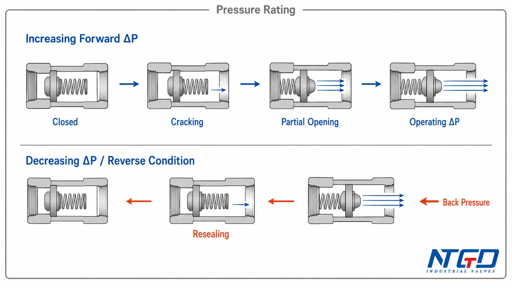
From Closed to First Crack, Partial Opening, and Stable Operation
A check valve does not normally move from fully closed to fully open as one binary event. Its behavior is better understood as a progression.
| Valve state | Closure-element condition | Flow condition | Relevant engineering question |
|---|---|---|---|
| Closed | Disc, ball, poppet, plate, or piston remains seated | No intended forward flow | What forces keep the valve closed? |
| Initial crack | Closure element begins to lift or rotate | First detectable forward flow | Has the cracking-pressure threshold been reached? |
| Partial opening | Opening increases as differential and flow rise | Limited or developing flow | Is operation stable, or is the valve near a chatter-prone condition? |
| Stable or more fully open operation | Closure element reaches a developed operating position | Normal operating flow | What is the operating pressure drop at the required flow rate? |
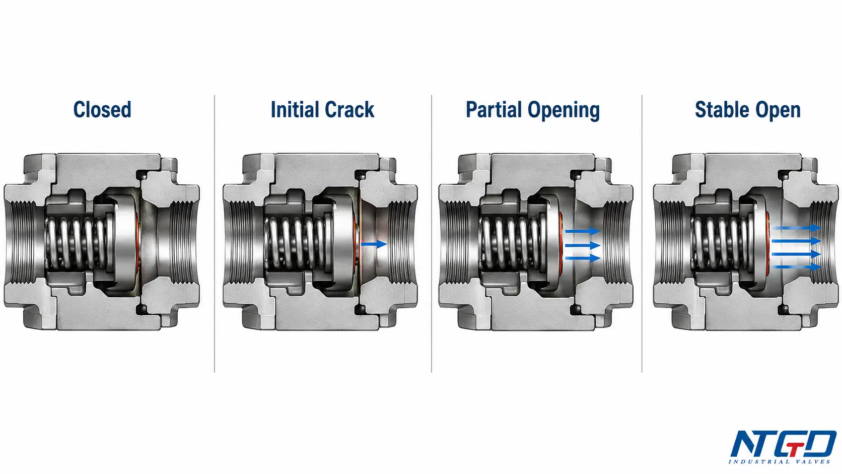
Cracking pressure confirms only the transition from closed to initial opening. It does not establish the flow rate at first crack, the differential required for substantial opening, the valve’s full capacity, or its normal-flow pressure drop.
Those later conditions depend on the valve’s opening curve, geometry, flow forces, spring behavior, and Cv or Kv performance. A specification that treats cracking-pressure compliance as proof of flow capacity can approve a valve that begins to open but cannot pass the required flow without excessive differential.
What Determines a Check Valve’s Cracking Pressure?
Spring Preload and Other Mechanical Closing Forces
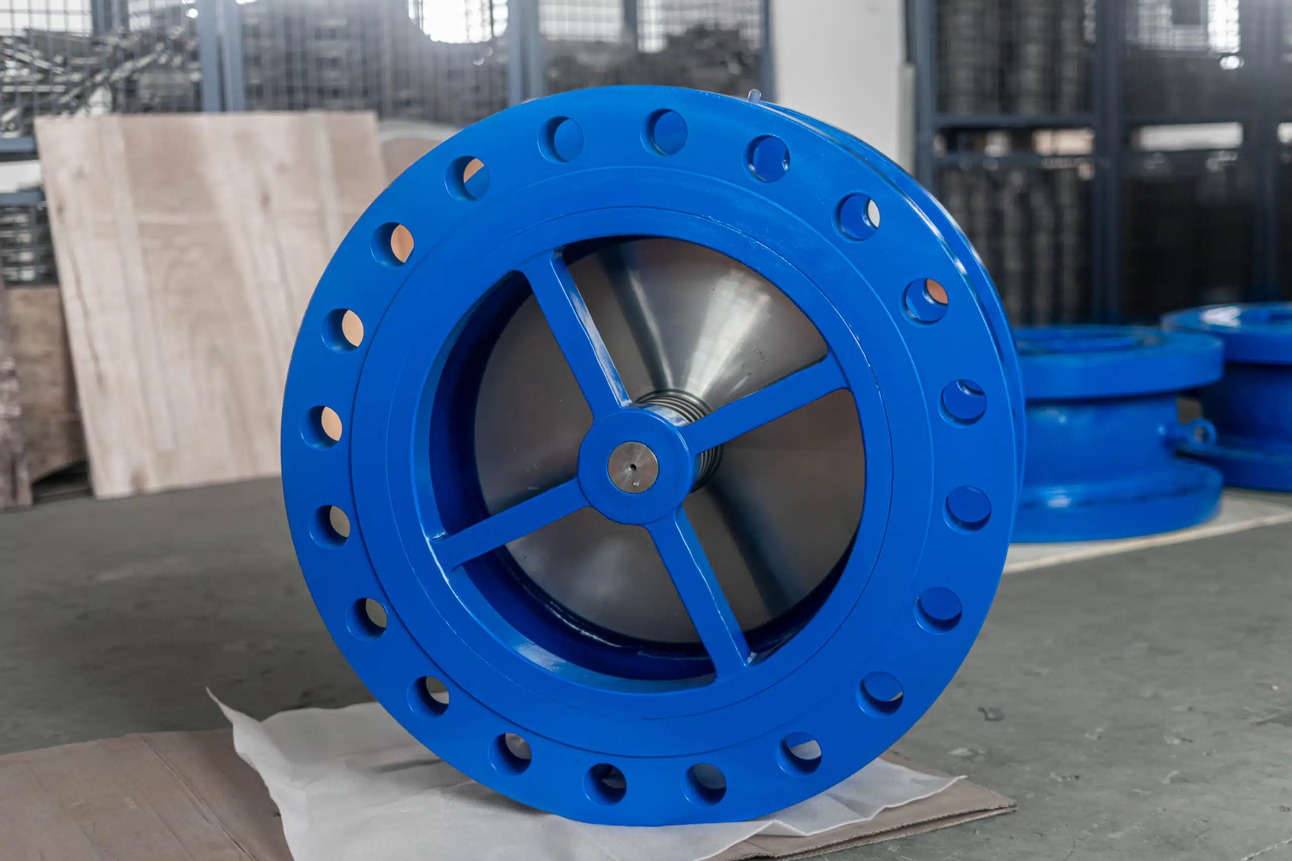
In a spring-assisted check valve, the spring is compressed while the valve is closed. This preload creates a closing force that the forward differential must overcome.
A stronger spring, greater initial compression, or an unfavorable mechanical arrangement generally increases the opening requirement. A lighter spring may reduce the initial threshold but may also reduce the force available for closure and resealing.
Spring preload is one possible source of closing resistance, not a universal feature of every check valve. Depending on the design, the opening force may also need to overcome:
- closure-element weight;
- gravity-induced moment;
- hinge or torsion-spring torque;
- guide friction;
- seat adhesion;
- seal compression;
- static friction after extended closure;
- and resistance caused by deposits or contamination.
A nominal spring setting should not automatically be treated as the complete installed cracking-pressure requirement.
The structure, installation boundaries, and application role of spring-loaded check valve designs are covered separately so that the present guide can remain focused on the cracking-pressure parameter.
Disc, Ball, Poppet, Plate, and Trim Weight
The mass, travel direction, and position of the moving element affect the opening threshold.
In a lift or piston check valve, the forward differential may need to lift a guided element away from the seat. When gravity opposes this movement, closure-element weight adds to the required opening force.
In a swing check valve, the fluid must create enough moment around the hinge to rotate the disc. The relevant resistance depends not only on total disc weight but also on:
- the center-of-gravity location;
- hinge position;
- disc angle;
- and effective moment arm.
In a ball check valve, ball weight, seat geometry, buoyancy, and orientation may all influence initial opening. In a dual-plate design, torsion springs, plate mass, shaft friction, and plate angle interact.
The same nominal valve size can therefore show materially different cracking behavior when its internal geometry or closing mechanism changes.
Gravity, Hinge Torque, Friction, and Seat Resistance
Gravity may assist opening, oppose opening, or act mainly during closure, depending on valve construction and installation direction.
Practical behavior also includes resistance that a simplified force balance may not capture, such as:
- guide friction in a piston or nozzle design;
- bearing or hinge friction in a swing valve;
- resilient-seat compression;
- adhesion after long periods in the closed position;
- and deposits that increase initial breakaway force.
A valve that has remained closed for an extended period may require a higher first-opening differential than a valve that has just completed an operating cycle. This effect becomes important when the application has only a small differential-pressure margin.
How Valve Design Changes the Opening Mechanism
Different check-valve mechanisms respond to pressure and flow in different ways.
| Valve mechanism | Main closing resistance | Opening behavior | Main calculation limitation |
|---|---|---|---|
| Spring-loaded poppet, piston, or axial closure | Spring preload plus moving-element weight, friction, and seat resistance | Mainly translating movement | A simplified force balance may be useful, but effective area, friction, and spring geometry must be confirmed |
| Swing check valve | Gravity-induced disc moment about the hinge, hinge friction, and any spring torque | Rotational movement around a hinge | A linear force-over-area calculation does not represent the full torque balance |
| Dual-plate check valve | Torsion-spring torque, plate inertia, shaft friction, and gravity effects | Two rotating plates | Plate angle and hydrodynamic moment change throughout travel |
| Lift or ball check valve | Moving-element weight plus guide, seat, buoyancy, and gravity effects | Vertical or guided movement | Installed orientation may materially change the net opening requirement |
| Nozzle or silent check valve | Spring preload, guided-disc mass, friction, seat resistance, and flow force | Axial translating movement | Static cracking pressure does not describe the complete dynamic opening curve |
The comparison shows why a single universal cracking-pressure formula cannot deliver the same accuracy across all check-valve designs.
How Wear, Contamination, and Seal Condition Can Shift Actual Behavior
Cracking pressure can change after installation because the actual closing mechanism no longer behaves as it did under the original test condition.
Potential causes include:
- spring fatigue or permanent set;
- corrosion or deposits on a guide;
- particulate contamination at the seat;
- increased bearing or hinge friction;
- seal swelling or hardening;
- seat damage;
- misalignment;
- and product buildup around the moving element.
Spring fatigue may reduce closing and resealing force. Fouling, guide wear, or hinge damage may increase the opening threshold or make it inconsistent. Seal aging or swelling may change both breakaway force and leakage behavior.
When a measured threshold shifts, first confirm that the test medium, orientation, temperature, and detection method have not changed. Then review the spring or closing mechanism, seat condition, guides or hinges, seal condition, contamination history, thermal cycling, and any extended period of inactivity.
The deviation should not be attributed to spring setting alone.
Nominal vs Net Cracking Pressure in an Installed Valve
Catalog Spring Setting vs Installed Opening Requirement
A nominal spring setting or published cracking-pressure value is usually based on defined reference conditions. These may include:
- a specified test medium;
- a particular installation orientation;
- a defined temperature;
- a controlled rate of pressure increase;
- and a stated method for detecting first flow.
The installed valve may experience forces that differ from those reference conditions.
For engineering review, it is useful to distinguish between:
- nominal cracking pressure: the stated or tested value under defined reference conditions;
- net installed opening requirement: the differential required after orientation, trim weight, fluid-column effects, friction, and service condition are considered.
“Net cracking pressure” is an engineering description rather than a universally standardized datasheet term. Project documentation should use the manufacturer’s defined terminology while still accounting for the installed force balance.
Horizontal, Vertical Flow-Up, and Vertical Flow-Down Installation
Orientation changes how gravity acts on the moving element.
In a horizontal line, the effect depends on the valve geometry and the direction of closure-element travel.
In vertical flow-up service, the fluid may need to lift the moving element against gravity. For some lift, ball, piston, or spring-assisted designs, this increases the net opening requirement.
In vertical flow-down service, gravity may assist opening but oppose reliable return to the seat. A low restoring force may allow easy initial opening while providing insufficient closure or resealing force as flow decays.
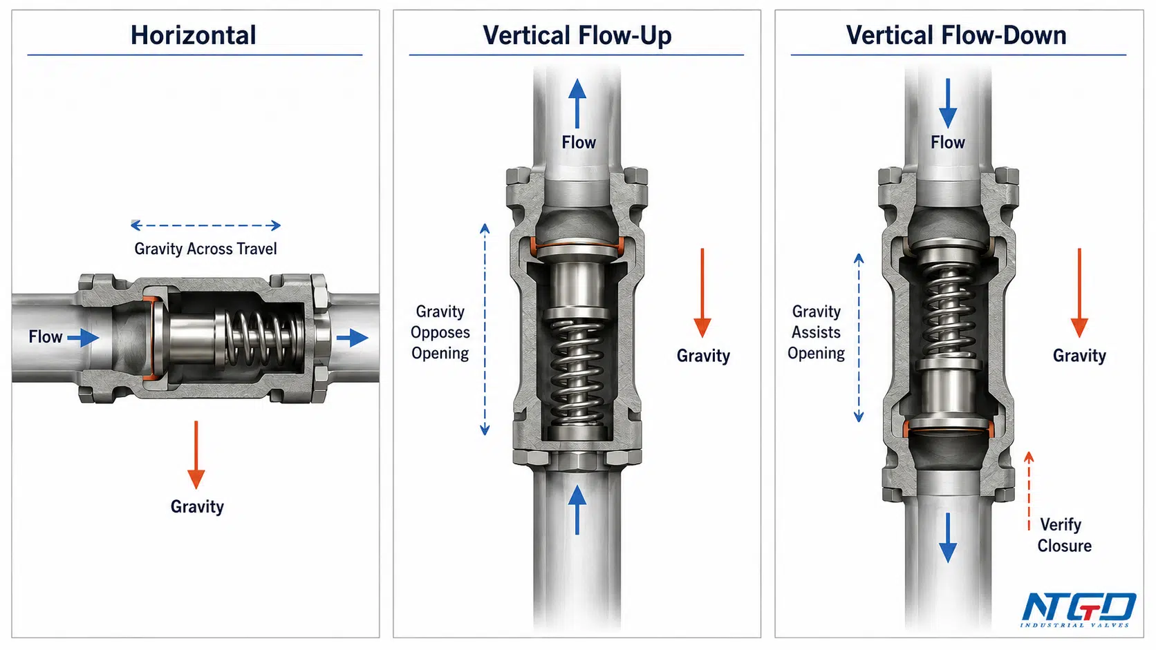
These relationships cannot be converted into one universal correction factor. The effect depends on:
- valve design;
- moving-element travel direction;
- center of gravity;
- spring arrangement;
- internal geometry;
- and any retained liquid column.
Trim Weight, Retained Fluid Column, and Gravity Direction
The installed force balance may include more than disc or poppet weight.
A retained fluid column can create static head that assists or opposes opening. This may matter in vertical piping, elevated systems, or arrangements where liquid remains trapped above or below the valve.
Trim weight and fluid-column effects must be evaluated in the same direction as the intended opening movement. A value demonstrated in horizontal testing may not represent the installed requirement in a vertical line.
| Factor | Possible effect on installed behavior | What should be confirmed |
|---|---|---|
| Closure-element or trim weight | May assist or oppose opening | Travel direction and center of gravity |
| Spring preload | Adds closing resistance | Nominal setting, tolerance, and orientation basis |
| Retained fluid column | May add static head in either direction | Piping arrangement and elevation |
| Guide or hinge friction | May raise or destabilize breakaway differential | Design, condition, and service cleanliness |
| Seat or seal resistance | May increase first-opening force | Seat material, compression, temperature, and condition |
| Gravity direction | Changes the net force balance | Horizontal, vertical flow-up, or vertical flow-down installation |
The final opening check should use the maximum permitted cracking pressure for the offered valve in the actual installation orientation, including the stated tolerance. A value tested in another orientation should not be substituted without documented confirmation that it remains applicable.
For broader flow-arrow, vertical-flow, pump-discharge, and spacing checks, use the check valve installation guide together with the offered valve’s IOM and datasheet.
If the supplier’s published data do not cover the project orientation, the datasheet review should request an orientation-specific confirmation or test basis.
Why Test Medium, Temperature, and Acceptance Criterion Matter
A cracking-pressure value is meaningful only when its test basis is clear.
The test medium may influence:
- buoyancy;
- viscous drag;
- seal wetting;
- leakage visibility;
- and the sensitivity of the detection method.
Temperature may affect spring behavior, elastomer properties, viscosity, and seat friction. These effects are material- and design-specific and should not be converted into a universal correction percentage.
The acceptance criterion is equally important. “Valve opens” may mean:
- the first bubble appears;
- the first measurable flow is recorded;
- the closure element visibly moves;
- or a defined minimum flow is achieved.
Two otherwise similar valves may show different published values because their detection criteria differ. Their numbers should not be treated as directly equivalent until the complete test basis is aligned.
How Is Check Valve Cracking Pressure Estimated?
The Simplified Closing-Force and Effective-Area Relationship
For a simplified translating closure, a preliminary estimate may begin with:
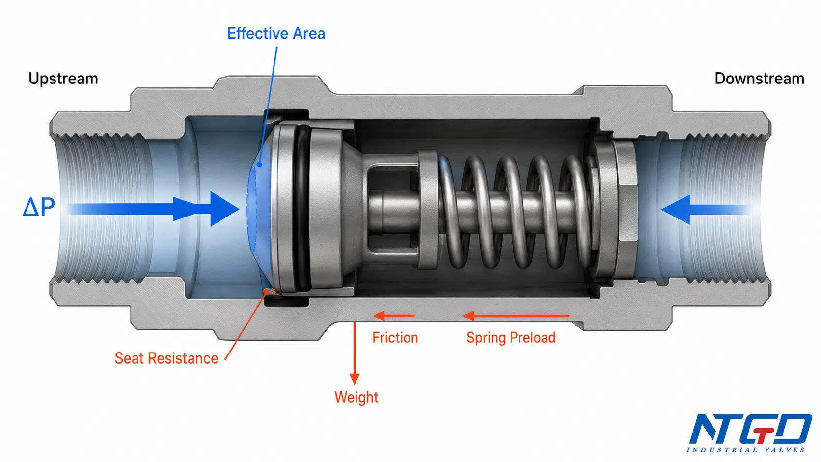
ΔP(crack, est.) ≈ F(closing) / A(effective)
The conceptual rearrangement follows the basic relation that pressure is force per unit area; the valve-specific challenge is identifying the actual closing resistance and effective pressure area.
where:
- ΔP(crack, est.) is the estimated forward differential pressure;
- F(closing) is the total closing resistance included in the model;
- A(effective) is the projected pressure area that produces opening force.
The closing-force term may be expressed conceptually as:
F(closing) = F(spring) + F(weight) + F(friction) + F(seat) + F(other)
The sign and direction of each term depend on the installation. A weight term that opposes opening in one orientation may assist it in another.
This is a conceptual force balance, not a certified universal calculation.
A Controlled Spring-Loaded Calculation Example
For a simplified spring-loaded translating closure:
F(spring) = k × x
where:
- k is the spring rate;
- x is the initial spring compression.
Consider a hypothetical example used only to demonstrate the calculation method:
- spring rate: 20,000 N/m;
- initial compression: 0.005 m;
- other estimated closing resistance: 20 N;
- effective pressure area: 0.003 m².
The spring preload is:
F(spring) = 20,000 × 0.005 = 100 N
The simplified total closing force is:
F(closing) = 100 + 20 = 120 N
The estimated cracking differential is:
ΔP(crack, est.) = 120 / 0.003 = 40,000 Pa
This equals approximately 40 kPa, or 0.40 bar.
Engineering limitation: This example applies only to a simplified translating spring-loaded mechanism with an assumed effective area and closing-force model. It must not be applied directly to swing, dual-plate, or other rotational designs, to valves with unknown effective area or friction, or as the final basis for project approval.
Manufacturing tolerance, actual seat friction, installation orientation, spring variation, and the test criterion may cause the installed opening requirement to differ measurably from this single-point estimate.
The offered valve should be verified using its drawing, spring data, orientation basis, test definition, tolerance, and actual rated or tested value.
Why Effective Area Is Not Automatically the Nominal Bore Area
A common calculation error is to use the nominal pipe bore area without checking the actual pressure-loaded geometry.
The opening force may act over:
- the seat projection;
- a poppet face;
- an annular area;
- a piston area;
- a differential area between pressure surfaces;
- or another geometry defined by the internal design.
The effective area may also change as the closure element begins to move.
Using nominal pipeline diameter can therefore overestimate or underestimate the true opening force. The area should be taken from the valve design, sectional drawing, calculation note, or supplier-confirmed geometry.
Why Swing, Dual-Plate, and Other Designs Need Different Models
A swing check valve is governed primarily by a torque balance around its hinge.
A design-specific rotational model may need to consider:
- fluid-force moment;
- disc-weight moment;
- hinge friction;
- spring torque, if fitted;
- disc angle;
- and the location of the pressure resultant.
A dual-plate design similarly involves torsion-spring torque, plate angle, shaft friction, gravity, and changing hydrodynamic moments.
These designs cannot be represented accurately by one fixed linear force divided by one fixed area. A conceptual comparison may help explain the physics, but final values require manufacturer testing or an appropriate design-specific model.
When to Stop Estimating and Use Manufacturer-Tested Data
A preliminary estimate can help identify:
- which forces control opening;
- which application inputs are missing;
- whether the available differential and expected threshold are of a similar scale;
- and whether a proposed value appears physically plausible.
Stop relying on the simplified estimate when:
- the internal geometry is unknown;
- the effective area cannot be confirmed;
- a rotational or torsion-spring mechanism dominates;
- the available differential is close to the expected threshold;
- the project requires a tightly controlled maximum value;
- the installed orientation differs from the test basis;
- the medium is highly viscous, dirty, or temperature-sensitive;
- resealing or leakage is critical;
- or transient behavior materially affects selection.
When the model boundary is unclear, the pressure margin is small, or cracking pressure is a project acceptance parameter, use test data for the offered configuration rather than extending the hand calculation.
Cracking Pressure vs Opening, Resealing, Back Pressure, and Operating Pressure Drop
The related terms describe different stages or duties of valve behavior. Treating them as interchangeable can produce an incorrect specification.
| Parameter | What it describes | When it applies | What should confirm it | Common mistake |
|---|---|---|---|---|
| Cracking pressure | Minimum forward differential at first detectable flow | Initial opening | Test medium, orientation, criterion, and tolerance | Assuming first crack proves full opening or flow capacity |
| Opening pressure | Often the same initial threshold, but the definition may vary | Initial movement, first flow, or another stated opening condition | Exact datasheet definition and test basis | Comparing values based on different lift or flow criteria |
| Full-open differential | Differential associated with a more developed opening position | Higher flow or greater valve travel | Opening curve or test data | Applying a universal multiplier to cracking pressure |
| Resealing pressure | Differential at which detectable forward flow stops and the valve returns toward closure | Decreasing forward differential | Test method and leakage criterion | Assuming it equals cracking pressure despite friction and hysteresis |
| Back pressure | Downstream pressure opposing forward flow or acting in reverse | Opening calculation, closure, and reverse-pressure service | System pressure profile and seat design | Counting downstream pressure twice after it is already included in ΔP |
| Operating pressure drop | Differential across the valve at a stated forward flow | Normal flowing operation | Cv, Kv, flow curve, or test data | Assuming it has a fixed relationship to the near-zero-flow cracking threshold |
| Pressure rating | Allowable pressure boundary of pressure-containing parts | Mechanical integrity | Applicable standard and datasheet | Confusing pressure class with opening threshold |
Initial Crack vs Full-Open Differential
At initial crack, the opening may be extremely small. Forward flow may be detectable while the flow path remains highly restricted.
As differential and flow increase, the valve moves toward a more developed operating position. The pressure required for that position depends on the opening curve, spring characteristic, geometry, and hydrodynamic forces.
There is no universal ratio between cracking pressure and full-open differential. Capacity approval requires valve-specific opening or flow-performance data.
Cracking Pressure vs Resealing Pressure
Cracking pressure describes the opening event as forward differential rises.
Resealing pressure describes the condition during decreasing differential when forward flow stops and the valve returns toward a closed or sealed state.
The two values may differ because of:
- spring behavior;
- friction;
- hysteresis;
- closure-element momentum;
- seat contact;
- and the test method.
A valve may crack open at one differential and reseal at another. The relationship should be confirmed against the required closure and leakage duty rather than assumed from the opening value.
Cracking Pressure vs Back Pressure
Back pressure is the pressure acting on the downstream side of the valve.
During forward operation, it is already included in:
ΔP = P(upstream) − P(downstream)
It should not be added again as a separate fixed resistance when cracking pressure is already stated as a differential.
Some older or project-specific specifications separately state the maximum downstream pressure against which the valve must still open. That is a system operating requirement used to establish the available differential; it is not an additional cracking-pressure term to be counted twice.
During reverse-flow conditions, downstream pressure can force the closure element toward its seat and affect sealing. Back pressure is therefore important to closure and resealing, but it is not the same parameter as cracking pressure.
Cracking Pressure vs Operating Pressure Drop and Cv
Cracking pressure is an initial opening threshold at zero or very low flow.
Operating pressure drop is the differential across the valve while it passes a specified forward flow. It is normally evaluated using:
- Cv or Kv;
- a manufacturer pressure-drop curve;
- tested flow coefficients;
- or an application-specific hydraulic calculation.
The relationship is not generally represented by:
ΔP(operating) = ΔP(cracking) + ΔP(Cv)
Spring force, valve travel, geometry, and hydrodynamic forces may all change after first crack.
The two required checks are therefore separate:
- Opening check: Will the valve begin to open under the minimum available differential?
- Flow-performance check: How much differential will it consume at the specified operating flow?
For Cv, Kv, head-loss, and normal-flow calculations, continue with the check valve pressure drop and Cv guide.
Confusing these checks can approve a valve that opens at startup but produces unacceptable operating pressure loss—or a valve with favorable Cv that cannot open under the worst startup condition.
Cracking Pressure vs Valve Pressure Rating
Pressure rating defines the pressure-containing capability of the valve body, cover, ends, and other pressure-boundary parts under specified conditions.
It does not define the differential required to open the valve.
A high-pressure-class valve can have a low cracking pressure, while a lower-pressure-class valve can have a higher opening threshold. Pressure class and cracking pressure must be specified and reviewed independently.
For the pressure-boundary review, ASME B16.34 covers valve pressure-temperature ratings, materials, testing, and marking; the cracking-pressure requirement must still be specified separately for the offered check-valve design.
What Happens When Cracking Pressure Is Too High or Too Low?
Risks of Excessive Cracking Pressure
If the available forward differential does not reliably exceed the valve’s maximum opening requirement, the valve may:
- remain closed during startup;
- open intermittently;
- operate at very small lift;
- restrict required flow;
- create excessive startup resistance;
- become unstable near the threshold;
- chatter or repeatedly contact the seat;
- experience accelerated wear;
- or prevent the system from reaching the intended capacity.
The risk is particularly relevant when:
- pump startup differential is limited;
- minimum flow is low;
- upstream and downstream pressures are nearly balanced;
- or the offered valve has a relatively strong closing mechanism.
Pressure-containing capability alone does not prove suitability. The valve must also pass the worst-case opening check.
Risks of an Overly Low Cracking Pressure
A lower threshold may help in systems with limited differential, but reducing closing resistance can create other problems.
Possible consequences include:
- slower or less decisive closure;
- reduced resealing force;
- increased reverse-leakage risk;
- greater orientation sensitivity;
- instability at very low flow;
- repeated movement around the seat;
- or insufficient restoring force in an unfavorable installation direction.
The result depends on the mechanism. A gravity-loaded swing valve, spring-loaded nozzle valve, and guided lift check do not respond in the same way.
Why Lower Cracking Pressure Is Not Automatically Better
The selected value must balance reliable opening with stable closure and sealing.
| Condition | Possible benefit | Possible risk | What should be verified |
|---|---|---|---|
| Higher cracking pressure | May provide stronger closing bias in some spring-assisted designs | Delayed opening, restricted startup flow, chatter, or insufficient capacity | Minimum available differential, startup condition, and minimum flow |
| Lower cracking pressure | Easier initial opening when available differential is limited | Weaker closure, reverse leakage, orientation sensitivity, or threshold instability | Resealing, leakage requirement, installation direction, and closing mechanism |
| Very small pressure margin | Efficient use of the available pressure budget | Normal variation in pressure, friction, temperature, or fouling may cause opening failure | Maximum cracking value including tolerance and worst-case system condition |
| Large available-pressure margin | Improves confidence that initial opening can occur | Does not by itself prove minimum-flow stability or acceptable operating pressure drop | Opening curve, minimum stable flow, and full flow-performance data |
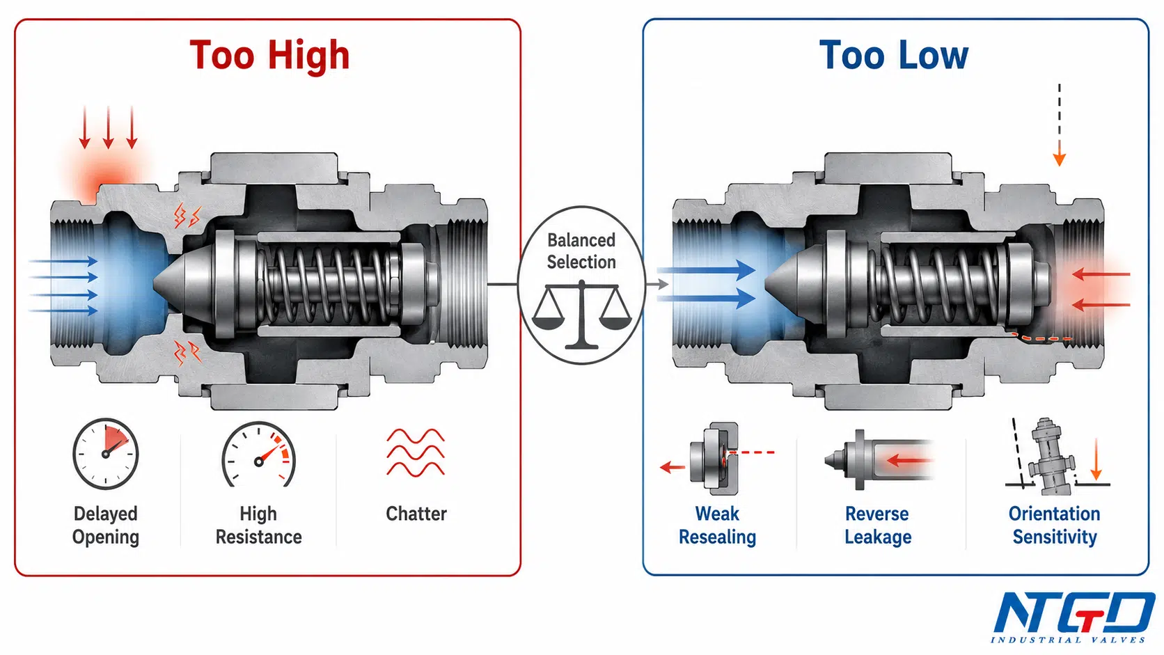
A suitable offered range must pass three checks:
- The valve opens at the minimum available forward differential.
- It remains stable at the required minimum flow.
- It closes, reseals, and meets the leakage requirement as flow decays or reverses.
The engineering objective is not the lowest available number. It is a cracking-pressure range that satisfies all three conditions for the offered valve and actual installation.
Signs That the Specified Value Does Not Match the Application
Possible indicators include:
- delayed downstream pressure buildup;
- flow beginning only after an unexpected pressure rise;
- intermittent flow during startup;
- audible or measurable chatter;
- repeated opening and closing at minimum flow;
- higher-than-expected valve differential;
- reverse leakage after flow stops;
- or different behavior after a change in installation orientation.
These symptoms do not prove that cracking pressure is the only cause. Valve sizing, pressure-drop performance, flow pulsation, contamination, seat condition, installation, and system transients should also be reviewed.
How to Select the Right Cracking Pressure for a Check Valve
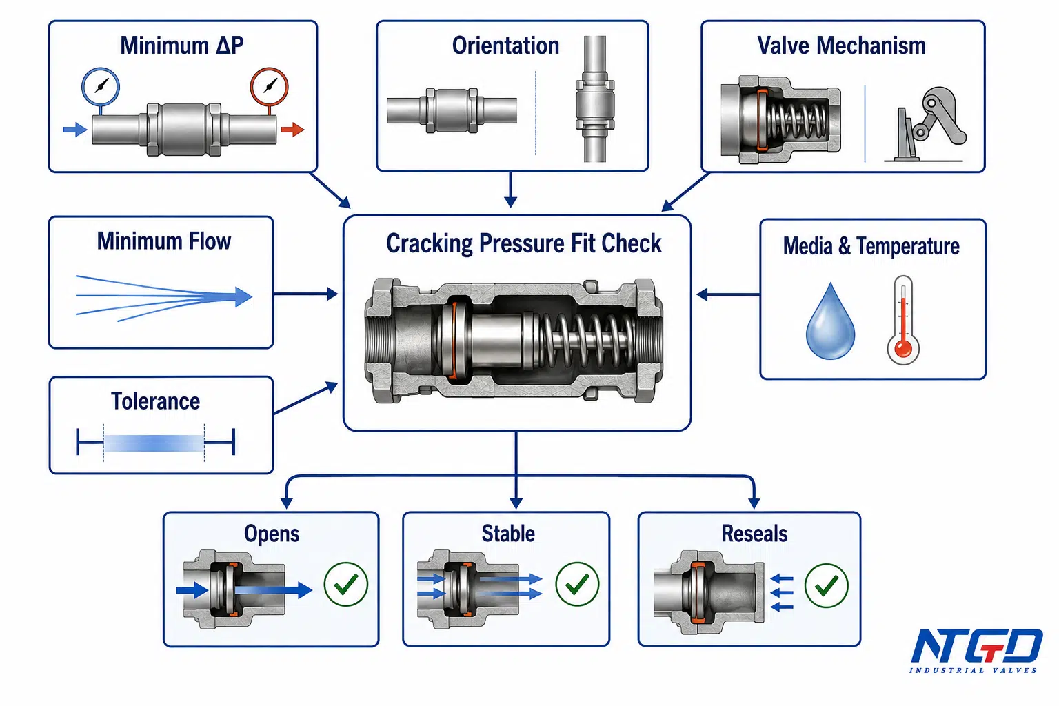
A practical review sequence is:
- Establish the minimum available forward differential.
- Confirm the actual installation orientation and closing mechanism.
- Review startup, minimum-flow, and normal-flow conditions.
- Check media, temperature, viscosity, solids, and fouling effects where relevant.
- Confirm resealing, reverse leakage, and shutoff requirements.
- Compare the system minimum differential with the offered valve’s maximum cracking pressure, then review operating pressure drop separately.
Cracking pressure is one part of the wider check valve selection process, which also reviews valve type, flow direction, pressure drop, installation, closing response, and RFQ data.
This is a review sequence rather than a universal priority formula. Project risk, data quality, and failure consequences may require some checks to be performed in parallel.
Start with the Minimum Available Forward Differential
Selection should begin with the lowest differential the system can reliably provide when the valve must open.
The review should consider:
- the lowest credible upstream pressure;
- the highest concurrent downstream pressure;
- startup conditions;
- minimum-flow operation;
- elevation and static-head effects;
- and normal process variability.
The maximum permitted cracking pressure of the offered valve—including tolerance and installed effects—must remain below the available differential after the project-required engineering allowance is applied.
That allowance should be based on system variability, instrument uncertainty, manufacturing tolerance, consequence of failure to open, and the project specification. It should not be replaced by a universal percentage.
Review Startup, Minimum-Flow, and Normal-Flow Conditions
A valve may perform acceptably at normal flow and still fail to open reliably during startup or low-flow operation.
Review at least three conditions:
- Startup: Is sufficient differential available before meaningful flow is established?
- Minimum flow: Will the closure element remain open and stable at the lowest required flow?
- Normal or maximum flow: Is operating pressure drop acceptable, and does the valve reach an appropriate operating position?
Cracking pressure primarily affects the first two conditions. Cv, Kv, and flow-curve data become increasingly important as flow rises.
Account for Media, Temperature, Density, and Viscosity Where Relevant
Media properties may affect installed behavior through:
- closure-element buoyancy;
- static liquid-head effects;
- viscous drag at small openings;
- seal compatibility and swelling;
- deposit formation;
- and the sensitivity of the detection method.
Density is relevant when closure-element weight or liquid-column head contributes to the force balance. Viscosity can influence low-flow behavior and the differential needed to produce a measurable indication.
These effects are design-specific. When the available pressure margin is small, they should be evaluated using applicable valve data or service-representative testing.
Match Valve Mechanism and Installation Orientation
The selection must match the pressure requirement and the physical closing mechanism.
A spring-loaded axial valve may provide controlled closure but require enough differential to overcome spring preload and other resistance.
A swing valve may show a low static opening threshold in a favorable orientation, while its minimum-flow stability, dynamic response, and reverse-flow behavior remain the controlling concerns.
A lift or piston valve may be strongly affected by travel direction and moving-element weight.
A dual-plate valve requires review of torsion-spring torque, plate movement, and flow stability.
Selection should therefore be based on the complete operating condition—not on the smallest published cracking-pressure number.
Check Resealing, Leakage, and Shutoff Expectations
The application may require:
- prevention of reverse flow;
- rapid closure;
- stable closure after pump trip;
- a defined leakage limit;
- or bubble-tight performance under stated conditions.
A low cracking pressure does not automatically provide the required resealing or leakage performance.
Clarify:
- the reverse pressure available during closure;
- whether the valve must seal with little downstream pressure;
- metal or resilient seat construction;
- the applicable leakage criterion;
- and whether closure speed is critical.
These requirements may influence spring setting, seat design, closure-element mass, and the acceptable cracking-pressure range.
Separate Opening-Threshold Review from Operating-Pressure-Drop Review
The offered valve must pass two independent checks:
- Opening check: Can the system exceed the valve’s maximum cracking pressure under the worst startup and minimum-flow condition?
- Flow-performance check: Is the operating pressure drop acceptable at the required flow?
Do not approve the valve based on only one check.
A low cracking pressure does not guarantee low operating pressure drop. A high Cv does not guarantee opening under the minimum startup differential.
Selection Inputs and Why They Matter
| Selection input | Why it matters | Risk if omitted | Preferred source |
|---|---|---|---|
| Minimum upstream pressure | Establishes the lowest driving pressure | The offered valve may fail to open during the weakest supply condition | Process design basis |
| Maximum concurrent downstream pressure | Determines the minimum available forward differential | The opening differential may be overstated | System pressure profile |
| Startup condition | Defines the pressure available before flow develops | Initial flow may be delayed or prevented | Pump or process startup analysis |
| Minimum and normal flow | Establishes stability and flow-performance requirements | The valve may chatter or create unacceptable pressure loss | Process flow data |
| Media and temperature | Affect seals, viscosity, buoyancy, and deposit formation | Reference test data may not represent the service condition | Fluid datasheet |
| Installation orientation | Changes gravity and the net force balance | The installed opening requirement may exceed the nominal value | Piping layout or GA |
| Valve mechanism | Determines whether force, torque, spring, weight, or flow effects dominate | An unsuitable calculation model or valve design may be selected | Valve design data |
| Resealing and leakage expectation | Defines closure duty | A low opening threshold may not provide the required shutoff behavior | Project specification |
| Cracking-pressure tolerance | Establishes the worst permitted opening value | The system may pass a nominal check but fail at the tolerance limit | Manufacturer data |
| Cv, Kv, or flow curve | Defines normal-flow pressure loss | The valve may open but consume excessive differential at operating flow | Tested valve data |
What to Specify in a Check Valve Datasheet or RFQ
Application Data the Buyer Should Provide
The buyer should provide enough system data for the supplier to evaluate both initial opening and normal operation.
The application package should identify:
- service medium;
- composition and solids content where relevant;
- operating temperature range;
- upstream and downstream pressure conditions;
- minimum available forward differential;
- startup, minimum, normal, and maximum flow;
- valve size and end connection;
- installation orientation;
- flow direction;
- piping elevation or retained-column concerns;
- required shutoff or leakage performance;
- and transient or pump-trip conditions that materially affect selection.
A requested cracking-pressure number without this context may not produce a reliable valve selection.
Cracking-Pressure Definition and Test Conditions to Confirm
The datasheet or technical clarification should state exactly what the quoted value represents.
Confirm:
- whether the value is a differential or an incorrectly stated gauge pressure;
- whether it represents first movement, first bubble, first measurable flow, or another criterion;
- test medium;
- test temperature;
- installation orientation;
- pressure-application direction;
- rate of pressure increase, where relevant;
- and whether the result applies to a new, conditioned, or cycled valve.
Without this information, nominal values from different suppliers may not be directly comparable.
Tolerance, Orientation, and Manufacturer-Rated Value
A single nominal number is insufficient when the system has limited differential-pressure margin.
Request:
- nominal cracking pressure;
- positive and negative tolerance, or the complete allowable range;
- orientation basis;
- installed-orientation limitations;
- spring-setting identification, if applicable;
- and the rated or tested value for the offered configuration.
The worst-case opening check should compare:
- the project’s minimum available forward differential, after the project-required allowance;
- with the maximum permitted cracking pressure, including manufacturing and test tolerance;
- for the actual installation orientation and stated test criterion.
No universal allowance percentage should be assumed. The project allowance should reflect pressure variability, instrument uncertainty, consequence of opening failure, and specification requirements.
Cv, Kv, Flow-Curve, and Operating-Pressure-Drop Data
Cracking-pressure confirmation does not replace flow-performance review.
The offered valve should also include, where applicable:
- Cv or Kv;
- a pressure-drop curve;
- flow rate at a stated differential;
- an opening or lift curve, if available;
- minimum stable flow guidance;
- and orientation-related performance limits.
This data separates the initial opening threshold from the differential consumed during normal flow.
Final Engineering Fit-Check Before Approval
| Review item | Buyer input | Supplier confirmation | Evidence expected |
|---|---|---|---|
| Cracking-pressure definition | Required initial-opening condition | Exact definition used for the offered value | Datasheet or technical clarification |
| Worst-case opening check | Minimum available differential and project-required allowance | Maximum cracking pressure including tolerance for the actual orientation | Rated or tested value and technical calculation |
| Orientation | Horizontal, vertical flow-up, or vertical flow-down | Suitability and orientation basis | GA, installation note, or datasheet |
| Closure mechanism | Application preference or constraint | Spring, weight, hinge, torsion, or guided design | Sectional drawing or product data |
| Test medium and criterion | Project requirement where applicable | Test fluid, temperature, and detection method | Test procedure or technical note |
| Resealing and leakage | Required shutoff behavior | Resealing basis and leakage performance | Datasheet or test documentation |
| Operating pressure drop | Minimum, normal, and maximum flow | Cv, Kv, pressure-drop curve, or flow data | Tested flow data |
| Material and temperature suitability | Medium and temperature range | Body, trim, seat, and seal compatibility | Material list and datasheet |
| Tolerance | Maximum acceptable opening threshold | Manufacturing and test tolerance | Written technical confirmation |
| Final configuration | Size, class, ends, orientation, trim, and service | Exact offered valve configuration | Approved datasheet and GA |
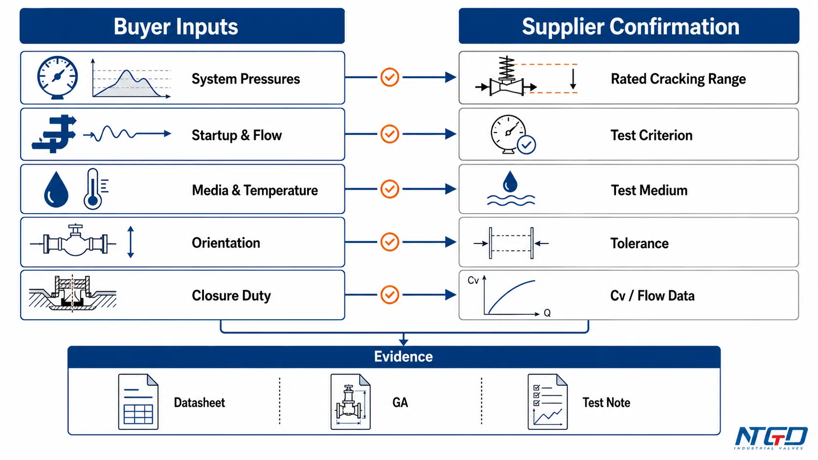
The final approval must be based on the complete offered configuration. A cracking-pressure value from another size, spring, trim, orientation, test medium, or detection method should not be assumed to apply.
Frequently Asked Questions About Check Valve Cracking Pressure
What is cracking pressure on a check valve?
It is the minimum forward differential pressure at which the first detectable forward flow begins. It is measured between the upstream and downstream sides of the valve and does not mean the valve is fully open.
Is opening pressure the same as cracking pressure?
Usually, the terms refer to the same initial-opening threshold. A datasheet may instead define opening pressure at a specific movement, lift, or flow condition, so the definition and test basis must be confirmed before comparing values.
What does 1 psi cracking pressure mean?
It means that, under the stated test conditions, upstream pressure must exceed downstream pressure by approximately 1 psi before the defined first-opening or first-flow criterion is reached.
The value should be compared with another valve only when the test medium, orientation, temperature, criterion, and tolerance are compatible. It does not mean that 1 psi is suitable for every application.
Is lower cracking pressure always better?
No. A lower threshold may help the valve open when differential pressure is limited, but it can also reduce closure force, resealing capability, or stability. The value must satisfy opening, minimum-flow stability, closure, and leakage requirements together.
How do engineers determine the required cracking pressure for an industrial check valve?
Engineers first establish the minimum forward differential available during startup and minimum-flow operation. They then account for orientation, valve mechanism, media, closure requirements, and tolerance.
A preliminary force-balance estimate may help, but final approval should use the maximum rated or tested cracking pressure for the offered configuration.
Is cracking pressure the same as pressure drop?
No. Cracking pressure is evaluated at the onset of flow, near zero flow. Operating pressure drop is measured or calculated at a stated flow rate.
A valve can have a low cracking pressure and still create a high operating pressure drop, or have favorable Cv while requiring more differential than the system can provide at startup.
What is the difference between cracking and resealing pressure?
Cracking pressure is associated with increasing forward differential as the valve begins to open. Resealing pressure is associated with decreasing differential as flow stops and the valve returns toward closure.
The two values may differ because of friction, spring behavior, hysteresis, seat contact, and the test criterion.
Can the cracking pressure of a spring-loaded check valve be changed?
Some spring-loaded designs can be supplied with different factory spring options or settings. That does not mean every valve can be adjusted in the field.
Changing the spring can also affect closure, resealing, leakage, travel, and operating stability. Any change should be evaluated and confirmed for the offered valve design.
Conclusion
Check valve cracking pressure confirms the initial opening threshold; it does not by itself confirm full-opening capacity or complete valve performance.
A complete evaluation must distinguish:
- first detectable flow from stable or more fully open operation;
- nominal spring setting from installed behavior;
- cracking pressure from resealing pressure and back pressure;
- opening threshold from operating pressure drop;
- and rated pressure boundary from opening differential.
The required value is governed by closing force or torque, effective pressure area, internal geometry, orientation, seat condition, service medium, and test definition.
A simplified force-over-area relationship can explain a translating mechanism, but it cannot replace rated or tested data for the offered configuration.
The correct cracking pressure is the range that enables reliable opening at the minimum system differential while also satisfying minimum-flow stability, operating pressure drop, closure, resealing, and leakage requirements.
Application / Specification Support
Prepare the service medium, temperature, startup pressure profile, minimum and normal flow, installation orientation, required opening condition, resealing expectation, leakage requirement, and operating pressure-drop limit before reviewing a cracking-pressure requirement.
The engineering review should then:
- compare the system’s minimum available differential with the offered valve’s maximum cracking pressure, including tolerance;
- confirm that the stated value applies to the actual orientation and test basis;
- review minimum-flow stability, resealing, leakage, and operating pressure drop as one package.
NTGD can use these application inputs to review whether a proposed check-valve configuration and cracking-pressure basis are consistent with the stated service conditions. The review should be completed against the offered valve’s actual datasheet, test basis, and approved configuration rather than an isolated nominal value.
After the application data and verification basis are defined, the relevant industrial check valve product family can be reviewed against the approved service conditions.
