Author Name: Bruce Zheng
Author Role: Co-Founder and Valve Engineer at NTGD Valve
Author Bio: Bruce Zheng is Co-Founder and Valve Engineer at NTGD Valve, focusing on industrial valve selection, application, and technical content for global B2B buyers.
Last Updated: May 24, 2026
Quick Answer: What Is the Difference Between a Two-Way and Three-Way Valve?
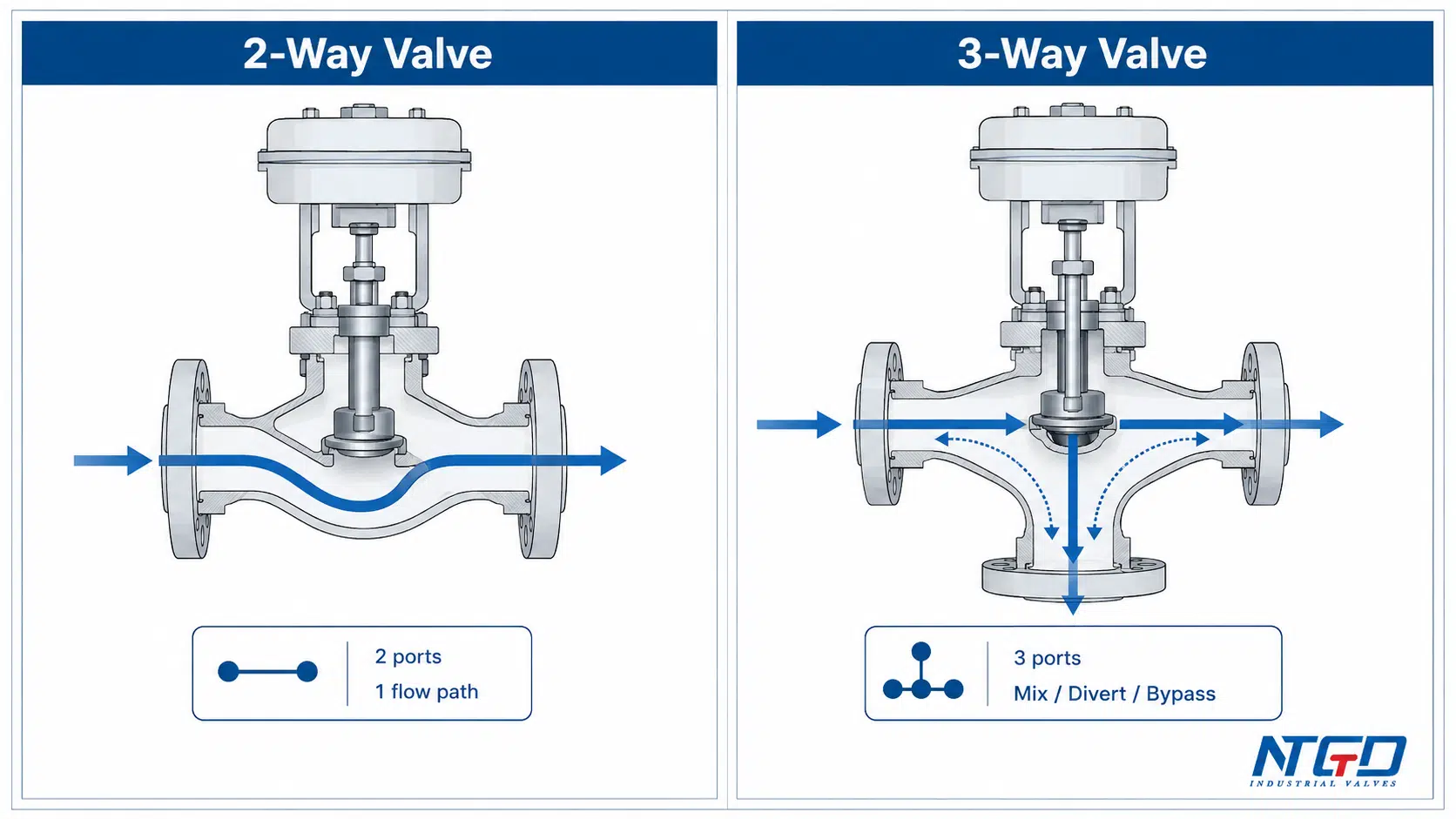
2-way valve vs 3-way valve selection in HVAC starts with the number of ports and the way each valve controls the flow path. A two-way valve has two ports and controls one flow path between an inlet and an outlet. It is commonly used for shutoff, isolation, or modulating flow through one branch, coil, or pipeline section. A three-way valve has three ports and can be arranged to mix, divert, or bypass flow depending on the valve design and port configuration.
In HVAC, hydronic, and chilled water systems, the choice is not only about the valve body. A two-way valve is commonly used in variable-flow systems, while a three-way valve is commonly used where constant circulation, bypass flow, or mixing is required. The real selection decision hinges on system flow strategy, pump design, and control sequence rather than valve body construction alone.
| If the system needs… | Common starting point | Why it matters |
|---|---|---|
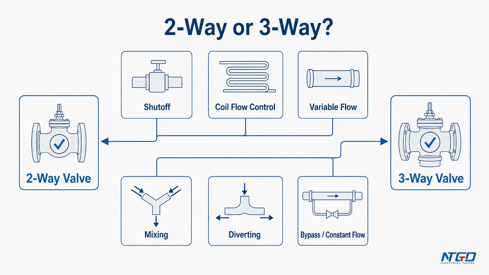
| Simple shutoff or isolation on one line | Two-way valve | Controls one flow path |
| Modulating flow through a coil or branch | Two-way valve | Varies flow based on load demand |
| Variable-flow chilled water or heating water control | Two-way valve, if the pump and controls are designed for it | Supports flow reduction and VSD pump control |
| Constant-flow circulation or bypass around a coil | Three-way valve | Maintains loop circulation through bypass |
| Mixing two streams into one outlet | Three-way valve | Combines two flow streams |
| Diverting one stream between two paths | Three-way valve | Redirects flow to different paths |
| Retrofit from 3-way to 2-way | Engineering review required | Confirm pump type, bypass need, minimum flow, and ΔP before replacement |
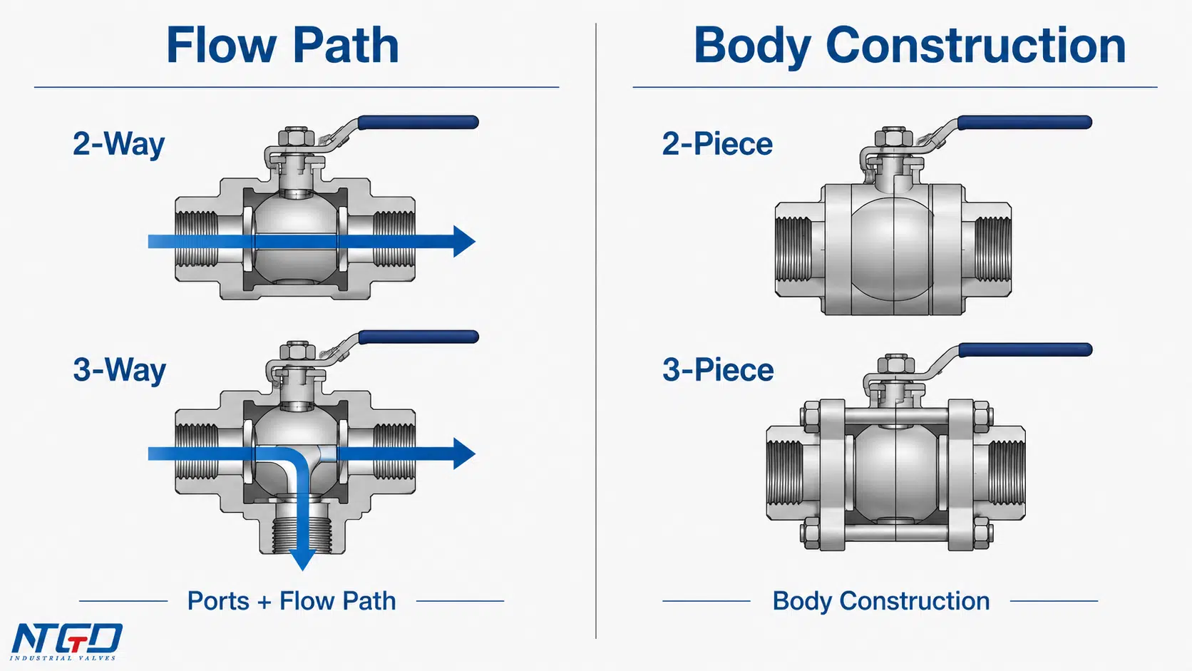
A two-way valve is not the same as a one-way check valve. A three-way valve is not the same as a three-piece ball valve. Two-way and three-way describe the flow path and port arrangement. Two-piece and three-piece describe body construction.
Key Differences Between 2-Way and 3-Way Valves
A quick comparison helps, but the important point is what the valve does to the system. In HVAC and hydronic service, the difference affects flow rate, pump behavior, coil control, bypass flow, and sometimes energy performance.
| Dimension | Two-Way Valve | Three-Way Valve |
|---|---|---|
| Number of ports | 2 ports | 3 ports |
| Basic flow path | One controlled flow path between inlet and outlet | Multiple possible paths through a common port and two branch ports |
| Main function | Shutoff, isolation, throttling, or modulating one line | Mixing, diverting, or bypassing flow |
| Typical HVAC role | Controls flow through a coil, branch, or terminal unit | Maintains circulation, mixes streams, or redirects flow through a bypass |
| System flow effect | Commonly supports variable-flow systems | Commonly supports constant-flow or bypass arrangements |
| Pump strategy | Often used with variable-speed pump systems when properly designed | Often used in legacy constant-volume systems or where minimum circulation is needed |
| Control complexity | Simpler piping and flow path | More complex port arrangement and control logic |
| Common mistake | Treating it like a one-way valve or ignoring differential pressure and close-off pressure | Ignoring port arrangement, mixing/diverting direction, or bypass effect |
| Energy impact | Can support pump energy savings in a properly designed variable-flow system with VSD control | Bypass or constant-circulation flow can reduce potential savings and may contribute to low ΔT if not controlled properly |
| Ball valve note | A two-way ball valve uses a ball bore to control one flow path | A three-way ball valve may use an L-port or T-port ball, depending on the required flow pattern |
The best choice depends on how the system is intended to control flow. A two-way valve is a strong starting point when the system is designed to reduce flow at part load. A three-way valve is a strong starting point when the system must keep circulation moving while redirecting or mixing flow.
Why “2-Way” Does Not Mean “One-Way”
A common mistake is describing a two-way valve as a valve that “allows flow in one direction only.” That wording can confuse a two-way valve with a check valve.
A two-way valve has two ports and controls one flow path between the inlet and outlet.
Depending on the valve design and the system, flow direction may matter for sealing, pressure drop, actuator force, or manufacturer installation requirements. But “two-way” itself refers to the port arrangement, not to a non-return function.
How Two-Way and Three-Way Valves Work
How a Two-Way Valve Works
A two-way valve has one inlet and one outlet. In a simple manual valve, it may be used to open or close flow. In an automated HVAC or hydronic system, it may modulate to control the amount of water flowing through a coil, branch, or terminal unit.
In a chilled water coil, for example, a two-way control valve can reduce chilled water flow when the cooling load drops. If the pumping system is designed for variable flow, that reduction in valve demand can allow the pump system to reduce flow as well. Without proper pump and control coordination, excessive valve closure can cause pressure spikes, unstable coil response, or close-off problems.
A two-way ball valve uses a drilled ball bore to open or close one flow path. In HVAC control service, however, the valve’s construction is only part of ball valve selection. The engineer also needs to consider the required control characteristic, actuator type, pressure differential, close-off pressure, and system flow strategy.
How a Three-Way Valve Works
A three-way valve has three ports. One port is commonly used as the common connection, while the other two ports connect to different flow paths. Depending on the design, the valve may be arranged for mixing, diverting, or bypass service.
A three-way valve can:
- mix two incoming streams into one outlet;
- divert one incoming stream between two outlets;
- redirect flow around a coil or equipment branch through a bypass line.
In HVAC systems, three-way valves are often used when the system needs to maintain circulation even when the coil or load does not require full flow. This is why three-way valves are frequently associated with constant-flow or older constant-volume hydronic systems.
Where Ball Valve Construction Fits
Two-way and three-way describe port and flow-path logic. Ball valve describes one possible valve construction.
A two-way ball valve can be used for simple shutoff or, with the correct design, for certain control duties. A three-way ball valve may use an L-port or T-port ball to create different flow paths. But this article focuses on the flow-control function in HVAC and hydronic systems, not on body-piece construction or detailed three-way ball valve product types.
This distinction matters because a two-way valve is not the same as a two-piece valve, and a three-way valve is not the same as a three-piece valve.
Mixing, Diverting, and Bypass: Why Three-Way Valves Are Different
A three-way valve is not simply “a two-way valve with one more port.” The third port changes what the valve can do in the piping system.
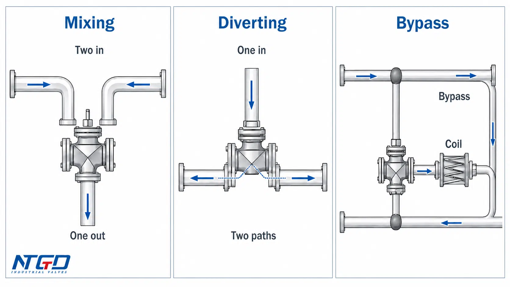
Mixing Service
In mixing service, two streams enter the valve and leave through one common outlet. This arrangement is used when the system needs to blend two fluid streams before sending the combined flow downstream.
In HVAC and hydronic systems, mixing may be used to blend supply and return water or to control the temperature entering a loop or coil. The exact piping arrangement must match the valve design. Not every three-way valve can be used in every mixing or diverting arrangement.
Diverting Service
In diverting service, one stream enters the valve and is directed toward one of two outlet paths. This can be used when the system needs to send flow either through a load or around it.
For example, a valve may divert chilled water toward a coil when cooling is needed, or toward a bypass path when the coil demand drops. The valve must be installed according to the port markings and the manufacturer’s flow arrangement.
Bypass Service in HVAC and Hydronic Systems
Bypass service is one of the most important reasons three-way valves appear in HVAC systems. When a coil does not need full heating or cooling, the valve can redirect flow through a bypass while maintaining circulation in the loop.
This can be useful in constant-flow systems or in systems where minimum circulation must be maintained. However, in a system designed for variable flow and variable-speed pumping, unnecessary bypass flow may reduce potential pump energy savings. In variable-flow chilled water systems, uncontrolled bypass flow can also contribute to low ΔT symptoms, meaning a reduced temperature difference between supply and return water, and reduce the benefit of variable-speed pumping.
The result depends on the system design, control sequence, and valve arrangement.
L-Port and T-Port Ball Valve Note
Some three-way ball valves use an L-port or T-port ball.
These internal bore patterns determine which ports can connect in each valve position. This is a useful concept, but it should not take over the article. L-port and T-port selection belongs to the detailed design of three-way ball valves. For this page, the key point is simpler: always verify the port arrangement, flow direction, and intended service before selecting or replacing a three-way valve.
2-Way vs 3-Way Control Valves in HVAC and Hydronic Systems
In HVAC, the difference between a two-way and three-way control valve becomes more important when the valve is controlled by an actuator and connected to a building automation system.
The valve does not work alone. It interacts with the pump, coil, piping layout, control sequence, and load demand.
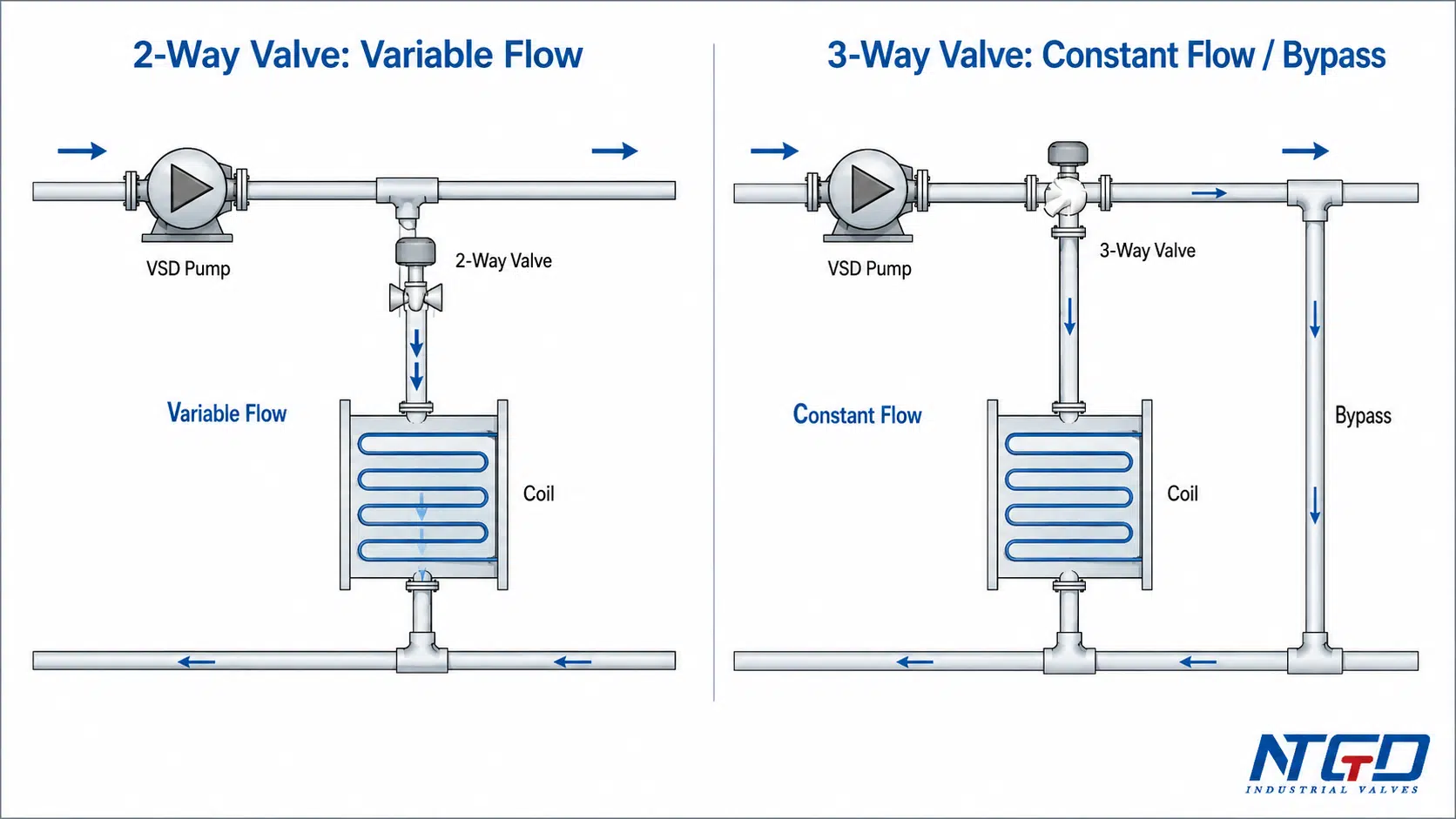
Two-Way Control Valves and Variable Flow
A two-way control valve usually controls flow through one coil, branch, or terminal unit. When the valve modulates toward the closed position, less water flows through that branch.
In a properly designed variable-flow chilled water or heating water system, this can help reduce total system flow at part load. When combined with variable-speed pump control, the pump may slow down as demand decreases.
This is one reason two-way valves are common in modern hydronic systems. In new or properly retrofitted variable-flow systems with VSD pumps and differential pressure control, a two-way valve is usually the preferred starting point. However, the system must be designed for this behavior. If many two-way valves close against a pump that is not controlled correctly, differential pressure can increase. The valve actuator must have enough close-off force for the expected pressure differential. The system may also need differential pressure control, minimum flow protection, or bypass provisions.
Three-Way Control Valves and Constant Flow
A three-way control valve can maintain a more constant circulation path by redirecting flow between the coil and bypass. When the coil needs full heating or cooling, more flow passes through the coil. When the load drops, more flow may pass through the bypass.
This arrangement is common in older constant-volume systems and some retrofit situations. The pump continues to circulate water even when the coil demand changes.
A three-way valve is not automatically less efficient or more efficient. Its value depends on why the system needs constant circulation. In some systems, maintaining flow protects equipment or keeps a loop stable. In other systems, unnecessary bypass flow can reduce the benefit of variable-speed pumping.
Building Automation and Actuator Signal Context
In automated HVAC systems, the valve position is often controlled by a thermostat, controller, or building automation signal. An actuated ball valve may drive a two-way or three-way flow path to modulate flow according to temperature demand.
For selection, the important question is not only “two-way or three-way?” It is:
- What is the control signal?
- Is the system variable flow or constant flow?
- What happens when several valves close?
- Does the pump need a minimum flow path?
- Can the selected actuator close against the expected pressure differential?
From a control-valve perspective, the 2-way vs 3-way decision is really a choice between variable-flow control and constant-flow or bypass control. That choice affects pump selection, bypass piping, actuator close-off requirements, and the realistic energy-saving potential of the system.
2-Way and 3-Way Valves in Chilled Water Systems
Chilled water systems are one of the clearest examples of why this comparison matters. A valve on an AHU coil, FCU coil, or terminal unit can affect not only local temperature control but also pump flow, bypass flow, and system stability.
Two-Way Valve on an AHU or FCU Coil
A two-way valve installed on a chilled water coil controls how much chilled water passes through that coil. When the cooling load is high, the valve opens more. When the load drops, the valve closes or modulates toward a lower flow position.
In a variable-flow system, this helps reduce chilled water flow through the coil when less cooling is required. If the pump system is designed with suitable control logic, variable-speed pumping can respond to the reduced flow demand.
This is why two-way valves are commonly used in modern chilled water systems. But the selection still needs engineering confirmation. The designer must check pressure differential, close-off pressure, valve authority, actuator sizing, and the pump control sequence.
Three-Way Valve with Bypass Around a Coil
A three-way valve near a chilled water coil can redirect water through the coil or through a bypass path. When the coil needs cooling, more water passes through the coil. When the coil demand drops, more water may bypass the coil while the loop circulation continues.
This can help maintain flow in constant-volume systems. It can also be useful where minimum circulation is required. In many older systems, three-way valves were used because the pumping strategy expected a relatively constant flow path.
The drawback is that bypassed water may continue circulating even when it does not perform useful cooling. In systems designed for variable flow, this can reduce pump energy savings or create temperature-control problems if the bypass arrangement is not properly designed.
Retrofit Warning: Do Not Replace a 3-Way Valve with a 2-Way Valve by Appearance Alone
Replacing a three-way chilled water valve with a two-way valve may look simple, but it can change the hydraulic behavior of the system.
For example, if an old constant-volume system uses a three-way valve to maintain circulation and the valve is replaced by a two-way valve without checking pump control or minimum flow, the pump may see rising differential pressure as terminal valves close. The result may be unstable coil control, pressure alarms, or valves that cannot fully close under load.
Before replacement, confirm at least the following:
- whether the original system was constant flow or variable flow;
- whether the pump is constant speed or variable speed;
- whether the system requires minimum flow;
- whether a bypass path is still needed;
- the expected differential pressure across the valve;
- actuator close-off pressure;
- the control sequence;
- port marking, flow direction, and manufacturer datasheet limits.
A two-way valve may be the right upgrade in some variable-flow retrofit projects. But it should not be selected only because it looks simpler or appears more energy efficient.
When to Use a 2-Way Valve vs a 3-Way Valve
The best valve choice depends on system purpose. Use the table below as a starting point, not as a substitute for engineering review.
| System or Requirement | Better Starting Point | Why |
|---|---|---|
| Simple shutoff or isolation | 2-way valve | It controls one flow path |
| Modulating flow through one coil or branch | 2-way valve | It can reduce or increase flow through that branch |
| New variable-flow chilled water system | Usually 2-way valve | It can support reduced flow when paired with suitable pump controls |
| Variable-speed pump system | Usually 2-way valve | It allows flow demand to fall when loads decrease |
| Existing constant-volume system | Often 3-way valve | It can maintain circulation through a bypass path |
| Minimum flow requirement | 3-way valve or dedicated bypass arrangement | It keeps a circulation path available |
| Mixing supply and return water | 3-way mixing valve | It combines two streams |
| Diverting flow between coil and bypass | 3-way diverting valve | It redirects one stream between two paths |
| Retrofit from 3-way to 2-way | Engineering review required | Check pump strategy, minimum flow, bypass need, and ΔP before replacement |
| Unclear legacy piping layout | Start with drawings and port marking verification | Valve appearance alone is not enough for selection |
Which Is Better?
Neither valve is universally better. A two-way valve is usually better for simple shutoff, isolation, or variable-flow coil control. A three-way valve is usually better for mixing, diverting, bypass, or constant-flow arrangements. The better choice depends on the system design.
A good selection starts with the system strategy first, then confirms the valve type, port arrangement, actuator capability, and datasheet limits.
Common Wrong-Choice Consequences
A wrong valve choice does not always cause immediate failure. In many cases, the system still runs, but with poor control, unstable flow, higher energy use, or premature valve and actuator stress.
Using Two-Way Valves in the Wrong Constant-Flow System
If a two-way valve is installed in a system that was designed for constant flow, the valve may close against a pump that still expects circulation. Depending on the piping and pump control, this can cause:
- rising differential pressure;
- pump dead-head risk;
- actuator close-off problems;
- ghost flow, meaning small unintended leakage or flow through a valve that is supposed to be closed, causing a coil or terminal unit to continue heating or cooling slowly;
- noise or unstable control;
- poor temperature response at the coil.
This does not mean two-way valves are unsafe. It means the system must be designed to handle reduced flow.
Using Three-Way Valves in the Wrong Variable-Flow System
If a three-way valve is used in a system intended to reduce flow at part load, bypass flow may continue circulating water even when the load does not require it.
Possible results include:
- reduced pump energy savings;
- unnecessary circulation;
- low ΔT risk in chilled water systems;
- return water temperature problems;
- unstable loop control;
- lower overall system efficiency.
This does not mean three-way valves are outdated. They remain useful in constant-flow, mixing, diverting, bypass, and retrofit applications where the hydraulic design requires them.
Mixing and Diverting Port Arrangement Errors
Three-way valves are especially sensitive to port arrangement. A valve intended for mixing may not be suitable for diverting service unless the manufacturer specifically allows it. A valve installed with the wrong common port can behave very differently from the designer’s intent.
Common consequences include:
- unstable leaving water temperature;
- valve chatter;
- flow through the wrong path;
- poor coil response;
- actuator hunting;
- premature seat or stem wear.
Always confirm the valve drawing, port marking, flow direction, and datasheet before installation.
2-Way / 3-Way vs 2-Piece / 3-Piece Ball Valves
This is one of the most important terminology clarifications for ball valves.
| Term | What it means | What it does not mean |
|---|---|---|
| 2-way valve | A valve with two ports and one controlled flow path | Not the same as a 2-piece body |
| 3-way valve | A valve with three ports and mixing, diverting, or bypass capability | Not the same as a 3-piece body |
| 2-piece ball valve | A ball valve body construction with two main body pieces | Not a flow-path classification |
| 3-piece ball valve | A ball valve body construction with three body sections | Not a three-port valve by default |
A two-piece ball valve can be two-way. A three-piece ball valve can also be two-way. The body construction does not define the number of flow ports.
Confusing flow-path terms with body-construction terms can lead to incorrect specifications, wrong image selection, and misunderstanding of the valve’s actual port arrangement.
Final Fit-Check Before Specifying a 2-Way or 3-Way Valve
Before selecting a two-way or three-way valve for an HVAC, hydronic, or chilled water project, confirm both the system requirement and the valve design limits.
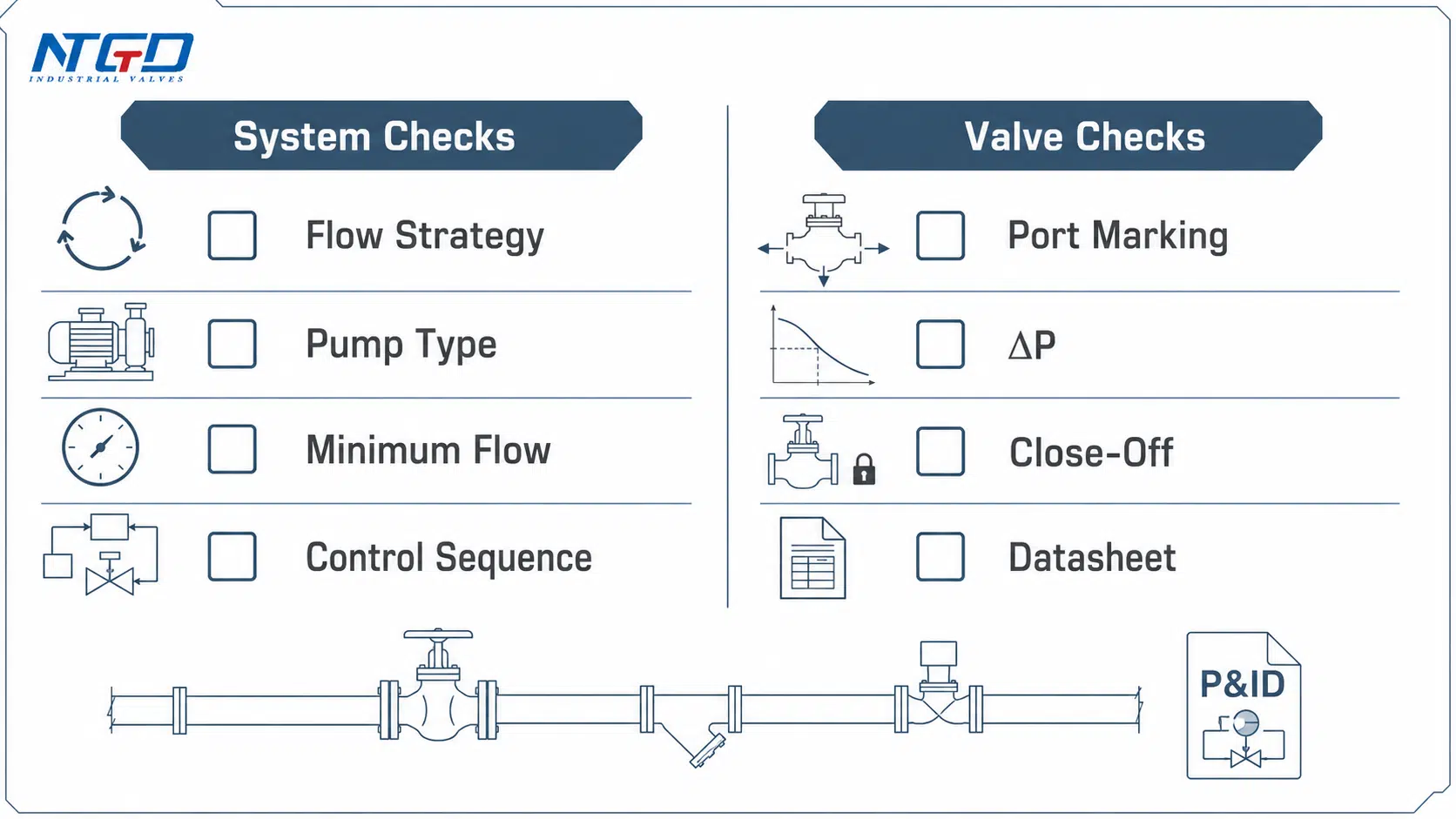
System and Control Checks
Review the system conditions first, especially flow strategy, differential pressure, and any minimum-flow or bypass requirement:
| Check Item | Why it matters |
|---|---|
| Variable-flow or constant-flow system | Determines whether reduced flow or bypass flow is expected |
| Pump type | Constant-speed and variable-speed systems behave differently |
| Minimum flow requirement | Some systems require a circulation path even at low load |
| Coil or terminal unit duty | Determines whether flow should stop, modulate, mix, or bypass |
| Control sequence | Valve action must match controller logic |
| Actuator type and signal | Manual, on/off, floating, or modulating control affects selection |
| Differential pressure | Affects valve authority, noise, and close-off |
| Existing piping layout | Especially important in retrofit work |
Valve and Datasheet Checks
Check the valve itself:
| Check Item | Why it matters |
|---|---|
| Port marking | Confirms common port and branch port arrangement |
| Flow direction | Some valves have preferred or required flow direction |
| Mixing or diverting suitability | Not all three-way valves are suitable for both services |
| Close-off pressure | Ensures the actuator can shut the valve tightly under the maximum expected differential pressure. If the close-off rating is too low, the valve may not fully close, causing leakage, unstable control, or seat wear |
| Pressure and temperature rating | Must match service conditions |
| Media compatibility | Chilled water, heating water, glycol, or other media may affect materials |
| Connection type | Flanged, threaded, welded, or other ends must match the piping |
| Body, trim, and seat design | Affects sealing, throttling behavior, corrosion resistance, and service suitability |
Performing these checks early prevents most of the misapplication issues described above, especially pressure-related leakage, wrong bypass behavior, and incorrect mixing or diverting flow.
What to Include in an RFQ
For a clearer valve recommendation, prepare the following information before sending an RFQ:
- system flow strategy: variable flow, constant flow, or retrofit;
- service medium, such as chilled water, heating water, glycol water, or process fluid;
- valve size and connection type;
- pressure class or design pressure;
- design temperature;
- manual or actuated operation;
- actuator signal, if required;
- mixing, diverting, bypass, isolation, or coil-control duty;
- expected differential pressure and close-off requirement;
- drawing, P&ID, or piping sketch if available.
This information supports a more complete industrial valve selection process and helps avoid a common mistake: selecting a valve by port count alone without confirming how it will behave in the actual system.
FAQ: 2-Way vs 3-Way Valves
What is the difference between a two-way valve and a three-way valve?
A two-way valve has two ports and controls one flow path between an inlet and outlet. A three-way valve has three ports and can mix, divert, or bypass flow depending on its internal design and port arrangement.
When should I use a 2-way valve instead of a 3-way valve?
Use a 2-way valve when you need to control flow through one line, branch, or coil. It is commonly used in variable-flow HVAC systems where reducing flow at part load is part of the system design.
Which is better, a 2-way or 3-way valve?
Neither is always better. A 2-way valve is usually better for simple shutoff, isolation, or variable-flow coil control. A 3-way valve is usually better for mixing, diverting, bypass, or constant-flow arrangements. The better choice depends on the system design.
What is a 3-way valve used for in HVAC?
In HVAC systems, a 3-way valve is often used to mix water streams, divert flow, or bypass a coil while maintaining circulation. It is common in hydronic and chilled water systems that require constant flow or controlled bypass.
Can a 3-way valve be used for both mixing and diverting?
Some 3-way valves can be arranged for mixing or diverting, but not all designs are interchangeable. Always confirm the manufacturer’s datasheet, port marking, and installation instructions before using a 3-way valve for a specific flow pattern.
Is a 3-way valve the same as a 3-piece ball valve?
No. A 3-way valve describes port arrangement and flow path. A 3-piece ball valve describes body construction. A valve can have a three-piece body and still be a two-way valve if it has only two flow ports.
Is a 2-way valve the same as a 2-piece ball valve?
No. A 2-way valve has two ports and controls one flow path. A 2-piece ball valve has a body made from two main body sections. These terms describe different valve features and should not be mixed in specifications.
What is the difference between a 2-way and 3-way diverter?
A 2-way valve controls flow through one path. A 3-way diverter valve can direct one inlet flow toward one of two outlet paths. In HVAC, this may be used to send flow through a coil or through a bypass path.
Can I replace a 3-way chilled water valve with a 2-way valve?
Sometimes, but not by appearance alone. A replacement decision must consider the original pumping strategy, minimum flow requirement, bypass function, differential pressure, actuator close-off pressure, and control sequence. Some retrofits require system changes before replacing a 3-way valve with a 2-way valve.
Do all 3-way valves have the same flow pattern?
No. Many 3-way valves look similar from the outside, but the internal flow path can be different. For example, an L-port and a T-port ball can connect the same three pipe ends in very different ways.
A valve with the correct end connections can still fail to provide the intended mixing or diverting function if the internal port pattern is wrong. Always verify the drawing, port marking, and datasheet.
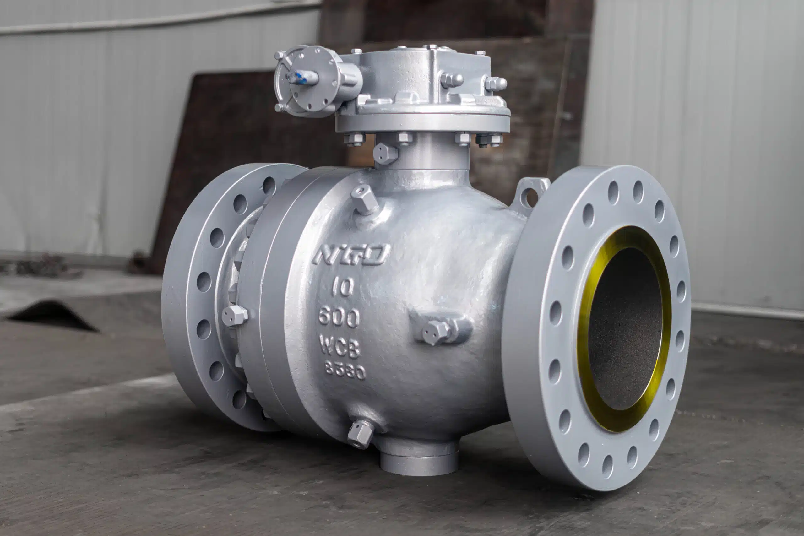
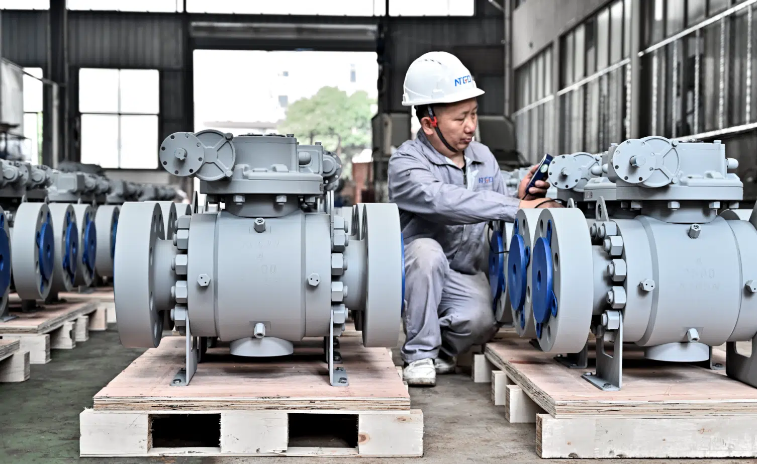
The video below is not a 2-way vs 3-way HVAC tutorial, but it shows how NTGD verifies industrial ball valves under real hydrostatic test conditions before delivery.
Conclusion
The difference between a 2-way valve and a 3-way valve starts with ports and flow paths, but the correct selection depends on the system flow strategy. A two-way valve controls one flow path and is commonly used for shutoff, throttling, or variable-flow coil control. A three-way valve has three ports and can mix, divert, or bypass flow, which makes it useful in constant-flow, bypass, and mixing applications.
For HVAC, hydronic, and chilled water systems, the valve should be selected according to the pumping strategy, coil control requirement, bypass need, differential pressure, actuator close-off capability, and port arrangement. Do not choose only by valve appearance, old photos, or the words “two-piece” and “three-piece.” Two-way and three-way refer to flow paths. Two-piece and three-piece refer to body construction.
Before specification or replacement, confirm the datasheet, port marking, flow direction, actuator capacity, close-off pressure, and actual piping arrangement.
For an HVAC, hydronic, or chilled-water project, share your project details with the valve engineering team, including system flow strategy, service medium, actuator requirement, and P&ID details, so the 2-way or 3-way solution can be checked against the actual piping and control conditions.
