Author Name: Bruce Zheng
Author Role: Co-Founder and Valve Engineer at NTGD Valve
Author Bio: Bruce Zheng is Co-Founder and Valve Engineer at NTGD Valve, focusing on industrial valve selection, application, and technical content for global B2B buyers.
Last Updated: June 2, 2026
A flanged butterfly valve is a quarter-turn butterfly valve designed with flanged ends for bolted connection to matching pipe flanges. It is commonly used in industrial piping systems where the valve must be securely mounted between pipeline sections while still providing compact operation, fast opening and closing, and practical shutoff or throttling service.
Unlike a wafer-style butterfly valve that is clamped between pipe flanges, a flange type butterfly valve has a valve body connection interface designed for bolting to the pipeline flange system. This makes the butterfly valve flange connection an important part of valve selection, not just a naming detail.
For engineers, buyers, MRO teams, and project purchasers, the main question is not only “what is a flanged butterfly valve?” but also whether the flange standard, bolt-hole pattern, gasket or liner design, seat material, disc clearance, pressure class, and actuator arrangement match the actual pipeline service. A mismatch here often appears during installation or early operation as leakage, high torque, poor sealing, or delayed commissioning.
This guide explains how flanged butterfly valves work, how the flanged connection is built, which components affect selection, where these valves are commonly used, and what should be checked before sending an RFQ.
What Is a Flanged Butterfly Valve?
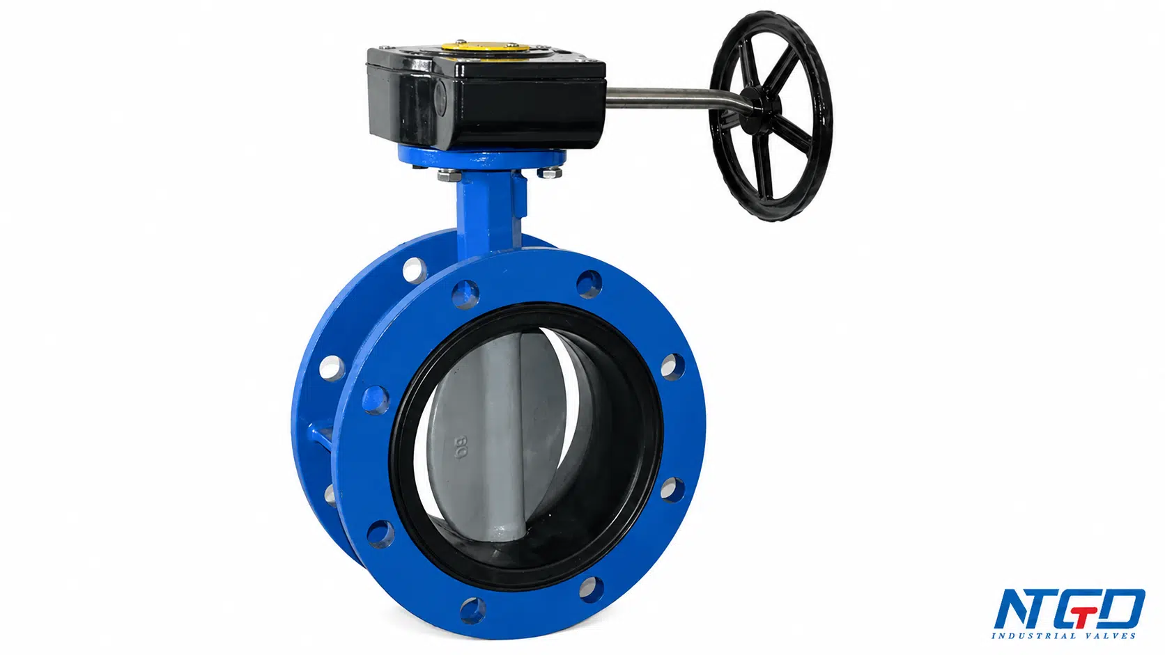
A flanged butterfly valve is a butterfly valve with flanged connection ends on the valve body. These flanges allow the valve to be connected to matching pipe flanges using bolts, studs, and nuts. Flow is controlled by a rotating disc that turns approximately 90 degrees between the open and closed positions.
The following table clarifies how different search expressions are usually understood in valve specification and inquiry communication. These terms often refer to the same general valve category, but the exact body design, flange standard, and connection details still need to be confirmed before purchase.
| Term | Practical meaning |
|---|---|
| Flanged butterfly valve | A butterfly valve with flanged ends for bolted pipeline connection |
| Flange type butterfly valve | Another common way to describe a butterfly valve by its flange-end connection style |
| Butterfly valve with flange | A natural search expression meaning a butterfly valve designed with flanged connection ends |
| Butterfly valve with flanges | A similar expression emphasizing that the valve body has flange connection surfaces |
| Butterfly valve flange type | A specification-style term identifying the valve by its flange-end connection style, often used to distinguish it from wafer or lug types |
The word flanged affects how the valve is installed, how load is transferred to the piping system, how sealing is achieved at the pipe connection, and what information must be checked before purchase.
A flanged butterfly valve is typically selected when the piping system requires a stable bolted connection, larger pipe size support, easier alignment than some compact connection styles, or a more robust interface for industrial service. However, the valve still needs to be selected according to the actual pressure, temperature, media, seat material, body material, flange standard, and operating method.
How the Flanged Butterfly Valve Connection Works
The flanged butterfly valve connection is built around the interface between the valve body flanges and the pipe flanges. The valve does not simply “fit into a pipe.” It must match the pipeline connection standard and be installed so that the disc, seat, sealing surface, and bolts are not stressed incorrectly.
A typical flanged connection includes:
| Connection item | Role in the connection | Why it matters |
|---|---|---|
| Valve body flange | Provides the valve-side bolted connection surface | Must match the pipeline flange standard and drilling pattern |
| Pipe flange | Provides the mating pipeline connection surface | Poor matching can create installation difficulty or uneven load |
| Bolts, studs, and nuts | Provide clamping force between the valve and piping | Uneven tightening can distort sealing surfaces or increase torque |
| Flange face | Contact area between mating connection surfaces | Surface condition affects external leakage risk |
| Gasket, seat, or liner interface | Provides or supports sealing at the connection | Depends on valve design and manufacturer instruction |
| Disc clearance | Space needed for the disc to rotate without interference | Incorrect pipe bore or misalignment may cause rubbing or damage |
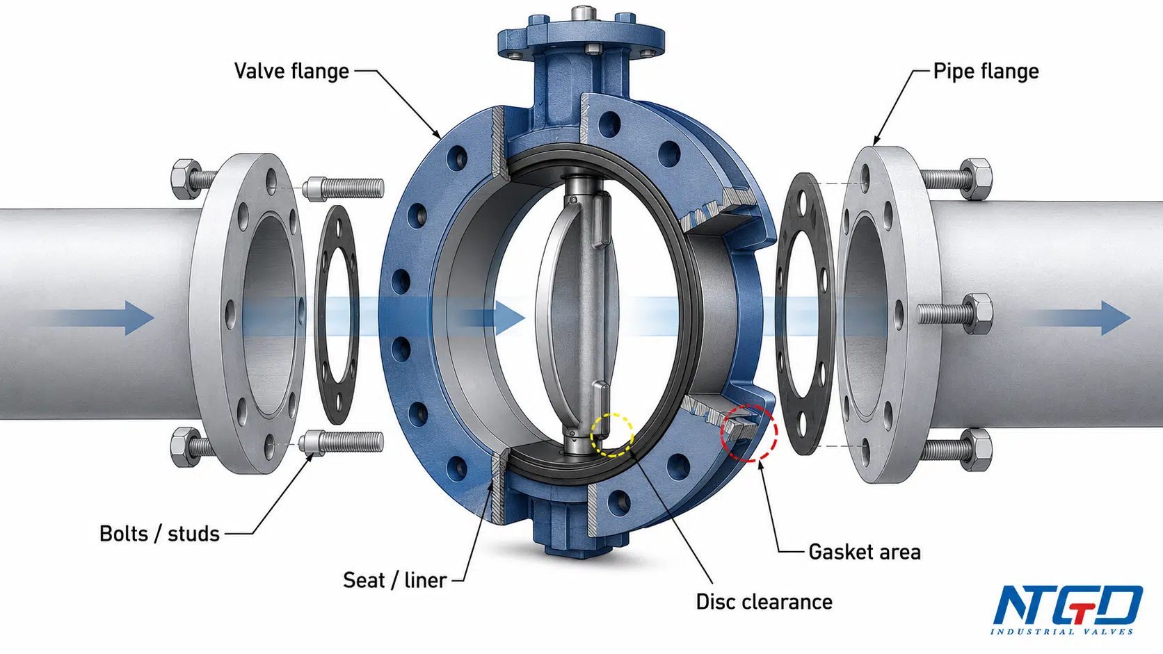
Valve Flanges and Pipe Flanges
The valve body flanges must match the pipe flange standard, size, pressure rating, drilling pattern, and project standard. If the flange standard or bolt-hole pattern does not match, the valve may not be installable without rework.
This is why a flanged end butterfly valve should not be selected by nominal size alone. Size, pressure class, flange standard, face-to-face dimension, and connection design should all be checked together.
Bolts, Studs, Nuts, and Flange Faces
Bolts, studs, and nuts create the clamping force that holds the valve and pipe flanges together. The flange faces provide the mating surfaces. If the bolts are tightened unevenly or the flange faces are not aligned, the sealing interface may be loaded unevenly.
The risk is usually seen as external leakage, seat or liner distortion, high operating torque, or repeated maintenance after startup.
Gasket, Seat, or Liner Interface
Some flanged butterfly valves use a separate gasket in the bolted flange connection between the valve and pipe flange. Others rely on the valve seat or liner design to provide the sealing interface. This depends on the valve design and the manufacturer’s installation instructions.
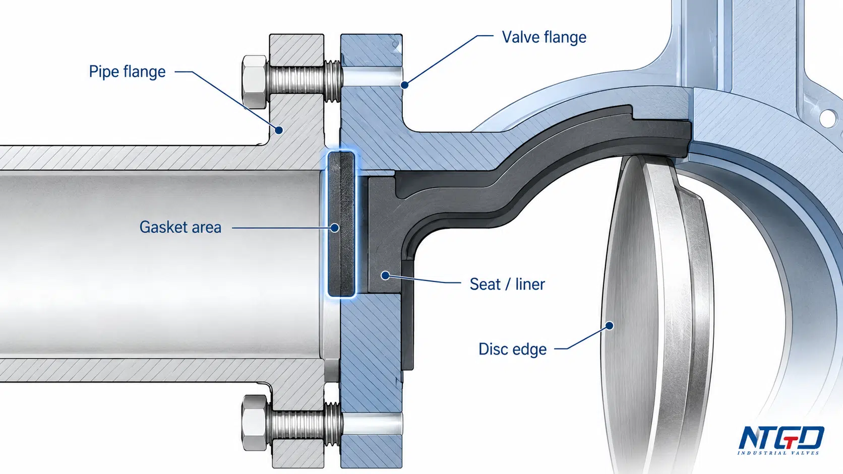
A buyer should not assume that every flanged butterfly valve requires the same gasket arrangement. The gasket or liner interface should be confirmed from the valve datasheet, project specification, and manufacturer instruction before installation. A wrong sealing interface can cause external leakage, over-compression, liner distortion, or installation delay.
Flange Matching and Disc Clearance
Disc clearance is often overlooked. When the butterfly valve opens, the disc rotates into the flow path. If the pipe internal diameter, flange bore, gasket arrangement, or pipe alignment interferes with the disc movement, the valve may become hard to operate or the disc edge may be damaged.
Once the connection principle is understood, the buyer should verify all critical parameters linking the valve to the pipeline system. A detailed RFQ checklist is provided later in this guide to help confirm these items before inquiry.
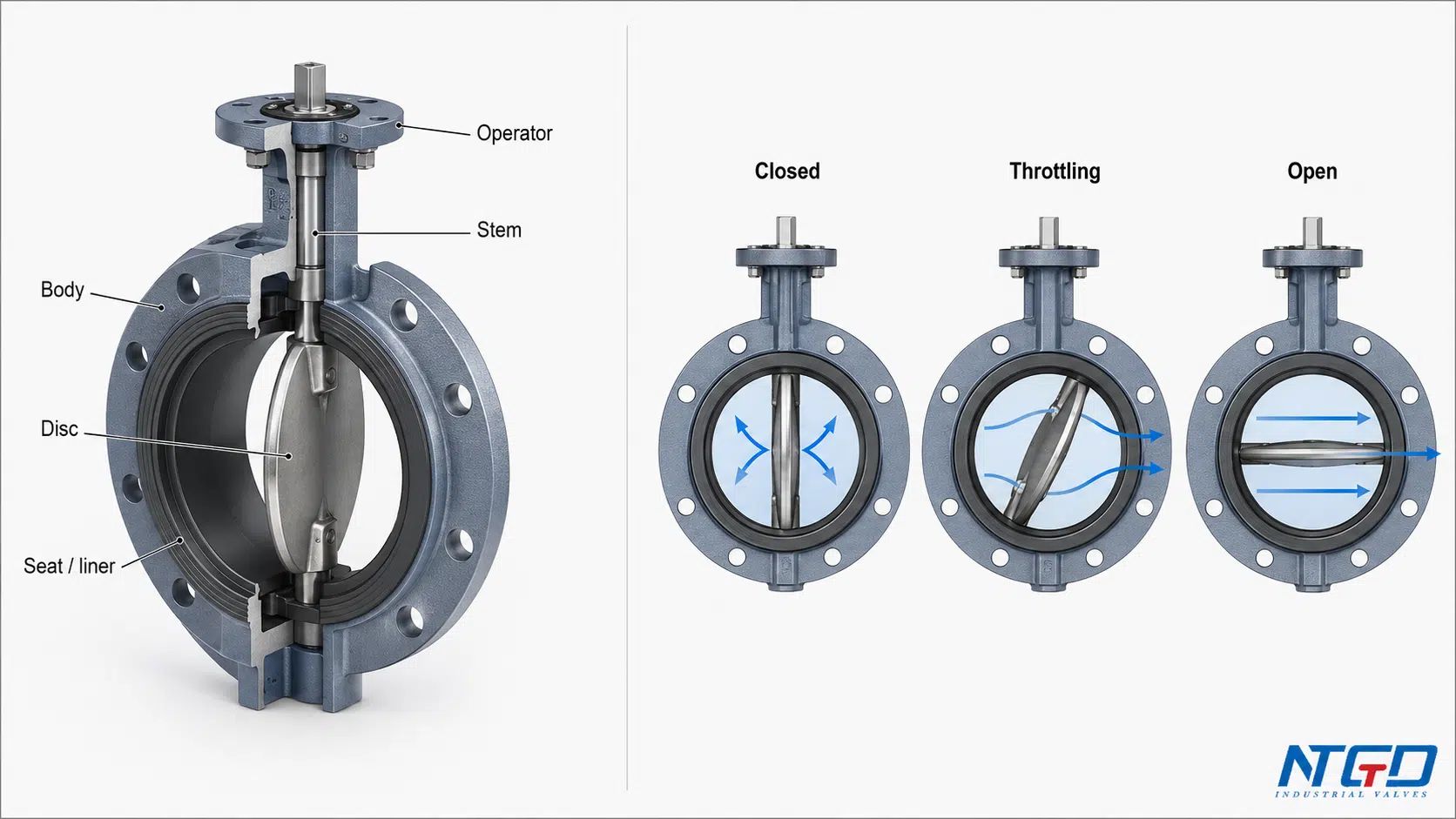
Main Components and Working Principle
A flanged butterfly valve combines the compact quarter-turn motion of a butterfly valve with a bolted flange-end connection. The main components should not be reviewed as isolated parts. Each component affects sealing, torque, pressure drop, compatibility, or installation reliability.
| Component | Basic function | Selection impact |
|---|---|---|
| Body | Pressure boundary and flange support | Body material, pressure class, flange standard, bolt-hole pattern, and face-to-face dimension must match the pipeline |
| Disc | Rotating closure element in the flow path | Disc material, disc edge condition, pressure drop, throttling duty, and media compatibility affect service life |
| Seat or liner | Sealing surface between disc and body | Media, temperature, shutoff requirement, torque, and wear resistance influence selection |
| Stem | Transfers torque from operator to disc | Torque requirement and actuator sizing depend partly on stem and disc load |
| Packing | Helps seal around the stem | Affects external leakage risk at the stem area |
| Gasket or flange seal | Supports sealing at the valve-pipe interface | Depends on flange face condition, seat or liner design, gasket requirement, and manufacturer instruction |
| Operator or actuator | Opens, closes, or modulates the valve | Manual, gearbox, pneumatic, electric, or hydraulic operation should match torque and control needs |
Body and Flanged Ends
The body supports the internal components and provides the flanged connection interface. For flanged butterfly valves, the body is not only a pressure boundary but also part of the installation geometry. The flange drilling, face-to-face length, and connection standard are therefore part of the selection decision.
Disc, Stem, and Seat
The disc rotates to open, close, or partially restrict flow. The stem transmits torque from the hand lever, gearbox, or actuator to the disc. The seat or liner provides the sealing surface when the disc closes.
The disc remains in the flow path even when the valve is fully open. This is one reason butterfly valves are compact and fast to operate, but it also means pressure drop and disc wear must be considered in some services.
How the Disc Opens, Closes, and Throttles Flow
When the valve is open, the disc turns roughly parallel to the flow direction. When the valve is closed, the disc turns perpendicular to the flow path and presses against the seat or sealing surface.
A flanged butterfly valve can be used for shutoff service and, in some applications, throttling service. However, throttling suitability should be checked against pressure drop, flow velocity, vibration, seat wear, and the control accuracy expected by the system. It should not be treated as a universal control valve for every flow-control duty.
Flanged Butterfly Valve Configurations: Operation, Seat, and Offset Design
Flanged butterfly valves may be configured by operation method, seat design, and disc/stem offset geometry. These are not the same as broader butterfly valve types. For this page, the focus is only on configurations that affect flange-end valve selection.
Operation Options
| Operation type | Best used when | Check before RFQ |
|---|---|---|
| Lever operation | Smaller size, lower torque, simple manual service | Handle clearance, locking requirement, operator access |
| Gearbox operation | Larger size or higher torque service | Gear ratio, handwheel space, mounting direction |
| Pneumatic actuator | Frequent open/close operation or automation | Air supply, fail position, control accessories |
| Electric actuator | Remote operation or controlled movement | Voltage, control signal, enclosure, duty cycle |
| Hydraulic actuator | High torque or special service | Hydraulic power unit, control logic, maintenance access |
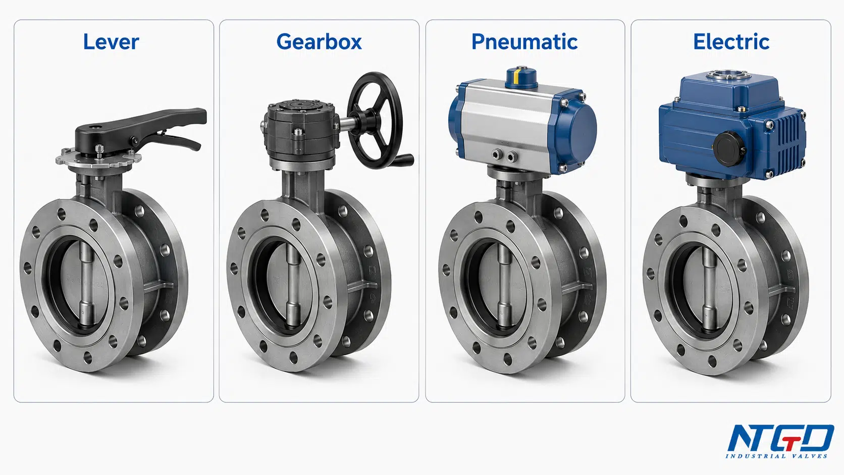
Manual operation is simple and cost-effective, but it may not be practical for high torque, large size, remote location, or frequent cycling. Actuated flanged butterfly valves are more suitable when the valve needs to operate automatically, respond to a control signal, or be integrated into a plant control system.
Concentric, Double Offset, and Triple Offset Designs
| Design | Typical purpose | Boundary |
|---|---|---|
| Concentric | General soft-seated service | Common for many water, HVAC, and utility applications, but not suitable for every high-temperature or severe-duty service |
| Double offset | Reduced seat friction and improved wear behavior | Selection is driven by seat wear, duty cycle, and sealing requirement, not by the body connection type |
| Triple offset butterfly valve | Metal-seat or severe-service potential | Requires verification of pressure-temperature envelope, leakage requirement, torque, and material compatibility |
Double offset and double flanged should not be confused. Double offset butterfly valve design describes the disc and stem geometry. Double flanged describes a body connection configuration. Mixing these terms in an RFQ can lead to wrong design parameters, delayed quotation, or a valve that does not match the intended service.
Seat and Sealing Boundary
Soft-seated designs are often selected for general shutoff where the media, temperature, and pressure are within the seat material’s capability. Metal-seated or triple-offset designs may be considered for higher temperature, higher pressure, abrasive, or severe service, but the exact suitability must be confirmed from the valve datasheet and project specification.
How to Specify a Flanged Butterfly Valve Before RFQ
Specifying a flanged butterfly valve is not just a paperwork step. Missing or incorrect data, such as the wrong flange standard, unsuitable seat material, incomplete media data, or unclear actuator requirement, may lead to installation failure, leakage, high operating torque, or unexpected maintenance cost.
The checklist below converts common field problems into pre-RFQ verification points.
| RFQ item | Why it matters | Buyer should confirm |
|---|---|---|
| Valve size | Pipeline compatibility | DN / NPS and pipeline bore condition |
| Pressure class | Body and flange rating | PN / Class / project rating |
| Flange standard | Installation matching | ASME, EN, DIN, JIS, or project standard as applicable |
| Bolt-hole pattern | Flange compatibility | Drilling pattern and bolt size compatibility |
| Face-to-face dimension | Pipeline fit | Drawing, datasheet, or project requirement |
| Body material | Pressure boundary and corrosion resistance | Ductile iron, carbon steel, stainless steel, or confirmed material |
| Disc material | Media contact and wear | Corrosion, erosion, and compatibility with media |
| Seat or liner material | Shutoff, temperature, and torque | EPDM, PTFE, metal seat, or confirmed design |
| Media | Compatibility | Water, wastewater, air, chemical, slurry-adjacent fluid, or other service |
| Temperature | Seat and material limit | Operating and design temperature |
| Shutoff or leakage requirement | Defines sealing expectation | Project shutoff requirement or leakage expectation |
| Operation method | Control and torque | Lever, gearbox, pneumatic, electric, or hydraulic actuation |
| Gasket / liner requirement | Flange sealing | Manufacturer instruction and project specification |
| Installation space | Access and disc clearance | Handle / actuator space and pipe bore clearance |
| Project compliance requirement | Documentation and approval | API 609, CE, ATEX, FDA, or other project-specific requirements if applicable |
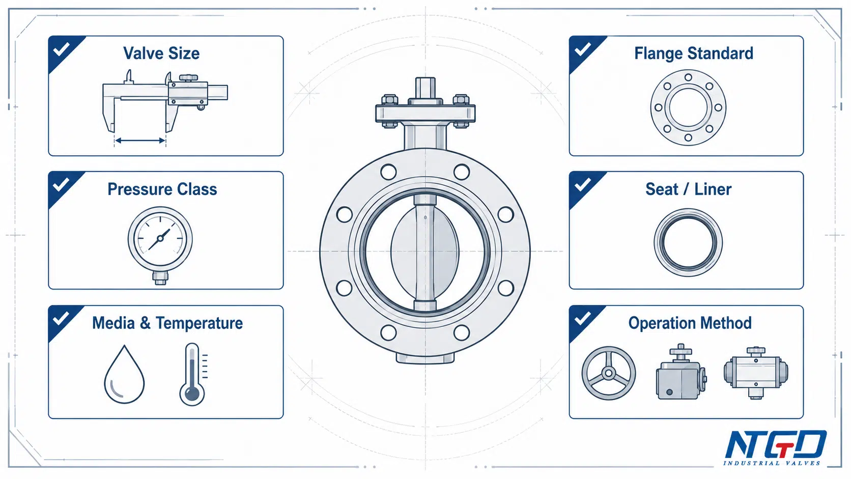
For broader butterfly valve selection, the highest-risk items are usually flange standard, pressure class, seat or liner material, media and temperature, and actuator requirement. These should be confirmed before comparing price or delivery time.
Where Flanged Butterfly Valves Are Used
Flanged butterfly valves are commonly selected where a compact quarter-turn valve is needed but the piping system requires a stronger bolted connection than a wafer-style arrangement. Instead of only listing industries, the application should be reviewed by service condition.
| Application | Why a flanged connection may be selected | Key checks | Caution / when to verify another option |
|---|---|---|---|
| Municipal water and wastewater | Stable bolted connection for larger pipeline systems | Seat material, corrosion, flange standard, actuator need | Verify corrosion, solids, and seat wear if water quality is variable |
| HVAC and cooling water | Compact operation and practical isolation or balancing | Temperature, seat material, space, actuator | Space-limited systems may require a more compact connection style |
| Power and utility water | Large-line isolation or control in plant utility systems | Pressure class, vibration, actuator sizing | Confirm pressure-temperature rating and operating frequency |
| Mining and slurry-adjacent service | Robust installation may be needed in difficult environments | Abrasion, solids content, disc and seat material | High solids or hard abrasive media may require a different valve design |
| Chemical service | Flanged connection supports industrial piping layouts | Corrosion resistance, temperature, seat compatibility, and possible stainless steel butterfly valve route | Chemical compatibility must be verified as a material combination, not by body material alone |
| Food and pharmaceutical utilities | Cleanability and sealing requirements may be important | Material, project requirement, cleaning process | Confirm whether the valve design and materials match cleaning and hygiene requirements |
| Pulp and paper | Utility and process fluids often require practical isolation | Media solids, seat wear, actuator requirement | Fiber buildup or solids may affect seat sealing and torque |
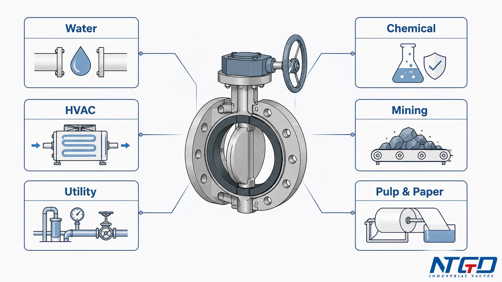
A flanged butterfly valve can be a strong fit for many industrial services, but the correct choice depends on the full system: media, temperature, pressure, pipeline standard, operation frequency, and maintenance access.
Advantages and Limitations of Flanged Butterfly Valves
A flanged butterfly valve should be selected as an engineering trade-off, not simply because it is “stronger” or “better” than other connection styles.
| Benefit | Why it helps | Corresponding limitation / caution |
|---|---|---|
| Stable bolted connection | Helps create a rigid interface with matching pipe flanges | Usually heavier and requires more installation space than wafer-type valves |
| Suitable for larger industrial lines | Flanged ends can support robust pipeline installation | Initial cost and installation complexity may be higher |
| Fast quarter-turn operation | Disc movement allows quick opening and closing | Not ideal for every high-precision flow control application |
| Compact compared with many linear-motion valves | Short body and simple rotation save space in many layouts | The disc remains in the flow path and can create pressure drop |
| Available with manual or actuated operation | Can match simple or automated systems | Actuator torque, fail position, control signal, and space must be confirmed |
| Can support shutoff and limited throttling | Useful in many utility and process services | Throttling must be checked against pressure drop, velocity, vibration, and seat wear |
| Easier specification support for industrial piping | Flanged standards and drawings help project documentation | Flange mismatch can still cause installation failure |
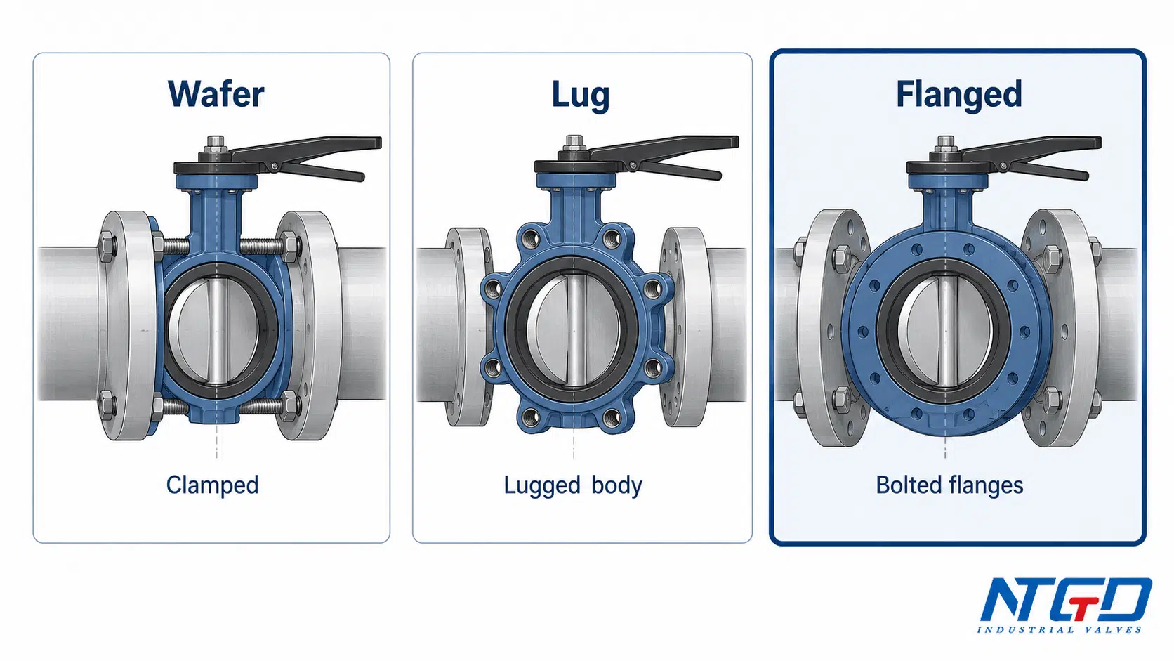
Quick Boundary: Wafer vs Lug vs Flanged Connections
| Connection type | General idea | Current page boundary |
|---|---|---|
| Wafer butterfly valve | Clamped between two pipe flanges | More compact, but not the focus of this page |
| Lug butterfly valve | Lugged body allows bolting from each side | Useful for certain piping layouts, but not the main topic here |
| Flanged butterfly valve | Valve body has flanged ends for bolted connection | Main focus of this page |
| Double flanged butterfly valve | More specific body configuration with full flanged ends | Should be handled by a dedicated double flanged page |
For a detailed wafer vs flanged selection comparison, use a dedicated comparison guide rather than expanding this page into a full connection-type comparison article.
Common Flanged Connection Problems and Troubleshooting
Most problems around flanged butterfly valves are not caused by the valve type alone. They often come from mismatch between valve, flange, gasket or liner, pipeline alignment, and service conditions.
| Mistake / condition | System-level consequence | Check first | Prevention / specification note |
|---|---|---|---|
| Wrong flange standard or drilling | Installation failure, uneven load, delayed commissioning | Drawing, flange standard, bolt-hole pattern | Confirm pipeline flange standard before ordering |
| Poor flange alignment | External leakage, high torque, reduced seat life | Parallelism, centering, pipe stress | Check alignment before tightening the connection |
| Pipe bore too small | Disc rubbing, high torque, disc edge damage | Disc swing clearance and pipe ID | Confirm disc clearance against pipeline bore |
| Over-tightening bolts | Seat or liner distortion, high torque, sealing instability | Seat condition, bolt load, flange face | Follow manufacturer tightening guidance and sequence |
| Debris or welding slag in pipeline | Seat damage and internal leakage | Pipeline cleanliness and seat surface | Flush or clean pipeline before operation |
| Incorrect gasket use | Leakage, over-compression, or liner damage | Valve design and manufacturer instruction | Do not assume gasket requirement without checking datasheet |
| Damaged or worn seat | Internal leakage across the valve | Seat / liner inspection | Select seat material according to media, temperature, and shutoff requirement |
| Loose flange bolts | External leakage at flange faces | Bolt condition and connection load | Recheck after startup if project procedure requires it |
| Wrong actuator sizing | Failure to open / close or unstable operation | Valve torque and actuator output | Size actuator with service pressure, seat design, and operating frequency |
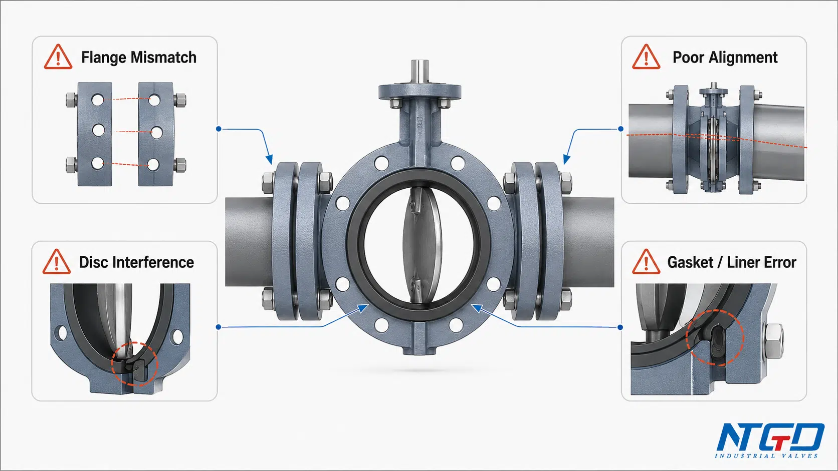
If leakage appears at the flanged connection, start by separating two questions: is the leakage external at the valve-pipe interface, or internal across the closed disc and seat? External leakage often points to flange face, gasket, liner, bolt load, or alignment issues. Internal leakage points more directly to the seat, disc edge, debris, or shutoff requirement.
Final Fit-Check Before Selecting a Flanged Butterfly Valve
Before confirming a flanged butterfly valve, review the selection as a system decision. The valve, pipe flanges, seat, disc, gasket or liner, actuator, and service conditions all need to work together.
| Check item | Confirmed? |
|---|---|
| Valve size and pipeline size | |
| Pressure class and project rating | |
| Flange standard and bolt-hole pattern | |
| Face-to-face dimension | |
| Body material | |
| Disc material | |
| Seat or liner material | |
| Media and temperature | |
| Shutoff or throttling duty | |
| Disc clearance and installation space | |
| Gasket / liner / flange sealing requirement | |
| Manual, gearbox, pneumatic, electric, or hydraulic operation | |
| Application risk: vibration, solids, corrosion, abrasion, or frequent cycling | |
| Required drawing, datasheet, or project specification |
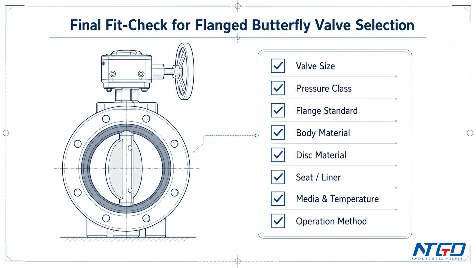
The key selection points are flange compatibility, seat or liner suitability, disc clearance, media and temperature, and operating method. If these are unclear, the RFQ should be reviewed before the valve is purchased.
FAQ About Flanged Butterfly Valves
What is a flanged butterfly valve?
A flanged butterfly valve is a quarter-turn butterfly valve with flanged ends on the valve body. It connects to matching pipe flanges using bolts, studs, and nuts. It is commonly used for industrial shutoff and some throttling services where a stable bolted connection is needed.
Is a flange type butterfly valve the same as a flanged butterfly valve?
In most industrial valve discussions, yes. “Flange type butterfly valve” usually means a butterfly valve identified by its flanged-end connection style. The exact body design, flange standard, pressure class, and seat design still need to be confirmed.
What does butterfly valve with flanges mean?
“Butterfly valve with flanges” is a natural way to describe a butterfly valve that has flanged connection ends. It usually refers to the same general product category as a flanged butterfly valve, but the buyer should still confirm whether the valve is single flanged, double flanged, or another flange-end design.
How does a butterfly valve flange connection work?
A butterfly valve flange connection works by bolting the valve body flanges to matching pipe flanges. The connection must match in size, flange standard, bolt-hole pattern, pressure class, and sealing design. The gasket, liner, or seat interface also needs to be checked according to the valve design.
Do flanged butterfly valves need gaskets?
It depends on the valve design. Some flanged butterfly valves use separate gaskets, while others rely on the seat or liner as part of the sealing interface. Do not assume the gasket requirement from the valve name alone. Confirm it with the valve manufacturer, datasheet, or project installation requirement before ordering or installation.
What is the difference between wafer and flanged butterfly valves?
A wafer butterfly valve is clamped between pipe flanges, while a flanged butterfly valve has flanged ends that connect directly to matching pipe flanges. The choice often depends on pressure, pipe size, installation space, maintenance access, rigidity, and total installed cost. A detailed comparison should be handled in a dedicated wafer vs flanged butterfly valve guide.
Is a double flanged butterfly valve the same as a flanged butterfly valve?
A double flanged butterfly valve is a more specific type of flanged butterfly valve. It usually refers to a valve body with full flanged ends on both sides. The broader term “flanged butterfly valve” may include several flange-end body configurations, so detailed double flanged specifications should be reviewed on a dedicated double flanged butterfly valve page.
When should you choose a flanged butterfly valve?
A flanged butterfly valve is often a good option when the piping system requires a stable bolted connection, larger pipe size support, industrial service compatibility, and easier integration with flange-based piping standards. It should be checked carefully when space is limited, pressure drop is critical, or the service contains abrasive solids.
Can a flanged butterfly valve be used for throttling?
Yes, it can be used for some throttling services, but not every throttling application. The pressure drop, flow velocity, seat material, disc position, vibration risk, and control accuracy should be reviewed. For severe control duty, a different valve type or a specialized design may be required.
What causes leakage at a flanged butterfly valve connection?
External leakage at the flanged connection may be caused by poor flange alignment, loose bolts, damaged flange faces, incorrect gasket use, liner distortion, or mismatch between valve and pipe flange standards. Internal leakage across the closed valve is more likely related to the seat, disc edge, debris, or shutoff requirement.
Conclusion
A flanged butterfly valve is not only a butterfly valve with flanged ends. It is a valve selection decision that combines body connection, flange standard, seat design, disc clearance, material compatibility, operating method, and service conditions.
Compared with compact wafer-style designs, flanged butterfly valves can provide a more stable bolted connection for many industrial piping systems. However, they also require careful checking of flange matching, installation space, gasket or liner design, pressure class, and actuator requirements.
Before selecting a flanged butterfly valve, confirm these key points:
- the flange standard and pressure class match the pipeline;
- the seat, liner, or gasket design is suitable for the media and temperature;
- the disc has proper clearance and will not interfere with the pipe bore;
- the operator or actuator matches the torque and operation frequency;
- the service conditions do not exceed the valve’s intended application range.
For project selection or RFQ review, prepare the valve size, flange standard, pressure class, media, temperature, body material, disc material, seat or liner requirement, and operation method. NTGD can review these details and help match the valve configuration to the actual service conditions.
