Nom de l'auteur : Bruce Zheng
Rôle de l'auteur : Cofondateur et ingénieur en vannes chez NTGD Valve
Bio de l'auteur : Bruce Zheng est cofondateur et ingénieur en vannes chez NTGD Valve, qui se concentre sur la sélection des vannes industrielles, les applications et le contenu technique pour les acheteurs B2B mondiaux.
Dernière mise à jour : 25 mai 2026
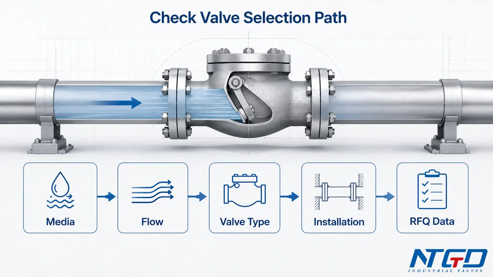
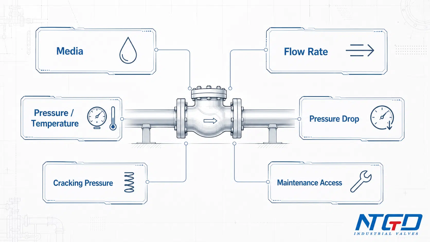
Le choix d'un clapet anti-retour ne se résume pas à l'adaptation au diamètre de la conduite. Un guide de sélection adéquat doit commencer par prendre en compte les conditions du système : fluide, débit, pression, température, sens d'installation, marge de perte de charge, ainsi que le risque de reflux ou de coup de bélier.
Dans les réseaux de tuyauterie industrielle, le choix d'un clapet anti-retour inadapté peut entraîner une perte de charge importante, un mouvement instable du disque, des vibrations, l'usure du siège, des fuites ou un claquement lors de l'arrêt de la pompe. Le clapet approprié est celui dont la conception du corps, le comportement à la fermeture, le matériau, le siège et l'orientation de montage correspondent au fonctionnement réel du système.
Ce guide explique comment choisir un clapet anti-retour en fonction du type de clapet, du sens d'écoulement, de la perte de charge, de la pression d'ouverture, de l'orientation de montage, de la réponse de fermeture et de l'adéquation à l'application. Il comprend également des tableaux de sélection et une liste de contrôle pour les appels d'offres, destinés à aider les ingénieurs et les acheteurs à établir des cahiers des charges plus précis avant de passer commande.
Réponse rapide : Comment choisir un clapet anti-retour
Pour choisir un clapet anti-retour, il convient tout d'abord de définir les conditions de fonctionnement, puis d'adapter le type de clapet au comportement du système. Le clapet doit s'ouvrir de manière fiable au débit normal, se fermer avant qu'un reflux susceptible de causer des dommages ne se produise, et éviter toute perte de charge excessive, tout cliquetis ou tout coup de bélier.
Voici une méthode pratique pour faire son choix :
| Étape | Ce qu'il faut vérifier | Pourquoi c'est important |
|---|---|---|
| 1 | Conditions relatives aux supports et aux services | La viscosité, la présence de matières solides, la corrosion, la vapeur, le gaz ou les fluides de type boue peuvent modifier le comportement de la vanne |
| 2 | Débit et pression | La vanne doit s'ouvrir à un débit normal et éviter toute perte de charge excessive. |
| 3 | Type de vanne | Les vannes à battant, à levier, à bille, à double plaque, à buse et à ressort se ferment différemment |
| 4 | Position d'installation | Le montage horizontal ou vertical influe sur le mouvement des disques, des billes, des pistons ou des ressorts |
| 5 | Détails des spécifications | Le matériau, le siège, la classe de pression, le raccord d'extrémité et les limites indiquées dans la fiche technique doivent correspondre au projet |
Le diamètre de la conduite doit confirmer le raccordement, et non déterminer le choix de la vanne. Si le débit réel est trop faible pour la vanne choisie, le disque ou l'élément de fermeture risque de rester partiellement ouvert, ce qui peut entraîner des cliquetis, des vibrations, l'usure du siège et une perte de charge inutile.
Pour en savoir plus sur les raisons pour lesquelles le dimensionnement des clapets anti-retour doit tenir compte de l'application et du débit plutôt que du seul diamètre de la conduite, consultez cet article Référence pour le dimensionnement des clapets anti-retour.
Commencez par tenir compte des conditions d'utilisation, et pas uniquement du diamètre des tuyaux
Le diamètre de la conduite n'est qu'un critère parmi d'autres. Une vanne de même diamètre nominal peut se comporter de manière très différente selon la vitesse d'écoulement, le mouvement du disque, la force du ressort, la conception du siège et la géométrie du corps.
Un clapet anti-retour choisi uniquement en fonction du diamètre de la conduite peut s'avérer trop grand par rapport au débit réel. En cas de faible débit, le disque peut ne pas atteindre une position stable en pleine ouverture. C'est dans cette position instable que se manifestent généralement le flottement, les vibrations, l'usure prématurée et les pertes de charge irrégulières.
Pour le choix d'un clapet anti-retour industriel, la première question à se poser est la suivante :
Quelle est la fonction que le système attend de la vanne dans des conditions réelles d'exploitation ?
Guide pratique en 5 étapes pour le choix d'un clapet anti-retour
Les cinq étapes décrites ci-dessus doivent être considérées comme une séquence décisionnelle et non comme des éléments distincts d'une liste de contrôle. Les fluides et les conditions d'écoulement définissent la plage de fonctionnement ; le type de vanne et son installation déterminent le mouvement de l'élément interne ; la perte de charge et la réponse à la fermeture déterminent si la vanne restera stable en service.
Un guide de sélection n'est utile que s'il établit un lien entre ces différents éléments. Une vanne dont la taille semble correcte peut tout de même ne pas passer le test d'ajustement si elle ne s'ouvre pas complètement, se ferme trop lentement, entraîne une perte de charge excessive ou ne peut pas être installée dans l'orientation requise.
Quand un tableau de sélection est utile… et quand il ne suffit pas
Un tableau de sélection des clapets anti-retour est utile pour une première sélection. Il permet de comparer les différents types de clapets en fonction de leur application, de leur tendance à la perte de charge, de leur temps de fermeture et des caractéristiques du fluide.
Toutefois, un tableau ne doit pas constituer le seul critère de sélection. Le choix définitif de la vanne doit encore s'appuyer sur les données du projet, les fiches techniques du fabricant, la confirmation de la classe de pression, l'examen de la compatibilité des matériaux et la vérification de l'installation.
Les critères à prendre en compte dans un guide de sélection des clapets anti-retour
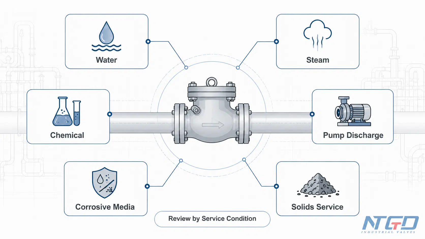
Un clapet anti-retour permet l'écoulement dans un seul sens et empêche le reflux lorsque les conditions de pression changent. Dans les conduites de refoulement des pompes, les canalisations de process, les réseaux d'eau, les circuits de vapeur et de condensat, les conduites de produits chimiques et d'autres applications industrielles, cette fonction anti-retour automatique protège les équipements et contribue à maintenir le sens d'écoulement du système.
Mais le terme “ clapet anti-retour ” est très général. Les différents modèles se ferment à des vitesses variables, génèrent des résistances à l'écoulement différentes et s'adaptent à des conditions de fluide variées.
Un bon guide de sélection devrait répondre aux questions suivantes :
- Quel type de vanne convient à cette application ?
- La vanne s'ouvrira-t-elle complètement au débit prévu ?
- Quelle perte de charge ou quelle perte de hauteur est acceptable ?
- Le système est-il sensible aux chocs hydrauliques ou aux coups de bélier ?
- La vanne peut-elle être installée dans le sens requis ?
- Le matériau est-il compatible avec le fluide et la température ?
- Quelles informations faut-il vérifier avant de lancer un appel d'offres ?
Le rôle d'un clapet anti-retour dans un système industriel
Dans les installations industrielles, un clapet anti-retour est généralement installé pour empêcher le reflux après l'arrêt d'une pompe, une fluctuation de pression ou une interruption du processus. Il peut servir à protéger les pompes, les compresseurs, les compteurs, les filtres, les échangeurs de chaleur, les réservoirs ou les équipements en amont.
Cette vanne ne régule pas le débit comme une vanne de régulation et ne doit pas être considérée comme un dispositif d'étranglement. Sa fonction principale est de s'ouvrir lorsque le débit dans le sens direct est suffisant et de se fermer lorsque le débit inverse commence ou lorsque la pression dans le sens direct descend en dessous du seuil de fermeture.
Clapet anti-retour vs soupape anti-retour : distinction terminologique
“Les termes ” clapet anti-retour “ et ” vanne anti-retour “ sont souvent utilisés pour désigner la même fonction générale : permettre l'écoulement dans un seul sens et empêcher le reflux. Sur certains marchés, l'abréviation ” NRV » est plus couramment employée dans les domaines des pompes, de l'eau ou des réseaux de canalisations en général.
Cet article est consacré au choix des clapets anti-retour. Une explication détaillée de la terminologie relative aux clapets anti-retour, des différents types de clapets anti-retour et des définitions de ces derniers doit figurer sur une page dédiée aux clapets anti-retour, et non dans ce guide de sélection.
Pour une explication plus détaillée de la terminologie, consultez le guide de NTGD consacré à Signification, principe de fonctionnement et types de vannes NRV industrielles.
Ce que ce guide ne remplace pas
Ce guide est destiné à la sélection technique initiale et à la préparation des appels d'offres. Il ne remplace pas :
- cahier des charges du projet ;
- fiches techniques des fabricants ;
- normes applicables ;
- calcul de la perte de charge ;
- analyse des pics de courant ;
- instructions d'installation ;
- analyse détaillée des besoins en ressources pour les systèmes critiques.
Pour les applications difficiles, les fluides dangereux, les systèmes à haute pression, à haute température ou sensibles aux coups de bélier, le choix final doit être vérifié par rapport au cahier des charges du projet et à la fiche technique de la vanne.
Types courants de clapets anti-retour dans le cadre de la sélection
Cette section n'a pas pour but de dresser un inventaire exhaustif des différents types de clapets anti-retour. L'objectif est de montrer comment les types de clapets anti-retour les plus courants influencent les choix lors de la sélection.
Les différents types de vannes se distinguent par leur perte de charge, leur vitesse de fermeture, leur sensibilité à l'installation, leur accessibilité pour l'entretien et leur tolérance aux particules solides ou à un débit instable.
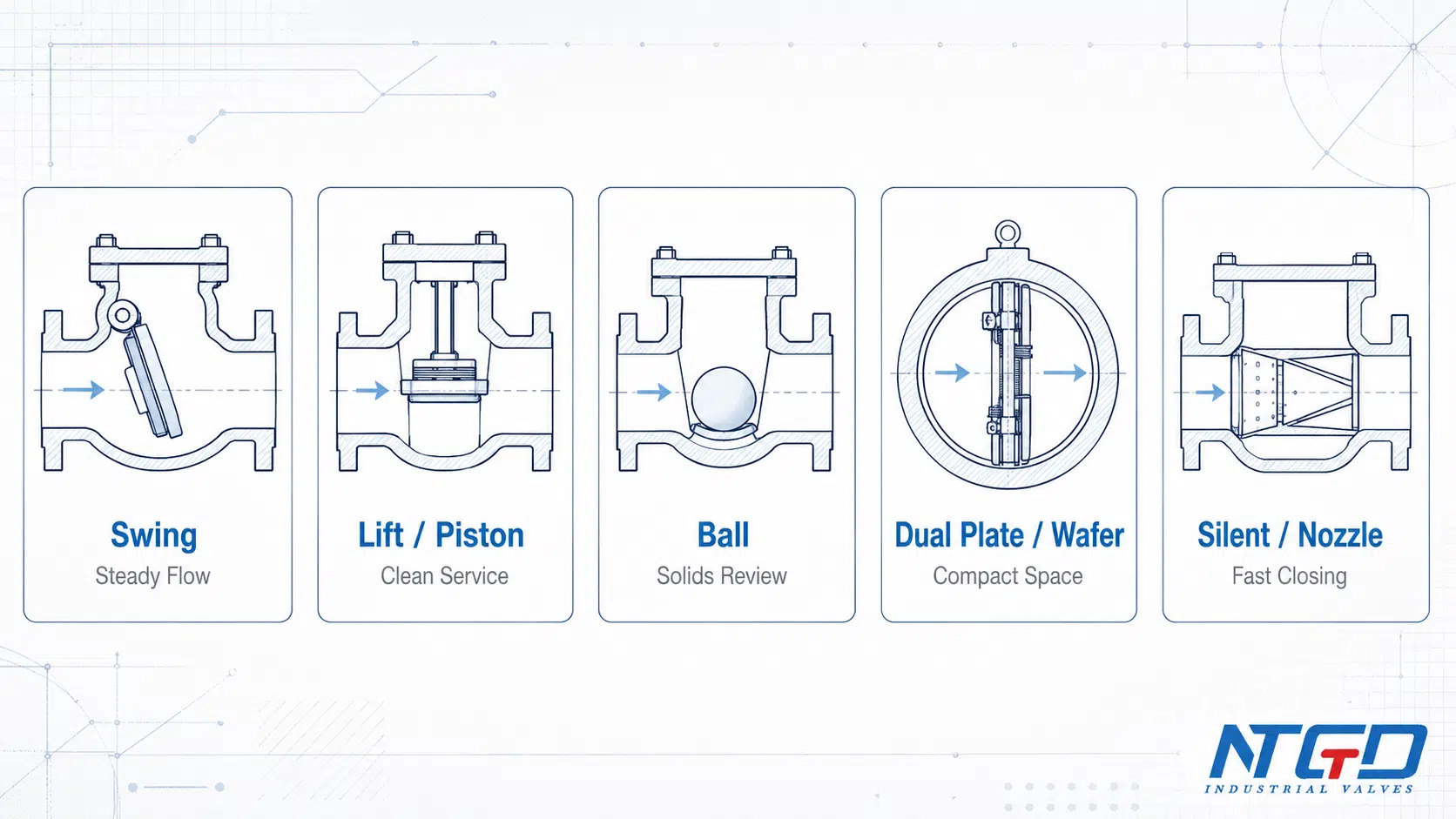
Clapets de non-retour à battant
Les clapets anti-retour à battant sont équipés d'un disque articulé qui s'ouvre lorsque le flux est dans le sens normal et se ferme lorsque le flux s'inverse. Ils sont souvent utilisés dans les canalisations de grand diamètre et dans des conditions de débit relativement constant.
Bien qu'elles puissent présenter une résistance à l'écoulement moindre lorsqu'elles sont entièrement ouvertes, la fermeture du disque peut s'avérer plus lente que celle des modèles à ressort. Dans les systèmes d'arrêt de pompe ou d'inversion rapide du sens d'écoulement, il convient d'évaluer les risques de claquement et de coup de bélier avant d'opter par défaut pour un clapet anti-retour à battant.
Lorsque le service préconise une conception à disque articulé, examinez le clapet anti-retour à battant détails après avoir vérifié la stabilité du flux, l'orientation et le risque de claquement.
Clapets anti-retour à levier et à piston
Les clapets anti-retour à levée et à piston utilisent un disque ou un piston guidé qui s'éloigne du siège lorsque le flux est dans le sens de l'avance. Ils sont souvent privilégiés pour les fluides propres et les applications à haute pression, où un mouvement guidé et une étanchéité plus stricte sont utiles.
Leur circuit interne peut entraîner une perte de charge plus importante que celle observée sur certains modèles à ouverture totale. Il convient de vérifier soigneusement l'orientation lors de l'installation ainsi que les conditions d'utilisation en milieu propre.
Pour les applications nécessitant un fonctionnement propre où le déplacement guidé du disque est privilégié, comparez les données techniques avec celles de NTGD. clapet anti-retour de levage limites de configuration et de la fiche technique.
Clapets anti-retour à bille
Les clapets anti-retour à bille utilisent une bille comme élément de fermeture. Selon leur conception, ils peuvent s'avérer utiles dans les applications liées aux eaux usées ou aux fluides contenant des matières solides, où l'on recherche une fermeture simple et une sensibilité réduite au colmatage.
Elles ne sont pas universelles. Les applications impliquant une pression élevée, des exigences de étanchéité précises, des températures élevées ou une orientation spécifique nécessitent un examen minutieux de la conception de la vanne et de sa fiche technique.
Clapets anti-retour à double plaque et à disque
Les clapets anti-retour à double plaque et à disque sont des modèles compacts souvent utilisés lorsque l'espace entre les faces est limité. Ils peuvent constituer une solution intéressante pour les réseaux de tuyauterie à brides nécessitant un corps de vanne plus court.
Le choix doit tenir compte du comportement des ressorts et des disques, de la vitesse d'écoulement, de la perte de charge et de la propreté du fluide. La présence de solides, de débris ou d'un écoulement très instable peut nuire aux performances.
Si le choix se résume essentiellement à une construction compacte à plaquettes ou à une conception à balancier plus volumineuse, le Comparaison entre un clapet anti-retour à disque et un clapet anti-retour à battant peut permettre d'affiner la sélection avant l'appel d'offres.
Buses, clapets anti-retour silencieux et à ressort
Les clapets anti-retour à buse, silencieux et à ressort sont souvent envisagés lorsqu'une fermeture rapide est nécessaire pour réduire le reflux et les coups de bélier. Ces modèles peuvent s'avérer utiles à proximité de la sortie d'une pompe ou dans des installations sensibles aux coups de bélier.
Leur choix doit néanmoins faire l'objet d'une sélection rigoureuse. Avant de faire ce choix, il convient d'examiner la force du ressort, la pression de rupture, la perte de charge, la sensibilité aux particules solides et l'accessibilité pour l'entretien.
Clapets anti-retour à disque basculant et à usage spécifique
Les modèles à disque basculant et autres conceptions spécialisées peuvent être choisis pour les grandes conduites, les objectifs de perte de charge réduite ou les exigences particulières en matière de réponse dynamique. Leur choix doit être évalué en fonction des données d'exploitation, du cahier des charges du projet et de la conception du fabricant.
Le choix des clapets anti-retour à usage spécifique ne doit pas se faire uniquement en fonction de leur nom. Le comportement réel à la fermeture, la perte de charge et les conditions d'installation sont plus importants que la désignation du produit.
Tableau comparatif : types de clapets anti-retour et applications correspondantes
| Type de soupape | Coupe classique | À surveiller | Tendance à la chute de pression | Réponse finale | Remarques relatives à l'installation | Implications de la sélection |
|---|---|---|---|---|---|---|
| Clapet anti-retour à battant | Grandes canalisations, débit constant, eau ou usage général | Vérifier le risque de coup de bélier lors de l'arrêt de la pompe ou dans les systèmes à reflux rapide ; contrôler l'usure des charnières | Souvent plus bas lorsqu'il est entièrement ouvert, selon le modèle | Plus lents que les modèles à ressort | Vérifier la compatibilité horizontale / verticale | Une bonne option de filtrage lorsque la faible résistance est importante, mais insuffisante pour les systèmes sensibles aux pics de tension |
| Clapet anti-retour à levée / à piston | Milieu propre, pression plus élevée, fermeture guidée | Résistance à l'écoulement plus élevée, exigence de service en milieu propre | Généralement plus hautes que les modèles à battant à ouverture totale | Fermeture guidée, en fonction de la conception | L'orientation peut être un sujet sensible | Utile lorsque le guidage des sièges prime sur la perte de charge minimale |
| Clapet anti-retour à bille | Eaux usées, certaines contenant des matières solides ou provenant de réseaux à faible hauteur de refoulement | Ne convient pas systématiquement aux conditions de haute pression, de haute température ou à toutes les orientations | Cela dépend de la trajectoire du corps et de celle de la balle | En fonction de la gravité / du débit | Vérifier si l'installation est adaptée à une orientation verticale ou horizontale | Vérifiez dans quels cas la tolérance aux débris est importante, mais assurez-vous également de vérifier l'étanchéité et les limites de pression |
| Clapet anti-retour à double plaque / disque | Tuyauterie à brides compacte, espace restreint | Usure des ressorts / disques, sensibilité aux corps solides | Moyen, en fonction de la conception | Plus rapide qu'un swing classique | Nécessite une vérification de la vitesse d'écoulement | Utile pour les configurations compactes, mais ne remplace pas l'analyse de la stabilité du flux |
| Buse / clapet anti-retour silencieux | Débit de la pompe, exigences en matière d'absence de coup de bélier, systèmes sensibles aux coups de bélier | Perte de charge, force du ressort, sensibilité aux particules solides | Moyen à élevé, selon le modèle | Fermeture rapide | Vérification de la fiche technique requise | Vérifier si la réponse à la clôture constitue un critère de sélection principal |
| Clapet anti-retour à disque basculant | Conduites de grand diamètre, analyse de la perte de charge réduite, applications spéciales | Coût, limites du service, accès pour la maintenance | Peut être plus faible dans certains modèles | Plus rapide que le mouvement oscillant standard dans certaines applications | Examen de la demande requis | Il convient de déterminer dans quels cas la perte de débit et la réponse dynamique doivent faire l'objet d'une analyse technique. |
Pour obtenir des informations complètes sur la conception, les dimensions, les caractéristiques de pression et de température, les options de raccordement et les limites spécifiques à chaque produit, veuillez consulter les ressources dédiées au type de vanne ou au produit concerné. Ce tableau est un outil d'aide à la sélection et ne constitue pas un tableau de spécifications techniques du produit.
Pour obtenir des informations complètes sur les détails de construction par type et les limites d'application, consultez la section dédiée Guide des types de clapets anti-retour plutôt que de transformer ce guide de sélection en une plateforme répertoriant tous les types.
Tableau des critères de sélection des clapets anti-retour
Une matrice de critères de sélection des clapets anti-retour permet de traduire des conditions générales du système en décisions concrètes. Le choix du clapet doit se fonder sur son comportement en service réel, et non pas uniquement sur son diamètre nominal ou sur la désignation générale de son type.
Compatibilité avec les fluides et les supports
Le fluide influe sur le choix du matériau, la compatibilité des joints, les propriétés d'étanchéité et le risque d'encrassement ou de collage.
L'eau, les eaux usées, la vapeur, les condensats, le gaz, l'huile, les fluides chimiques, les fluides visqueux et les applications contenant des solides peuvent chacun nécessiter des modèles de vannes différents. Les fluides corrosifs ou abrasifs exigent une attention particulière en ce qui concerne le matériau du corps, celui des composants internes, celui du siège, ainsi que l'accès pour la maintenance.
L'utilisation de matériaux incompatibles peut entraîner une corrosion accélérée, des fuites au niveau des sièges, le grippage des pièces internes ou un fonctionnement dangereux dans des applications chimiques ou impliquant des substances dangereuses.
Débit, vitesse d'écoulement et débit minimal
La vanne doit s'ouvrir suffisamment en conditions de débit normal. Si le débit est trop faible par rapport aux spécifications de la vanne, le disque, la bille ou le piston risque de ne pas atteindre une position ouverte stable. Cela peut entraîner des à-coups, des vibrations, du bruit ou de l'usure.
La vitesse d'écoulement influe également sur la perte de charge, la réponse de fermeture et le risque de coup de bélier lors de l'inversion du sens d'écoulement. Pour les systèmes critiques, les données de débit doivent être vérifiées par rapport à la fiche technique de la vanne plutôt que d'être estimées uniquement à partir du diamètre de la conduite.
Une vitesse d'écoulement insuffisante peut maintenir l'élément de fermeture dans une position partiellement ouverte, ce qui entraîne des vibrations, une chute de pression instable et une usure prématurée du siège.
Pression de service, température et classe de pression
La classe de pression de la vanne doit correspondre à la pression nominale et à la pression de service du système. La température influe également sur le choix des matériaux, celui du siège, le comportement du ressort et les propriétés du fluide.
En cas d'utilisation à haute température, en milieu cryogénique, en présence de vapeur ou dans un milieu corrosif, le matériau et le siège doivent être vérifiés par rapport au cahier des charges du projet et à la fiche technique. Le fait que la classe de pression du corps soit correcte ne garantit pas automatiquement que le matériau du siège, du ressort, du joint ou des pièces internes soit adapté à la température de service et au fluide concerné.
Compatibilité des matériaux, des sièges et des joints
Les matériaux du corps, du disque, du ressort, du siège et du joint doivent être adaptés au fluide et à la température. Il peut arriver qu’un corps de vanne soit adapté à la pression, mais que le siège ou les composants internes ne soient pas adaptés au fluide.
Les sièges souples peuvent contribuer à l'étanchéité dans certaines applications, mais il convient de vérifier la température, la compatibilité chimique et la résistance à l'usure. Les sièges métalliques peuvent mieux supporter des températures élevées ou des conditions d'utilisation abrasives dans certaines conceptions, mais il convient de vérifier les performances d'étanchéité attendues.
Si le siège ou le joint n'est pas compatible avec le fluide, la vanne peut présenter des fuites même si le matériau du corps semble adapté.
Pour les applications soumises à la corrosion, utilisez le clapet anti-retour en acier inoxydable page à consulter comme référence au niveau du produit après avoir vérifié la composition chimique du support et la température.
Pression de fissuration et conditions d'ouverture
La pression d'ouverture est la pression minimale en amont nécessaire pour que le clapet anti-retour commence à s'ouvrir. Elle revêt une importance particulière pour les clapets anti-retour à ressort, les petits clapets anti-retour et les systèmes à basse pression.
Si la pression d'ouverture est trop élevée, la vanne risque de ne pas s'ouvrir correctement à faible débit. Si elle est trop faible par rapport au comportement du système, la vanne peut devenir instable ou ne pas fournir la réponse escomptée. Les exigences précises dépendent de la conception de la vanne et des conditions d'utilisation.
Si la pression de déclenchement ne correspond pas à la pression différentielle disponible, la vanne risque de ne pas s'ouvrir à un débit normal ou de fonctionner de manière instable à proximité du point d'ouverture.
Considérations relatives à l'accès pour la maintenance et au cycle de vie
Un faible coût initial ne garantit pas toujours un meilleur choix. Il convient d'examiner les aspects liés à l'accès pour la maintenance, à l'usure des sièges, au risque d'encrassement, à la disponibilité des pièces de rechange et au risque de temps d'arrêt avant de choisir définitivement le type de vanne.
Dans le cas de conduites enterrées, d'emplacements en hauteur, de fluides dangereux ou de systèmes fonctionnant en continu, la facilité d'entretien peut s'avérer aussi importante que le choix initial du type de vanne.
Un accès difficile pour l'entretien peut transformer un problème mineur au niveau d'un siège ou d'une charnière en un temps d'arrêt prolongé et en un risque accru tout au long du cycle de vie.
Tableau des critères de sélection des clapets anti-retour
| Critère | Pourquoi c'est important | Ce qu'il faut confirmer | Risque en cas de négligence | Direction de la sélection |
|---|---|---|---|---|
| Type de média | Permet de déterminer le matériau, l'emplacement et le risque d'encrassement | Eau, vapeur, gaz, produits chimiques, fluides de type boue, fluides visqueux ou contenant des solides | Corrosion, grippage, endommagement des sièges, fuites, fonctionnement dangereux | Choisissez une carrosserie, des finitions et un siège compatibles |
| Débit | Détermine si la vanne s'ouvre complètement | Débit normal, débit minimal, débit intermittent | Ouverture partielle, broutage, vibrations, usure | Déterminez le dimensionnement en fonction des conditions d'écoulement, et non pas uniquement en fonction du diamètre de la conduite |
| Pression et température | A une incidence sur la classe de pression et les limites des matériaux | Pression de service, pression nominale, plage de température | Incompatibilité entre le corps, le siège, le ressort ou le joint | Vérifier la classe de pression et les limites de température |
| Perte de charge / perte de hauteur | Cela a une incidence sur les pertes d'énergie et les performances du système | Perte de charge admissible, Cv / Kv, résistance à l'écoulement | Pertes d'énergie élevées, débit limité, fonctionnement instable | Comparer la conception des vannes et le tracé du circuit d'écoulement |
| Pression de fissuration | Influence le comportement à l'ouverture | Pression d'ouverture requise et condition de faible débit | Impossibilité d'ouverture, fonctionnement instable à l'approche du point d'ouverture | Vérifier les données relatives à l'ouverture des ressorts ou des disques |
| Réponse finale | Influence le reflux et les claquements | Arrêt de la pompe, risque de coup de bélier, vitesse de reflux | Coup de bélier, bruit, contraintes sur les canalisations | Envisagez un modèle sans claquement ou à fermeture rapide |
| Orientation de l'installation | Affecte les pièces mobiles internes | Horizontal, vertical vers le haut, vertical vers le bas | Ouverture incomplète, blocage, fermeture défaillante | Vérifier l'orientation autorisée |
| Matériau et siège | A une incidence sur la corrosion, les fuites et l'usure | Matériaux du corps, du disque, du ressort, du siège et du joint | Fuites, corrosion, durée de vie réduite | Adapter le matériau au support et à la température |
| Accès pour l'entretien | A un impact sur le coût du cycle de vie et les temps d'arrêt | Espace d'accès, couvercle amovible, besoins en matière d'inspection | Temps d'arrêt plus longs, réparations plus complexes, risques accrus tout au long du cycle de vie | Pensez dès le départ à la facilité d'entretien |
Ces critères sont interdépendants. Une vanne peut satisfaire aux critères relatifs au matériau mais échouer au test de perte de charge ; une autre peut présenter une faible résistance mais se fermer trop lentement pour une conduite de pompe sensible aux coups de bélier. La vérification finale de l'adéquation doit comparer tous les critères essentiels avant de valider le choix du type de vanne.
Débit, perte de charge et hauteur de perte
La perte de charge est l'un des facteurs les plus importants à prendre en compte lors du choix d'un clapet anti-retour. Un clapet anti-retour n'est pas simplement un dispositif de fermeture et d'ouverture. Il fait partie intégrante de la résistance de la tuyauterie, et sa géométrie interne peut influer sur l'efficacité du débit.
Pourquoi le dimensionnement des clapets anti-retour doit-il tenir compte des conditions de débit ?
Il convient de choisir un clapet anti-retour en fonction des conditions réelles de débit. Le diamètre nominal de la conduite ne suffit pas à lui seul à garantir que l'élément interne s'ouvrira complètement ou fonctionnera de manière stable.
Si une vanne est surdimensionnée par rapport au débit réel, le clapet peut rester en position partiellement ouverte. Cela peut entraîner des vibrations, des cliquetis, une usure du siège et une chute de pression instable. Si une vanne est trop restrictive, elle peut augmenter la perte de charge et réduire le rendement du système.
Un bilan pratique devrait inclure :
- débit normal ;
- débit minimal ;
- débit maximal ;
- comportement au démarrage et à l'arrêt ;
- courbe de débit de la pompe ou plage de fonctionnement du système, le cas échéant ;
- perte de charge admissible.
Comment la perte de charge influe sur les performances du système
La perte de charge au niveau d'un clapet anti-retour peut avoir une incidence sur le choix de la pompe, la consommation d'énergie, le débit fourni et la stabilité du système. Dans certains systèmes, une légère augmentation de la perte de charge peut être acceptable. Dans d'autres, elle peut nuire aux performances du processus ou augmenter les coûts d'exploitation.
La forme du corps de la vanne, la position du disque, la force du ressort, la restriction de passage et le tracé interne du flux ont tous une incidence sur la perte de charge. C'est pourquoi deux clapets anti-retour de même diamètre nominal et de même classe de pression peuvent présenter des performances différentes.
L'analyse de la perte de charge doit être effectuée en fonction du point de fonctionnement réel. Une vanne qui semble convenir à un certain débit peut entraîner une perte de charge excessive ou un fonctionnement instable à un autre débit.
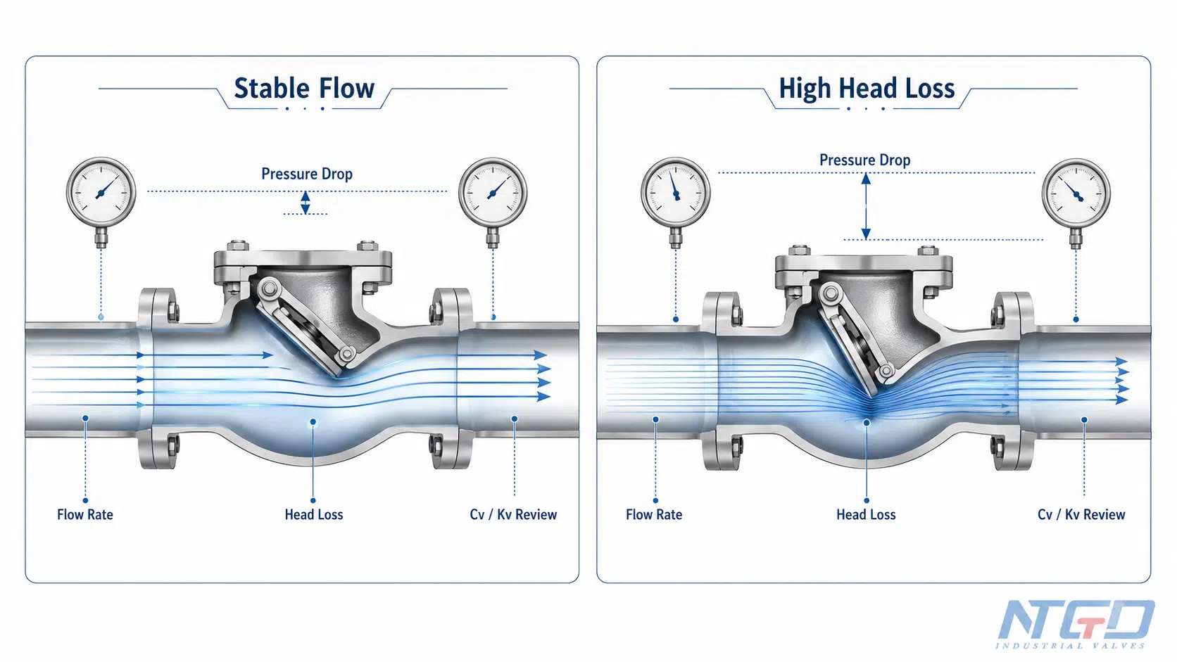
Cv / Kv, perte de charge et résistance à l'écoulement dans le cadre d'une sélection pratique
Cv et Kv sont des coefficients de débit utilisés pour comparer le débit qu'une vanne peut laisser passer sous une différence de pression donnée. Ils sont utiles pour comparer différents modèles de vannes, mais doivent être interprétés à la lumière de la fiche technique du fabricant et des conditions réelles d'utilisation.
Pour connaître la relation générale entre Cv / Kv, le débit et la perte de charge, consultez ce document Référence sur les coefficients de débit Cv et Kv.
Pour faciliter le choix :
- un coefficient de débit plus élevé indique généralement une résistance plus faible, mais uniquement dans les conditions d'essai ou de conception spécifiées ;
- une conception à faible perte de charge peut néanmoins s'avérer inadaptée si la fermeture est trop lente ;
- un système à fermeture rapide peut réduire le risque de claquement, mais peut présenter un comportement différent en matière de perte de charge ;
- La teneur en solides, la viscosité et l'ouverture partielle peuvent modifier les performances réelles.
Lors de la comparaison des valeurs Cv ou Kv, il convient de se baser sur le débit et la différence de pression réels en service, et non uniquement sur le diamètre nominal de la conduite. Les vannes surdimensionnées peuvent fonctionner en ouverture partielle, ce qui peut entraîner une perte de charge effective et une usure plus importantes que ne le laisse supposer la comparaison figurant dans le catalogue.
Une faible perte de charge ne signifie pas nécessairement que c'est le meilleur choix
Un clapet à faible perte de charge n'est pas toujours le meilleur clapet anti-retour. Si le système présente un risque d'inversion rapide du débit, d'arrêt de la pompe ou de coup de bélier, la rapidité de fermeture peut s'avérer plus importante que la résistance minimale.
La sélection doit respecter un équilibre entre :
- chute de pression ;
- vitesse de fermeture ;
- compatibilité avec les médias ;
- l'orientation de l'installation ;
- l'accès à la maintenance ;
- cahier des charges du projet.
Il existe souvent un compromis entre une faible perte de charge et une réponse de fermeture rapide. Une conception visant à minimiser la résistance peut ne pas permettre une fermeture suffisamment rapide pour un système sensible aux coups de bélier, tandis qu'une conception à fermeture rapide peut nécessiter un examen plus approfondi de la perte de charge, de la force du ressort et du débit minimal.
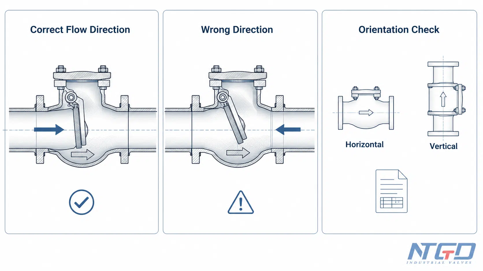
Sens d'écoulement, flèche indiquant le sens d'écoulement et orientation lors de l'installation
Un clapet anti-retour doit être installé dans le sens correct du débit. Si le clapet est installé à l'envers, il risque de bloquer le débit, de ne pas assurer la protection du système ou de provoquer des conditions de pression anormales.
Pourquoi le sens d'écoulement est-il important pour le choix d'un clapet anti-retour ?
La plupart des clapets anti-retour comportent une flèche ou un repère sur le corps indiquant le sens de circulation prévu. Le clapet doit être installé de manière à ce que le flux dans le sens normal suive ce repère.
Le sens d'écoulement influe également sur le mouvement de l'élément interne. Un disque pivotant, un disque de levage, un piston, une bille ou un élément à ressort peut fonctionner sous l'effet de la gravité, de la force d'écoulement, de la force d'un ressort ou d'un mouvement guidé. Un sens d'écoulement inadapté peut empêcher l'ouverture et la fermeture normales.
Installation horizontale ou verticale
Toutes les clapets anti-retour ne conviennent pas à toutes les orientations. Certains clapets peuvent fonctionner dans des conduites horizontales, d'autres dans des conduites verticales à écoulement ascendant, tandis que d'autres encore peuvent présenter des restrictions pour un écoulement vertical descendant.
Il convient de vérifier l'orientation de l'installation avant de procéder au choix, en particulier pour :
- clapets anti-retour à battant ;
- clapets anti-retour à levier et à piston ;
- clapets anti-retour à bille ;
- clapets anti-retour à double plaque ou à disque ;
- clapets anti-retour à ressort ou silencieux.
Un écoulement vertical vers le bas nécessite une prudence particulière et une vérification de la fiche technique, car la gravité et le mouvement de l'élément de fermeture peuvent affecter l'ouverture, la mise en place et la fermeture complète. Ne partez pas du principe qu'une installation verticale est acceptable, sauf si la conception de la vanne le permet.
Sortie de pompe, coudes et zones d'écoulement instable
Les clapets anti-retour fonctionnent souvent à proximité de pompes, de coudes, de réducteurs, de tés ou d'autres sources de débit instable. La turbulence peut affecter le mouvement du disque et son comportement à la fermeture.
Si la vanne est installée trop près d'une zone de turbulence, elle peut présenter des vibrations, une ouverture incomplète, du bruit, une usure prématurée ou une fermeture instable. Son emplacement exact doit être vérifié par rapport au schéma de tuyauterie du projet, aux instructions du fabricant et aux spécifications applicables.
Lorsque les conditions d'installation nécessitent une confirmation figurant dans la fiche technique
La vérification de la fiche technique revêt une importance particulière dans les cas suivants :
- la vanne sera installée à la verticale ;
- la vanne se trouve près de la sortie de la pompe ;
- le système subit des démarrages et des arrêts fréquents ;
- le milieu contient des solides ;
- la vanne doit permettre de maîtriser les risques de coup de bélier ;
- l'accès pour la maintenance est restreint ;
- Les limites de perte de charge sont strictes.
Exigences relatives à la fermeture, au coup de bélier et à l'absence de claquement
Un clapet anti-retour doit se fermer au bon moment. S'il se ferme trop tard, un reflux peut se produire avant la fermeture complète. S'il se ferme trop brusquement dans de mauvaises conditions, le système peut subir une surpression ou un coup de bélier.
Pourquoi la vitesse de fermeture d'un clapet anti-retour est-elle importante ?
La vitesse de fermeture influe sur le reflux, le bruit, l'impact sur le siège et les contraintes exercées sur la tuyauterie. Une vanne à fermeture lente peut laisser passer davantage de reflux avant que le disque n'atteigne le siège. Une vanne à fermeture rapide peut réduire le reflux, mais son adéquation dépend tout de même de la pression du système, de la vitesse d'écoulement, du fluide et de la conception de la vanne.
L'objectif n'est pas simplement de choisir la vanne la plus rapide. L'objectif est d'adapter le comportement de fermeture à la dynamique du système.
Risques liés aux coups de bélier, aux reflux et aux coups de marteau
Un coup de bélier peut se produire lorsque le reflux force le clapet anti-retour à se fermer brusquement. Cela peut entraîner du bruit, des vibrations, un pic de pression et des contraintes sur le clapet et la tuyauterie.
Les installations comportant un arrêt de pompe, une vitesse d'écoulement élevée, de longues canalisations, des inversions rapides ou un débit instable doivent faire l'objet d'une évaluation afin de déterminer le risque de coup de bélier. Dans ces cas, le type de vanne et la vitesse de fermeture constituent des critères de sélection essentiels.
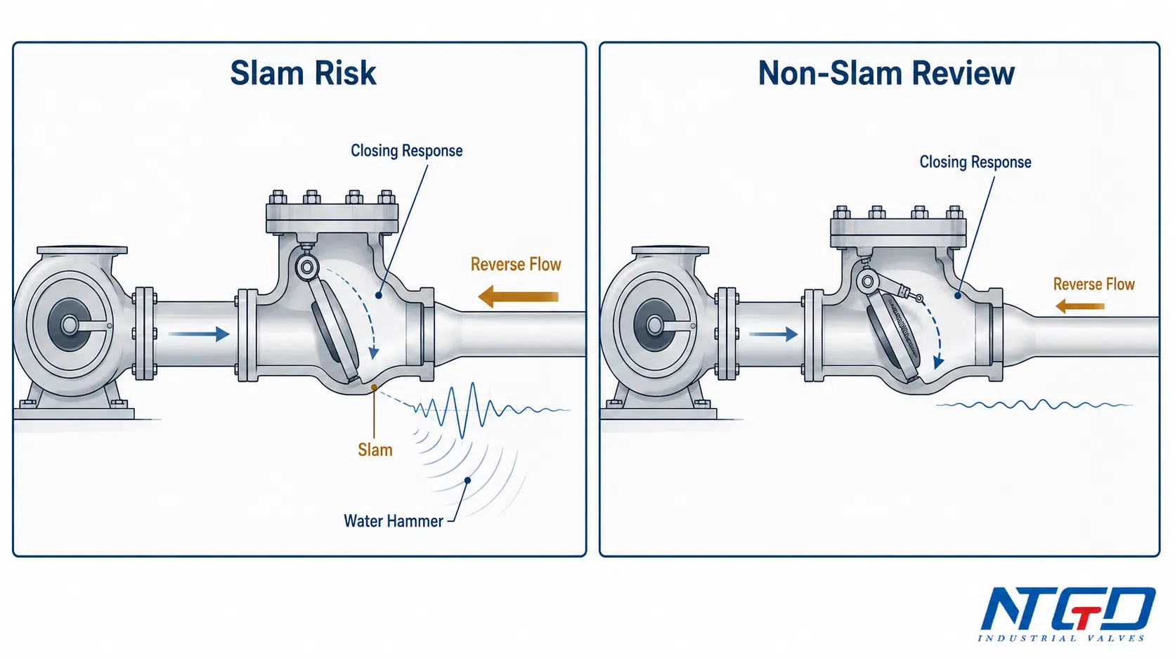
Quand envisager l'utilisation de clapets anti-retour à ressort, silencieux ou à buse ?
On peut envisager l'utilisation de clapets anti-retour à ressort, silencieux ou à buse lorsque le système nécessite une fermeture plus rapide ou qu'il faut réduire le risque de claquement. Ces modèles peuvent s'avérer utiles à proximité de la sortie d'une pompe ou dans des systèmes où il est nécessaire de minimiser rapidement le reflux.
Cependant, il ne faut pas les choisir uniquement parce que l’expression “ sans claquement ” semble plus sûre. L’ingénieur doit également vérifier :
- pression de fissuration ;
- chute de pression ;
- matériau du ressort ;
- débit ;
- la propreté des médias ;
- sensibilité aux solides ;
- l'orientation de l'installation ;
- l'accès à la maintenance.
Le présent guide de sélection ne présente les clapets anti-retour à ressort, silencieux et à buse que comme options de réponse à la fermeture. Pour obtenir des informations détaillées sur la conception, les caractéristiques des ressorts, les plages de pression d'ouverture et les limites spécifiques à chaque produit, il convient de consulter les ressources dédiées à chaque produit ou à chaque thème.
Pour des limites de sélection « non-slam » plus profondes, consultez le document de NTGD intitulé guide de clapet anti-retour à ressort une fois que la pression de rupture du système, la perte de charge et le degré de propreté du fluide sont connus.
Le lien entre la pression de fissuration et le comportement à la fermeture et à l'ouverture
La pression de fissuration n'est pas seulement un détail propre aux petites vannes. Elle détermine si la vanne peut s'ouvrir sous l'effet de la pression en amont disponible.
Dans les systèmes à basse pression, une pression de déverrouillage élevée peut empêcher une ouverture correcte. Dans les systèmes nécessitant une réponse de fermeture spécifique, la force du ressort et la pression de déverrouillage peuvent influencer à la fois le comportement à l'ouverture et à la fermeture.
Pour les clapets anti-retour à ressort ou silencieux, la pression d'ouverture doit être vérifiée dans la fiche technique et adaptée aux conditions réelles de débit et de pression.
Tableau de sélection des clapets anti-retour en fonction de l'application
Un tableau de sélection des clapets anti-retour est particulièrement utile lorsqu'il aide les utilisateurs à affiner leurs choix avant de consulter les fiches techniques. Il ne doit pas être considéré comme une décision de conception définitive.
Comment utiliser ce tableau de sélection des clapets anti-retour
Utilisez le tableau ci-dessous comme outil de présélection. Il indique les sens d'ouverture des vannes couramment pris en compte pour différentes conditions d'utilisation. Le choix final dépend toutefois du débit, de la perte de charge, de l'orientation de l'installation, des matériaux, de la conception du siège et des spécifications du projet.
Utilisez ce tableau uniquement à des fins de présélection. Il ne doit pas constituer le seul critère de sélection pour les applications difficiles, les fluides dangereux ou toxiques, les applications cryogéniques ou à haute température, ni pour les systèmes présentant des antécédents connus de coups de bélier.
Conditions d'utilisation qui déterminent généralement le choix de la vanne
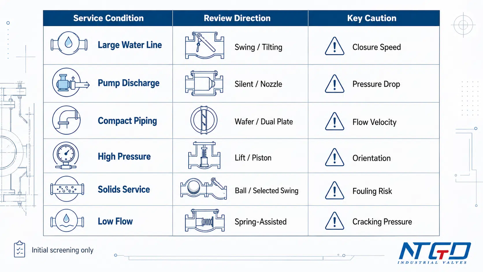
| Conditions de service | Direction commune des vannes | Préoccupation liée à la perte de charge | Problème de coup de bélier / de choc hydraulique | Médias / Problématique des matières solides | Note de sélection |
|---|---|---|---|---|---|
| Grande conduite d'eau horizontale | Clapet anti-retour à disque basculant ou pivotant | Généralement évalué pour une faible perte de charge | Vérifier si l'arrêt ou l'inversion de la pompe est rapide | Milieux généralement propres à modérément propres | Vérifier la vitesse de fermeture et l'orientation de montage |
| Débit de la pompe présentant un risque de coup de bélier | Clapet anti-retour silencieux, à buse ou à ressort | Comparer la perte de charge par rapport au point de fonctionnement de la pompe | Haute priorité | Des supports propres sont préférables pour certaines conceptions | Examinez ensemble la vitesse de fermeture, la pression de rupture et la perte de charge admissible |
| Tuyauterie compacte à brides | Clapet anti-retour à double plaque ou à disque | Moyen, en fonction de la conception | Moyenne à élevée selon le système | Les aliments solides peuvent affecter le mouvement des disques | Vérifier la vitesse d'écoulement et la compatibilité du ressort et du disque |
| Service de nettoyage à haute pression | Clapet anti-retour à levier ou à piston | Souvent plus élevées que celles des modèles à balancier | Dépendant de la conception | Préférence pour les supports propres | Vérifier l'orientation et la classe de pression |
| Service de traitement des eaux usées ou des matières solides | Clapet anti-retour à bille ou modèles à battant sélectionnés | Cela dépend du parcours des matières fédées et des matières solides | Analyse des fautes de « slam » et de « fouling » | Haute priorité | Vérifier la taille des particules solides, la conception du siège et l'accès pour l'entretien |
| Circuit de vapeur ou de condensat | Clapet à levée, à piston, à battant ou spécial, selon les conditions | À examiner attentivement | Cela dépend de l'inversion du flux et du comportement des condensats | La propreté et la température sont importantes | Vérifier les limites relatives au matériau, à l'emplacement et à la température |
| Service chimique corrosif | Conception d'un clapet anti-retour compatible avec les matériaux | Cela dépend du type sélectionné | Spécifique à l'application | Problème majeur de compatibilité | Vérifier les matériaux de la carrosserie, des garnitures, des sièges et des joints |
| Service à faible débit ou intermittent | Conception à ressort ou guidée, adaptée aux dimensions | Éviter le fonctionnement en ouverture partielle | Moyen | Cela dépend du support | Vérifier le débit minimal, la pression de fissuration et la stabilité du comportement d'ouverture |
Quand le graphique doit-il déclencher une revue technique ?
Un tableau de sélection doit donner lieu à un examen plus approfondi lorsque :
- le système est caractérisé par des démarrages et des arrêts fréquents de la pompe ;
- un coup de bélier s'est déjà produit ;
- les limites de perte de charge sont strictes ;
- la vanne est installée à la verticale ;
- le fluide contient des solides ou un liquide visqueux ;
- le fluide est corrosif, dangereux, à haute température ou à haute pression ;
- la vanne se trouve à proximité de la sortie de la pompe, de coudes, de réducteurs ou de tés ;
- L'accès pour la maintenance est restreint.
Risques courants liés à un mauvais choix
Un clapet anti-retour peut sembler simple, mais un mauvais choix peut entraîner de réels problèmes de fonctionnement. Les erreurs les plus courantes consistent à se baser uniquement sur le diamètre de la conduite, à ne pas tenir compte de la vitesse d'écoulement, à négliger l'orientation lors de l'installation et à choisir un type de clapet sans prendre en considération son comportement à la fermeture.
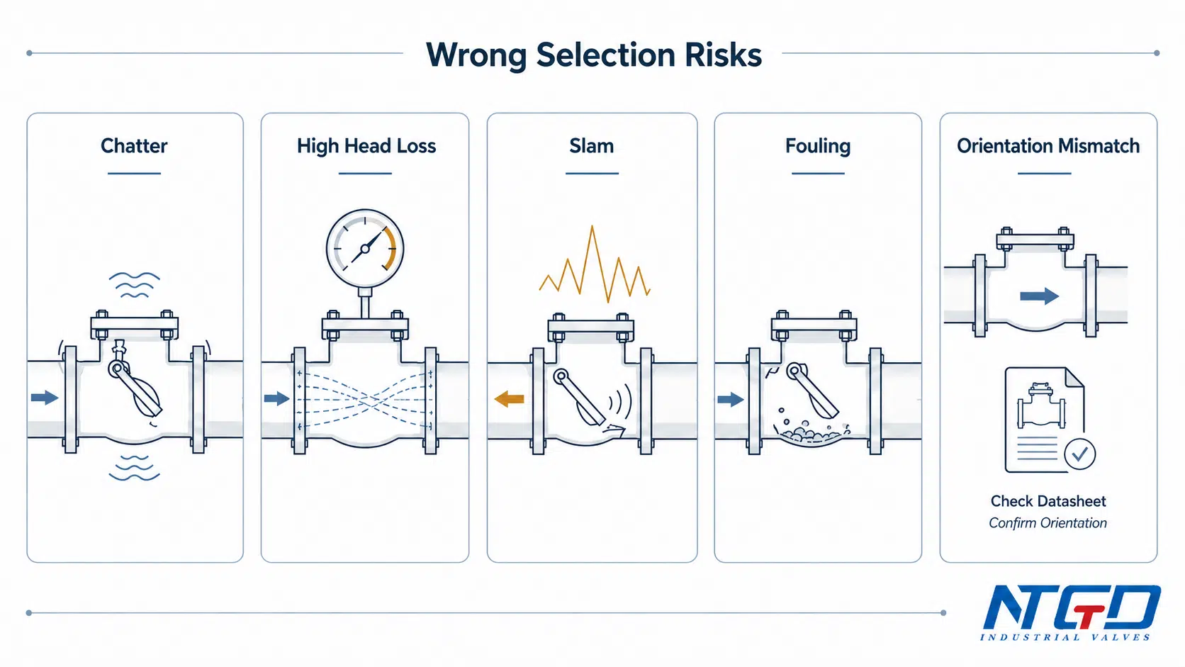
Chute de pression élevée ou perte d'énergie
Une conception restrictive de la vanne peut accroître la perte de charge. Cela peut entraîner une diminution du débit, une augmentation de la charge de la pompe ou une baisse du rendement du système. Il convient d'évaluer la perte de charge avant de procéder au choix définitif, en particulier dans les systèmes fonctionnant en continu.
Vibrations, battements ou ouverture incomplète
Si la vanne ne s'ouvre pas complètement dans des conditions de débit normales, l'élément interne peut entrer en flottement. Cela peut entraîner du bruit, des vibrations, l'usure du siège et une chute de pression instable.
Ce phénomène est souvent lié à des vannes surdimensionnées, à un faible débit, à un débit instable ou à une mauvaise adéquation entre la conception de la vanne et les conditions d'utilisation.
Coup de bélier et coup de marteau
Si un reflux se produit avant la fermeture de la vanne, le disque ou l'élément de fermeture peut heurter violemment le siège. Cela peut entraîner un pic de pression, du bruit, des vibrations et des contraintes sur la tuyauterie.
Pour les installations comportant de longues conduites, des débits élevés, des arrêts de pompe ou des inversions rapides du sens d'écoulement, il convient d'envisager des solutions anti-claquement ou à fermeture rapide.
Encrassement, obstruction par des matières solides ou grippage
Les particules solides, les débris, le tartre, les fluides visqueux ou les fluides encrassés peuvent entraver le mouvement du disque, du piston, du ressort ou de la bille. Une vanne qui fonctionne correctement dans de l'eau propre peut présenter des défaillances lorsqu'elle est utilisée avec des fluides encrassés.
La propreté des supports doit faire partie intégrante des critères de sélection, et non être un élément secondaire.
Fuites, usure des sièges et problèmes d'entretien
Un matériau inadapté, une compatibilité insuffisante avec le siège, un mouvement instable ou des fluides abrasifs peuvent entraîner des fuites et des problèmes d'entretien.
Il convient de réfléchir dès le départ à l'accès pour la maintenance. Une vanne difficile à inspecter ou à entretenir peut allonger les temps d'arrêt, même si son coût d'achat initial est moins élevé.
Matrice des risques liés à une mauvaise sélection
| Mauvaise sélection | Résultat possible | Une cause commune | Comment réduire les risques |
|---|---|---|---|
| Sélection en fonction du diamètre des tuyaux uniquement | Vibrations, ouverture partielle, débit instable | Débit trop faible par rapport à la taille de la vanne | Vérifier le débit normal et le débit minimal |
| Ne pas tenir compte de la perte de charge | Perte d'énergie, débit réduit | Géométrie interne à haute résistance | Comparer les données relatives aux valeurs Cv et Kv ainsi qu’aux pertes de charge |
| Ignorer la réponse de clôture | Coup de bélier, coup de marteau, bruit | Fermeture lente dans un système à inversion rapide | Examiner les modèles sans claquement ou à fermeture rapide |
| Ne pas tenir compte de l'état du support | Encrassement, grippage, fuite | Solides, fluides visqueux, corrosion | Choisir le type et le matériau de la vanne en fonction du fluide |
| Ne pas tenir compte de l'orientation lors de l'installation | Problème d'ouverture ou de fermeture | Vanne non adaptée à une installation verticale ou horizontale | Vérifier les limites d'orientation indiquées dans la fiche technique |
| Sans tenir compte de la pression de fissuration | La vanne ne s'ouvre pas à basse pression | La force du ressort est trop élevée pour le système | Vérifier la pression de fissuration à l'aide des données techniques |
| Ignorer l'accès à la maintenance | Augmentation des temps d'arrêt | Vanne difficile à inspecter ou à entretenir | Vérifiez dès que possible les conditions d'accès et de service |
Liste de contrôle finale des demandes de devis et des fiches techniques avant de passer commande
Un bon appel d'offres ne doit pas se contenter de demander “ un clapet anti-retour ”. Il doit inclure suffisamment de données sur le système pour permettre au fournisseur ou à l'ingénieur chargé des clapets de vérifier que la conception est correcte.
Des informations incomplètes ou inexactes dans l'appel d'offres constituent une cause fréquente de mauvais choix de clapet anti-retour. L'absence de données relatives au débit, au fluide, à l'orientation ou aux limites de perte de charge peut conduire au choix d'un clapet qui, bien qu'adapté au raccordement de la conduite, ne répondra pas aux exigences réelles d'exploitation.
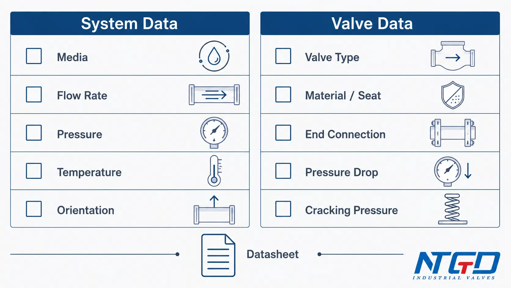
Données du système à vérifier avant de choisir un clapet anti-retour
Avant la sélection finale, confirmez :
- nom et état du support ;
- que le fluide soit propre, corrosif, visqueux, abrasif ou contenant des particules solides ;
- débit normal ;
- débit minimal et maximal ;
- pression de fonctionnement ;
- pression de conception ;
- température de fonctionnement ;
- l'orientation de l'installation ;
- le sens de l'écoulement ;
- fréquence de démarrage/arrêt de la pompe ;
- risque de coup de bélier ou de surtension ;
- perte de charge admissible ;
- l'accès à la maintenance.
Informations relatives aux vannes à vérifier avant l'appel d'offres
La fiche technique de la vanne doit indiquer :
- type de vanne ;
- dimension / NPS / DN ;
- classe de pression ;
- matériau du corps ;
- matériau des garnitures / disques / ressorts ;
- le matériau du siège et du joint ;
- connexion finale ;
- en présentiel ou dans un espace d'installation ;
- pression de fissuration, le cas échéant ;
- les données relatives au coefficient de débit ou à la perte de charge, le cas échéant ;
- normes applicables ou exigences du projet ;
- limites indiquées dans la fiche technique.
Pour les applications basées sur les classes de pression, consultez le clapet anti-retour haute pression les spécifications, ainsi que les données relatives à la pression, à la température et aux matériaux du projet.
Quand demander une révision de sa candidature
Il est recommandé de procéder à un examen de la demande dans les cas suivants :
- l'utilisation se fait sous haute pression ou à haute température ;
- le fluide est corrosif, dangereux, abrasif ou contient des particules solides ;
- le système présente un risque de coup de bélier ;
- la vanne sera installée à la verticale ;
- la perte de charge admissible est limitée ;
- la vanne se trouve à proximité de la sortie de la pompe ou le débit est instable ;
- le projet nécessite des matériaux spécifiques ou une certification ;
- une défaillance entraînerait un temps d'arrêt important ou un risque pour la sécurité.
Liste de contrôle finale pour les appels d'offres et les fiches techniques
| Champ obligatoire | Pourquoi c'est important | L'acheteur / l'ingénieur doit vérifier | Affecte la sélection dans |
|---|---|---|---|
| Les médias | Détermine le matériau, l'emplacement et le risque d'encrassement | Nom du fluide, pureté, matières solides, corrosion | Matériau, siège, type de soupape |
| Débit | Détermine la stabilité à l'ouverture | Débit normal, minimum et maximum | Dimensions, perte de charge, risque de vibrations |
| Pression | Détermine la classe de pression | Pression de service et pression de conception | Caractéristiques de la carrosserie, siège, conception des ressorts |
| Température | A une incidence sur les limites relatives aux matériaux et aux sièges | Température normale et maximale | Choix du matériau, du joint et du siège |
| Taille de la vanne | Doit correspondre au système et au débit | DN / NPS et conditions réelles d'écoulement | Dimensions, vitesse, perte de charge |
| Raccordement final | Doit correspondre à la bordure | À bride, de type « wafer », fileté, soudé ou autre | Installation et choix des produits |
| Orientation de l'installation | A une incidence sur les déplacements internes | Horizontal, vertical vers le haut, vertical vers le bas | Type de vanne et limites indiquées dans la fiche technique |
| Sens d'écoulement | Évite les erreurs d'installation | Flèche indiquant le corps et le sens du flux dans le système | Installation et fonctionnement |
| Indemnité de perte de charge | Préserve les performances du système | Perte de charge maximale admissible | Conception des vannes et Cv / Kv |
| Pression de fissuration | Influence le comportement à l'ouverture | Pression d'ouverture requise | À ressort / fonctionnement à basse pression |
| Matériau / assise | A une incidence sur la compatibilité et l'étanchéité | Carrosserie, garnitures, sièges, matériau des joints | Corrosion, fuites, température |
| Problème de coup de bélier | A une incidence sur la réponse de clôture | Arrêts de la pompe, historique des pics de pression | Avis sur les modèles « non-slam » / silencieux / à buse |
| Accès pour l'entretien | A un impact sur le coût du cycle de vie | Espace d'accès et intervalle d'entretien | Style de carrosserie et planification de l'installation |
FAQ sur le choix des clapets anti-retour
Quelle est l'erreur la plus fréquente dans le choix d'un clapet de non-retour ?
L'erreur la plus fréquente consiste à choisir la vanne en fonction du seul diamètre de la tuyauterie. La taille du tuyau confirme le raccordement, mais le robinet doit encore correspondre au débit réel, au débit minimum, à la perte de charge, à la réaction de fermeture et à l'orientation de l'installation.
Quels sont les principaux critères de sélection des clapets anti-retour ?
Les principaux critères de sélection comprennent la compatibilité avec le milieu, le débit, la vitesse d'écoulement, la perte de charge, la pression de fonctionnement, la température, le type de vanne, la pression de fissuration, l'orientation de l'installation, la réaction à la fermeture, le matériau, la conception du siège et l'accès pour la maintenance.
Qu'est-ce qu'un tableau de sélection des clapets anti-retour ?
Un tableau de sélection des clapets anti-retour est un tableau de sélection initial qui compare les types de clapets en fonction des conditions de service. Il peut aider à réduire les options, mais ne doit pas remplacer l'examen de la fiche technique, la confirmation de la perte de charge ou l'évaluation technique.
Le choix d'un clapet anti-retour doit-il se faire en fonction du diamètre de la conduite ou des conditions d'écoulement ?
Un clapet anti-retour ne doit pas être choisi uniquement en fonction de la taille du tuyau. La taille du tuyau est importante, mais le clapet doit également correspondre au débit réel, au débit minimum, à la perte de charge autorisée et à la stabilité de l'ouverture.
Quel est le clapet anti-retour qui présente la perte de charge la plus faible ?
Il n'existe pas de clapet anti-retour universel présentant la perte de charge la plus faible. Pour de nombreuses conduites d'eau potable ou d'eaux usées de grand diamètre, on privilégie souvent les modèles à disque basculant ou pivotant à ouverture totale, car ils offrent une résistance moindre lorsqu'ils sont entièrement ouverts. Dans les réseaux de tuyauterie compacts, les modèles à double plaque peuvent offrir un meilleur compromis entre encombrement et perte de charge. Vérifiez toujours les données relatives à la perte de charge en fonction des conditions de débit réelles et de la fiche technique.
Un clapet anti-retour peut-il être installé verticalement ?
Certains clapets anti-retour peuvent être installés verticalement, mais tous les modèles ne conviennent pas à toutes les directions d'écoulement vertical. L'écoulement vertical vers le bas nécessite une attention particulière car la gravité et le mouvement de l'élément de fermeture peuvent affecter l'ouverture et la fermeture. Confirmez l'orientation autorisée dans la fiche technique du clapet.
Quelle est l'influence du sens d'écoulement sur le choix du clapet anti-retour ?
Un clapet anti-retour doit être installé dans le sens d'écoulement prévu, généralement indiqué par une flèche sur le corps. Un mauvais sens peut empêcher l'ouverture, bloquer l'écoulement ou empêcher le clapet de protéger le système contre l'écoulement inverse.
Quelle est la pression de fissuration dans un clapet anti-retour ?
La pression d'ouverture est la pression minimale en amont nécessaire pour déclencher l'ouverture du clapet. Elle revêt une importance particulière dans les systèmes à basse pression, les clapets anti-retour à ressort et les applications présentant une pression différentielle limitée.
Quand faut-il opter pour un clapet anti-retour à ressort ou sans ressort ?
Les modèles à ressort, silencieux ou anti-claquement peuvent être envisagés lorsque le système est soumis à des inversions rapides de débit, à des arrêts de pompe ou à un risque de coup de bélier. Le choix final doit également tenir compte de la perte de charge, de la pression d'ouverture, de la propreté du fluide et de l'orientation de l'installation. Pour une sélection détaillée des clapets anti-retour à ressort ou silencieux, il convient de se reporter aux ressources dédiées aux produits ou à ce sujet.
Quelles informations faut-il fournir avant de demander un devis pour un clapet anti-retour ?
Veuillez indiquer le fluide, le débit, la pression, la température, le diamètre de la conduite, la classe de pression, les exigences en matière de matériau, les exigences relatives au siège, le type de raccordement, l'orientation de montage, le sens d'écoulement, les préoccupations liées à la perte de charge, ainsi que tout antécédent de coup de bélier ou de surpression.
Conclusion : choisissez le clapet anti-retour en fonction du comportement du système, et non pas uniquement en fonction de son nom
Le choix d'un clapet anti-retour doit se faire en fonction du comportement du système, et non pas uniquement en fonction de la désignation du clapet. Le modèle le plus adapté dépend du mode d'écoulement du fluide, de la vitesse à laquelle un reflux se produit, de la perte de charge que le système peut supporter et du mode d'installation du clapet.
Pour une sélection préliminaire, utilisez un tableau de sélection des clapets anti-retour. Pour une sélection technique, vérifiez l'ensemble des critères : fluide, débit, pression, température, perte de charge, pression d'ouverture, temps de réponse à la fermeture, matériau, siège, raccordement, orientation de montage et limites indiquées dans la fiche technique.
La méthode de sélection la plus sûre est simple :
- Définissez les conditions de service.
- Choisissez le type de vanne adapté à l'application.
- Vérifiez la perte de charge et la stabilité du débit.
- Examiner la réponse à la fermeture et le risque de coup de bélier.
- Vérifiez le matériau, la classe de pression, l'orientation de montage et les données de l'appel d'offres.
Un clapet anti-retour adapté au système fonctionnera généralement mieux qu'un clapet choisi uniquement en fonction de sa taille, de son prix ou de la notoriété de sa marque.
Soutien aux applications et aux spécifications
Si vous préparez un appel d'offres pour des clapets anti-retour industriels, veuillez fournir les données d'exploitation indiquées dans la liste de contrôle afin que le clapet puisse être évalué en fonction des paramètres réels : fluide, débit, pression, température, orientation, marge de perte de charge et exigences en matière de temps de fermeture.
Une fois la liste de contrôle remplie, comparez les données d'entretien avec celles de NTGD. gamme de clapets anti-retour industriels avant l'examen final du cahier des charges.
NTGD Valve peut vous accompagner dans l'analyse des applications et des spécifications en fonction de ces conditions de fonctionnement, afin de vous aider à choisir le type de vanne, le matériau, le siège, le raccordement et la classe de pression les mieux adaptés aux exigences de votre projet.
