Author Name: Bruce Zheng
Author Role: Co-Founder and Valve Engineer at NTGD Valve
Author Bio: Bruce Zheng is Co-Founder and Valve Engineer at NTGD Valve, focusing on industrial valve selection, application, and technical content for global B2B buyers.
Last Updated: May 22, 2026
Quick Answer: Do Globe Valves Have a Flow Direction?
Yes. A globe valve normally has an intended flow direction, and that direction should be confirmed before installation or commissioning.
For most standard globe valves, the practical starting point is the flow direction arrow or marking on the valve body. If the arrow is visible, it should be treated as the manufacturer’s intended direction for that valve. If the arrow is missing, unclear, painted over, or inconsistent with the piping layout, the direction should be checked against the valve drawing, datasheet, P&ID, valve tag, or manufacturer instruction.
A common globe valve arrangement is flow-to-open, where the fluid enters from below the disc or plug and moves upward through the seat area. However, this is not a universal rule for every globe valve in every service. Some designs or applications may use flow-to-close, also called reverse flow, where the fluid approaches from above the disc. The correct answer depends on the valve design, pressure, temperature, medium, actuator arrangement, and project specification.
The main point is simple:
Do not guess globe valve flow direction from the outside shape of the valve alone. Confirm the body arrow and the manufacturer’s documents before installation.
The correct globe valve flow direction should finally be verified by the manufacturer’s arrow, drawing, datasheet, or project documentation, not by field appearance alone.
Why Flow Direction Matters in a Globe Valve
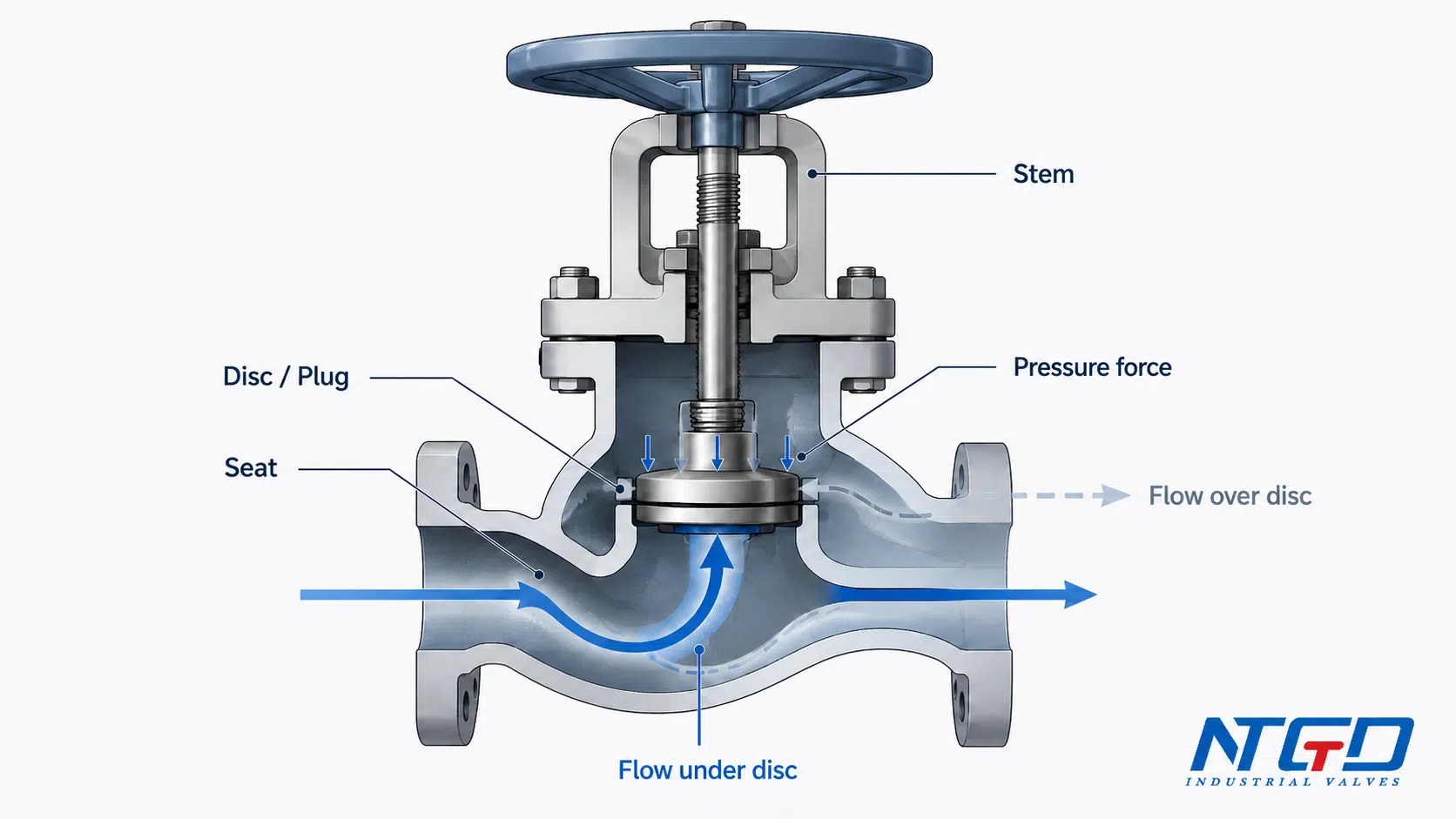
A globe valve is not just a straight pipe with a handwheel. Inside the valve body, the flow must pass through the seat and around the disc or plug. This internal flow path is what makes globe valves useful for throttling and shutoff, but it also makes flow direction important.
In a globe valve, flow direction can affect:
- how pressure acts on the disc or plug;
- how much force is needed to open or close the valve;
- how stable the valve is during throttling;
- how the seat and disc surfaces wear over time;
- how well the valve shuts off under service conditions;
- whether the installed valve matches the intended piping design.
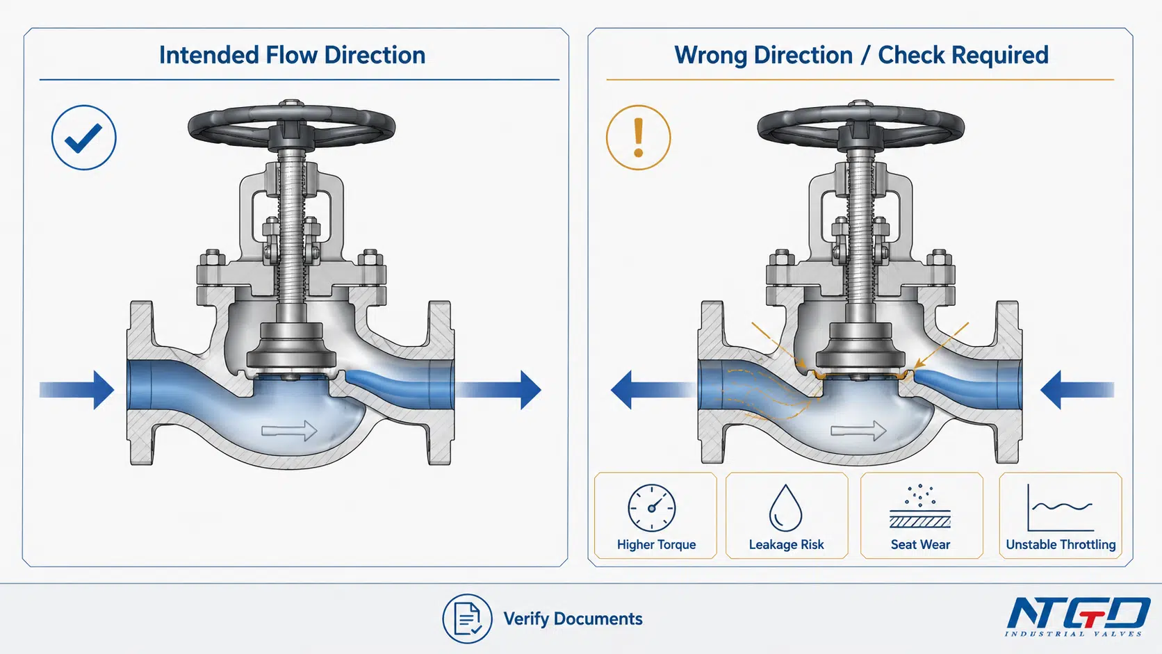
These are not only theoretical differences. Incorrect flow direction may lead to higher operating torque, unstable shutoff, accelerated seat wear, or actuator force problems, depending on the valve size and service condition.
The seat and disc area is the key point. When pressure acts below the disc, it can create an upward force that helps lift the disc against the stem load. When pressure acts above the disc, it can create a downward force that pushes the disc toward the seat. That force balance can affect torque, stem load, actuator sizing, sealing behavior, and control stability.
For readers who need a component-level refresher before reviewing flow direction, NTGD’s globe valve parts and components guide explains how the body, disc or plug, seat, stem, packing, and trim work together.
If the installed direction does not match the intended valve design, the result may be difficult manual operation, undersized actuator force, leakage, vibration, unstable throttling, or faster wear in severe services.
This does not mean one direction is always correct and the other is always wrong. It means the direction must match the valve design and the intended service. A valve installed against its intended flow direction may still physically fit into the pipeline, but it may not perform as expected.
For industrial projects, this matters during:
- RFQ review;
- valve drawing approval;
- installation planning;
- site inspection;
- commissioning;
- troubleshooting after leakage, noise, vibration, or hard operation.
Flow-to-Open vs Flow-to-Close in Globe Valves
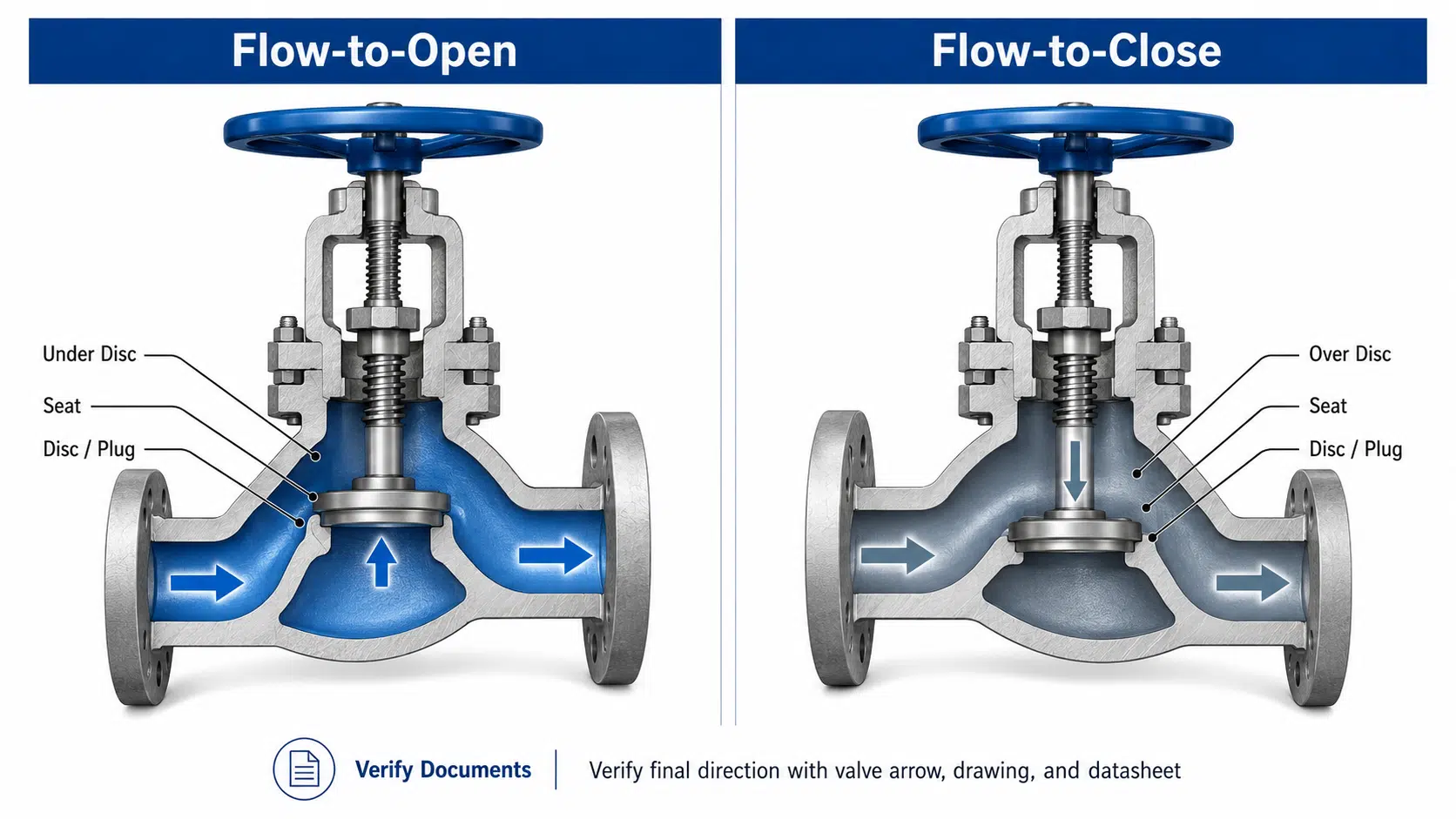
Globe valve flow direction is often explained using two terms: flow-to-open and flow-to-close. These terms describe how the process fluid approaches the disc or plug and how pressure acts on the closure element.
Flow under the disc is common in many general globe valve applications, but it should not be treated as a universal rule. The manufacturer’s arrow, datasheet, drawing, and project documentation remain the final reference.
Flow-to-open: flow under the disc
In a flow-to-open arrangement, the fluid enters from below the disc or plug and moves upward through the seat area. This is often described as flow under the disc or flow under the seat.
This direction is common in many general-service globe valves because the pressure under the disc can help lift the closure element as the valve opens. It can also give a more familiar throttling response in many standard installations.
However, “flow under the disc” should not be written as an absolute rule. The correct direction still depends on the valve design and the manufacturer’s intended flow arrow.
Flow-to-close: flow over the disc
In a flow-to-close arrangement, the fluid approaches from above the disc or plug. This is also called flow over the disc, flow over the seat, or reverse flow.
Reverse flow does not automatically mean the valve is installed incorrectly. In some high-pressure, high-temperature, actuated, or special trim applications, the manufacturer may intentionally specify flow-to-close. In that case, the flow direction arrow and drawing should reflect the intended arrangement.
The mistake occurs when the valve is installed opposite to the manufacturer’s intended direction, not simply because the flow is over the disc.
Flow-to-Open vs Flow-to-Close Comparison Table
| Item | Flow-to-Open | Flow-to-Close |
|---|---|---|
| Common description | Flow under the disc / plug | Flow over the disc / plug |
| Pressure action | Pressure tends to assist opening movement | Pressure tends to assist closing movement |
| Typical use | Common in many general water, oil, gas, and utility services where the valve is designed for flow under the disc | May be specified for selected high-pressure, high-temperature, actuated, or special trim services where pressure-assisted closing is intended |
| Opening / closing effect | Can reduce opening effort in some designs but may increase closing force | Can increase opening force but may help closing force in some designs |
| Sealing / wear implication | Depends on seat design, pressure, medium, and operating cycles | Depends on design; may change seat load, stem load, and wear pattern |
| Control behavior | Often familiar for throttling in many standard applications | May be selected for specific control or pressure conditions |
| How to verify | Body arrow, datasheet, drawing, P&ID, valve tag | Body arrow, datasheet, drawing, P&ID, valve tag |
| Risk if applied incorrectly | Hard operation, leakage, wear, or unstable throttling may occur | Same risk if it conflicts with the intended valve direction |
For terminology calibration only, Crane Engineering also explains flow-to-open and flow-to-close terminology as flow direction relative to the valve plug; for a specific valve, the final direction should still come from the manufacturer’s arrow, drawing, datasheet, and project documentation.
The safest wording is:
Flow-to-open is common, but the correct globe valve flow direction is the direction specified by the manufacturer’s arrow, drawing, and project documentation.
What Does the Flow Direction Arrow on a Globe Valve Mean?
The flow direction arrow on a globe valve is the primary practical clue for installation because it normally represents the manufacturer’s intended flow direction for that valve.
The arrow may be:
- cast into the valve body;
- stamped or engraved on the body;
- marked on a nameplate;
- shown on the drawing or datasheet;
- referenced in the installation instruction.
In many industrial globe valves, the arrow is not decorative. It helps the installer align the valve with the intended internal flow path. The external arrow is linked to the internal seat, disc, and body geometry; it is not just a marking on the outside of the casting.
If the valve is installed against the arrow, the pressure may act on the disc, seat, stem, packing, or actuator in a way that was not intended for that service.
The arrow should be read with the valve documents
The body arrow is usually the first field-level reference, but it should not be the only reference when the service is severe or the installation is unclear.
A good confirmation sequence is:
- check the flow direction arrow on the valve body;
- compare it with the valve drawing or datasheet;
- confirm the process flow direction on the P&ID;
- match the valve tag with the correct line and service;
- verify any special requirement from the manufacturer or project specification.
If the body arrow and project documents appear to conflict, do not resolve the issue by site judgement alone. Check the manufacturer’s drawing, datasheet, or valve tag record before operation.
This is critical for steam, high-pressure, high-temperature, corrosive, dirty, actuated, or throttling services.
What if the arrow is missing or unclear?
If the arrow is missing, covered by paint, damaged, or not visible after installation, do not assume the direction from valve appearance alone.
Guessing from body shape or pipe layout alone can be misleading because the internal seat and disc arrangement may not be obvious from the outside.
Instead, check:
- the valve tag;
- the original purchase specification;
- the manufacturer’s drawing;
- the datasheet;
- the P&ID;
- the line flow direction;
- the installation instruction.
If those documents are not available, the safest action is to ask the valve manufacturer or supplier before operating the valve under pressure.
Does the arrow always mean the same thing on every valve?
Not always. On some valve types, arrows may indicate recommended pressure direction, preferred sealing direction, or manufacturer-specific installation orientation. This article focuses on globe valve flow direction. For a globe valve, the flow direction arrow should be interpreted in the context of the valve’s design and documents, not as a universal rule for all valve types.
Globe Valve Installation Direction: What to Check Before Installation
Globe valve installation direction should be treated as a direction-confirmation task, not as a full installation procedure. The goal is to confirm that the valve’s intended flow path matches the pipeline flow direction before the valve is installed, welded, bolted, insulated, or commissioned.
Check the body arrow before positioning the valve
Before installation, locate the body arrow or marking. Confirm that the pipeline flow direction matches the arrow direction. If the valve is flanged, this check should be made before tightening the bolting. If the valve is welded, it should be confirmed before welding.
For welded globe valves, the flow direction check should be completed before welding, because correction after welding may require rework and additional inspection.
Once a valve is installed in the wrong direction, correction may require downtime, rework, or additional inspection. That is why the direction check should happen early.
Confirm with drawing, datasheet, or P&ID
The body arrow is important, but the drawing and datasheet are the technical basis. The P&ID confirms the process flow direction. The valve tag confirms that the valve being installed is the same valve specified for that line.
This is critical when:
- multiple globe valves look similar at site;
- the valve is supplied for steam or high-temperature service;
- the valve is actuated;
- the line has a bypass or branch connection;
- the valve is installed in a vertical line;
- the body arrow is difficult to see after painting or insulation.
Check service condition
Flow direction may affect operating force and sealing behavior. Before final installation, verify whether the service condition creates any special requirement.
Important service factors include:
- medium;
- pressure;
- temperature;
- pressure drop;
- valve size;
- seat and disc design;
- trim design;
- manual or actuated operation;
- throttling frequency;
- required shutoff performance.
Final Installation Direction Check Table
| Check Item | What to Confirm | Why It Matters |
|---|---|---|
| Body arrow | Arrow direction on the valve body | First practical clue for installation |
| Drawing | Manufacturer’s intended flow path | Confirms the design basis |
| Datasheet | Direction, service, size, pressure class, trim | Prevents using generic assumptions |
| P&ID | Process flow direction | Confirms how the valve fits the piping system |
| Valve tag | Correct valve on the correct line | Avoids mixing similar valves |
| Service condition | Medium, pressure, temperature, throttling duty | May affect flow-to-open or flow-to-close selection |
| Site orientation | Horizontal / vertical line, access, actuator position | Helps avoid installation confusion |
| Manufacturer support | If documents conflict or arrow is unclear | Prevents risky field assumptions |
This direction-confirmation workflow is an important pre-installation check. The actual installation work should still follow the project procedure and the manufacturer’s IOM.
What Happens If a Globe Valve Is Installed Backwards?
A globe valve installed backwards means the valve is installed opposite to its intended flow direction. This does not simply mean “reverse flow exists.” Reverse flow can be intentional in some valve designs. The problem is when the installed direction conflicts with the body arrow, datasheet, drawing, or manufacturer instruction.
The consequences depend on the valve design, pressure, temperature, medium, size, actuator, and operating duty. In some light services, the effect may be limited. In more demanding services, the effect can be more serious.
Harder operation or unexpected torque
If pressure acts on the wrong side of the disc or plug, the force required to open or close the valve may change. A manual valve may feel harder to operate. An actuated valve may require more actuator force than expected.
This is especially important for larger sizes, higher pressure, or frequent operation.
Seat, disc, and sealing wear
Wrong-flow direction can change how the fluid impinges on the seat and disc surfaces. Over time, this may contribute to uneven wear, erosion, vibration, or sealing instability, depending on the medium and pressure drop.
For clean, low-pressure service, the effect may be less obvious. For steam, dirty fluids, high differential pressure, or throttling service, the risk can be higher.
Leakage or unstable shutoff risk
If the valve was designed to seal with pressure acting in a certain direction, reverse installation may reduce shutoff stability. This can appear as leakage, repeated adjustment, or inconsistent shutoff after operation.
The exact behavior depends on seat design, disc design, stem load, packing condition, and differential pressure.
Throttling instability in some control services
Some globe valves are used for throttling or control. In those cases, wrong-flow direction may affect plug force balance, near-closed stability, actuator load, and control response.
This does not mean every globe valve installed backwards will immediately fail. It means the valve may not behave as designed, especially when the service condition is severe.
Wrong-flow Risk Table
| Risk Area | Possible Effect | Depends On |
|---|---|---|
| Operation torque | Valve may be harder to open or close | Size, pressure, stem design, actuator force |
| Sealing | Shutoff may become less stable | Seat design, disc design, differential pressure |
| Wear | Seat or disc wear may increase | Medium, pressure drop, cycles, throttling duty |
| Control stability | Throttling may become unstable in some services | Trim design, actuator, flow condition |
| Pressure drop | Unexpected flow resistance, noise, or pressure loss may occur due to a disrupted internal flow path | Body pattern, opening position, service condition |
| Maintenance | More inspection may be required | Severity of service and operating history |
If backward installation is suspected, the valve should be checked against the valve tag, drawing, datasheet, P&ID, and manufacturer instruction before continued operation, especially in high-pressure, steam, hazardous, actuated, or critical services.
If the valve has already operated in the wrong direction and shows leakage, unstable shutoff, abnormal torque, noise, or vibration, the issue may have moved beyond a direction check and into a maintenance or troubleshooting case.
For recurring leakage, abnormal torque, poor shutoff, noise, or vibration after operation, use NTGD’s globe valve maintenance and troubleshooting guide to separate flow-direction issues from component wear, packing problems, or seat damage.
Do Angle, Y-pattern, or Z-pattern Globe Valves Change the Flow Direction Rule?
Different globe valve body patterns change the internal flow path, but they do not remove the need to confirm flow direction.
Z-pattern globe valves
A Z-pattern or T-pattern globe valve is the common body arrangement many users imagine when discussing globe valve flow direction. The flow path changes direction through the seat area, which is why pressure drop and flow direction are both important.
Angle globe valves
An angle globe valve changes the flow path by about 90 degrees. It can combine the function of a globe valve and an elbow in one body layout. This body geometry affects the piping arrangement and internal path, but the flow direction still needs to follow the valve body arrow, drawing, datasheet, or manufacturer instruction.
For product-specific details on the 90° body pattern, service range, and engineering documentation, review NTGD’s angle globe valve page instead of expanding the angle-pattern topic inside this flow-direction guide.
The 90° body turn can make the relationship between the body arrow and pipeline direction less intuitive than a straight layout, so drawing review is still important before installation.
For the keyword angle globe valve flow direction, the correct treatment in this guide is a short boundary note: angle body geometry changes the flow path, but it does not replace direction confirmation.
Y-pattern globe valves
A Y-pattern globe valve usually provides a straighter internal path than a Z-pattern design. It may reduce flow resistance compared with some conventional globe valve body forms, depending on the design. However, the correct flow direction still must be verified from the manufacturer’s marking and documents.
Like other globe valve body patterns, a Y-pattern design still follows the same direction confirmation process: body marking first, then drawing, datasheet, and project documents.
Pattern Caveat Table
| Body Pattern | Flow Path Note | How to Treat Flow Direction |
|---|---|---|
| Z-pattern / T-pattern | Common globe valve body path with direction change through the seat area | Confirm arrow and documents |
| Angle pattern | Flow path turns about 90 degrees | Light mention only; confirm arrow and documents |
| Y-pattern | Straighter path than many Z-pattern designs | Light mention only; confirm arrow and documents |
| Final rule | Body geometry affects path, not the verification method | Do not guess from shape alone |
For a broader comparison of Z-pattern, Y-pattern, angle-pattern, and special globe valve configurations, use the globe valve types and selection guide rather than turning this article into a body-pattern hub.
Different body patterns change the internal flow path, but they do not change the basic confirmation rule: follow the manufacturer’s marking and documents. Detailed angle globe valve or Y-pattern selection should be handled by the relevant product or technical page.
Final Direction Check Before RFQ, Installation, or Commissioning
Flow direction should be confirmed as early as the RFQ or drawing review stage, and then rechecked before installation, welding, bolting, insulation, or commissioning. This helps avoid rework, site confusion, and delayed commissioning later in the project.
The minimum information needed includes:
- valve type and tag number;
- size and pressure class;
- body pattern;
- end connection;
- medium;
- pressure and temperature;
- normal flow direction in the pipeline;
- whether the valve is manual or actuated;
- drawing or datasheet;
- P&ID or line diagram;
- any special throttling or shutoff requirement.
A simple final check is:
- Is the valve a globe valve or another valve type?
- Is there a visible arrow or body marking?
- Does the arrow match the pipeline flow direction?
- Does the drawing confirm the same direction?
- Does the datasheet specify flow-to-open or flow-to-close?
- Does the service condition require special confirmation?
- Is the valve tag matched to the correct line?
- If any answer is uncertain, has the manufacturer been consulted?
This check is especially useful when valves are installed in steam service, high-pressure service, vertical piping, bypass lines, or actuated control service.
FAQ
Do globe valves have a flow direction?
Yes. In most industrial applications, a globe valve should be treated as a valve with an intended flow direction. Confirm that direction with the body arrow, datasheet, drawing, P&ID, valve tag, or manufacturer instruction before installation.
Which way does a globe valve flow?
Many globe valves are designed for flow-to-open, where the fluid enters from under the disc or plug. However, this is not universal. Always verify the flow direction arrow and manufacturer documents for the specific valve.
What does the arrow on a globe valve mean?
The arrow usually indicates the manufacturer’s intended flow direction for that valve. It should be checked before installation and compared with the project drawing or datasheet when the service is critical.
What if there is no flow direction arrow on the valve body?
Do not guess from the body shape alone. Check the valve drawing, datasheet, P&ID, valve tag, or installation instruction. If the information is still unclear, ask the manufacturer or supplier before operating the valve.
Can a globe valve be installed backwards?
A globe valve may physically fit into the pipeline in the opposite direction, but that does not mean the installation is acceptable. If the valve is installed against its intended flow direction, torque, sealing, wear, pressure drop, or control behavior may be affected.
What happens if a globe valve is installed backwards?
Possible effects include hard operation, leakage, unstable shutoff, seat or disc wear, unexpected pressure drop, or unstable throttling. The actual result depends on design, pressure, temperature, medium, and operating duty.
Are globe valves bidirectional?
Most industrial globe valves should not be assumed to be bidirectional. Some special designs or applications may allow different flow directions, but this must be stated in the manufacturer’s datasheet or drawing. If the service requires bidirectional flow, confirm this during valve selection rather than at site.
Does an angle globe valve have a different flow direction?
An angle globe valve changes the flow path by about 90 degrees, but the correct direction still depends on the body arrow, drawing, datasheet, and manufacturer instruction. The angle body shape alone should not be used as the final direction rule.
Conclusion
Globe valve flow direction should be confirmed before the valve is installed or operated. The body arrow is usually the first practical clue, but the final decision should be checked against the drawing, datasheet, P&ID, valve tag, and manufacturer instruction.
Flow-to-open and flow-to-close describe how fluid approaches the disc or plug. Flow under the disc is common in many globe valve applications, but it is not a universal rule. Reverse flow can be intentional in some designs, while wrong-flow installation means the valve is installed against its intended direction.
For industrial service, the safest approach is to treat flow direction as part of the valve specification, not as a field guess.
Ultimately, correct globe valve flow direction is a design and documentation issue, not an appearance-based guess. The safest final check is to match the body arrow, drawing, datasheet, P&ID, valve tag, and service condition before the valve is operated.
Application / Specification Support
When field documents are missing, conflicting, or difficult to interpret, flow direction should be confirmed before RFQ approval or site installation.
If the correct globe valve flow direction is unclear, NTGD can help review the application before RFQ, installation, or commissioning.
For direction confirmation, prepare the following information:
- valve tag;
- valve drawing;
- datasheet;
- P&ID or line sketch;
- medium;
- pressure and temperature;
- pipe flow direction;
- whether the valve is manual or actuated;
- installation orientation;
- any throttling or shutoff requirement.

Once the intended flow direction and service conditions are clear, the industrial globe valves page can serve as the product-level bridge for available NTGD globe valve categories and specification support.
With this information, NTGD engineers can review the application, compare the valve design with the service condition, and help confirm the intended flow direction and any installation considerations before RFQ, installation, or commissioning.
