Имя автора: Брюс Чжэн
Роль автора: Соучредитель и инженер по клапанам в NTGD Valve
Био автора: Брюс Чжэн - соучредитель и инженер по клапанам в компании NTGD Valve, специализирующейся на выборе промышленных клапанов, их применении и техническом контенте для глобальных покупателей B2B.
Последнее обновление: 15 июня 2026 года
Gate valve flow direction is often treated as a simple question, but the correct answer depends on the valve design, body marking, manufacturer documentation and installation orientation. This gate valve flow direction guide focuses on ordinary industrial gate valves, not knife gate valves or globe valves.
For most standard industrial gate valves used for isolation service, the valve can usually be installed for either pipeline flow direction: it allows flow through a straight passage when fully open and can isolate pressure from either side when fully closed, provided the design supports bidirectional sealing. However, the correct installation still depends on body markings, the manufacturer’s installation, operation and maintenance (IOM) manual, seat or wedge design, pressure-side requirements and installation orientation.
The safest practical rule is:
Treat ordinary gate valves as usually bidirectional for isolation service, but verify the body arrow, nameplate, datasheet, drawing, IOM and installation orientation before final installation.
This article explains how to judge gate valve flow direction, when bidirectional flow is acceptable, what a body arrow may mean, and how to avoid common installation-direction and orientation mistakes.

Quick Answer: Does Flow Direction Matter on a Gate Valve?
For a standard gate valve used for on-off isolation, flow direction is usually less critical than it is for a globe valve or check valve. When the gate is fully open, the flow path is relatively straight through the valve body. When the gate is fully closed, the gate or wedge seals against the seats to isolate flow.
This is why many standard gate valves are treated as suitable for bidirectional flow. In practical terms, the valve can often stop flow from either side when it is correctly selected, installed and operated.
For engineering review, the decision is not simply whether a gate valve is “directional” or “non-directional.” The real question is whether this specific valve design, service condition and manufacturer instruction allow bidirectional installation without reducing sealing reliability, operating performance or maintenance access.
The practical answer for standard industrial gate valves
For most ordinary industrial gate valves, the flow direction is not fixed in the same way as a check valve. The valve can normally be installed for either flow direction if the valve design, seat construction and manufacturer instructions allow it.
This is especially common for isolation service where the valve is either fully open or fully closed. The gate moves perpendicular to the flow path, not along the flow direction. That makes the valve different from designs where the internal flow path is intentionally directional.
When a general bidirectional rule is not enough
A general bidirectional rule is not enough when:
- the valve body has a directional arrow;
- the manufacturer’s IOM specifies a preferred installation direction;
- the valve has a special seat, wedge or pressure-side design;
- the valve is large, high pressure or actuated;
- the service involves steam, corrosive media, dirty water, slurry-like media or severe cycling;
- the project requires a defined pressure side for testing, sealing or maintenance;
- the valve is not an ordinary gate valve, such as a knife gate valve or other special-purpose valve.
In these cases, the correct installation direction is not decided by generic gate valve theory. It is decided by the valve design and the manufacturer’s controlled documents.
Ignoring these checks can lead to wrong pressure-side installation, abnormal operating torque, leakage during commissioning or poor access for later maintenance.
How Flow Direction Works in a Standard Gate Valve
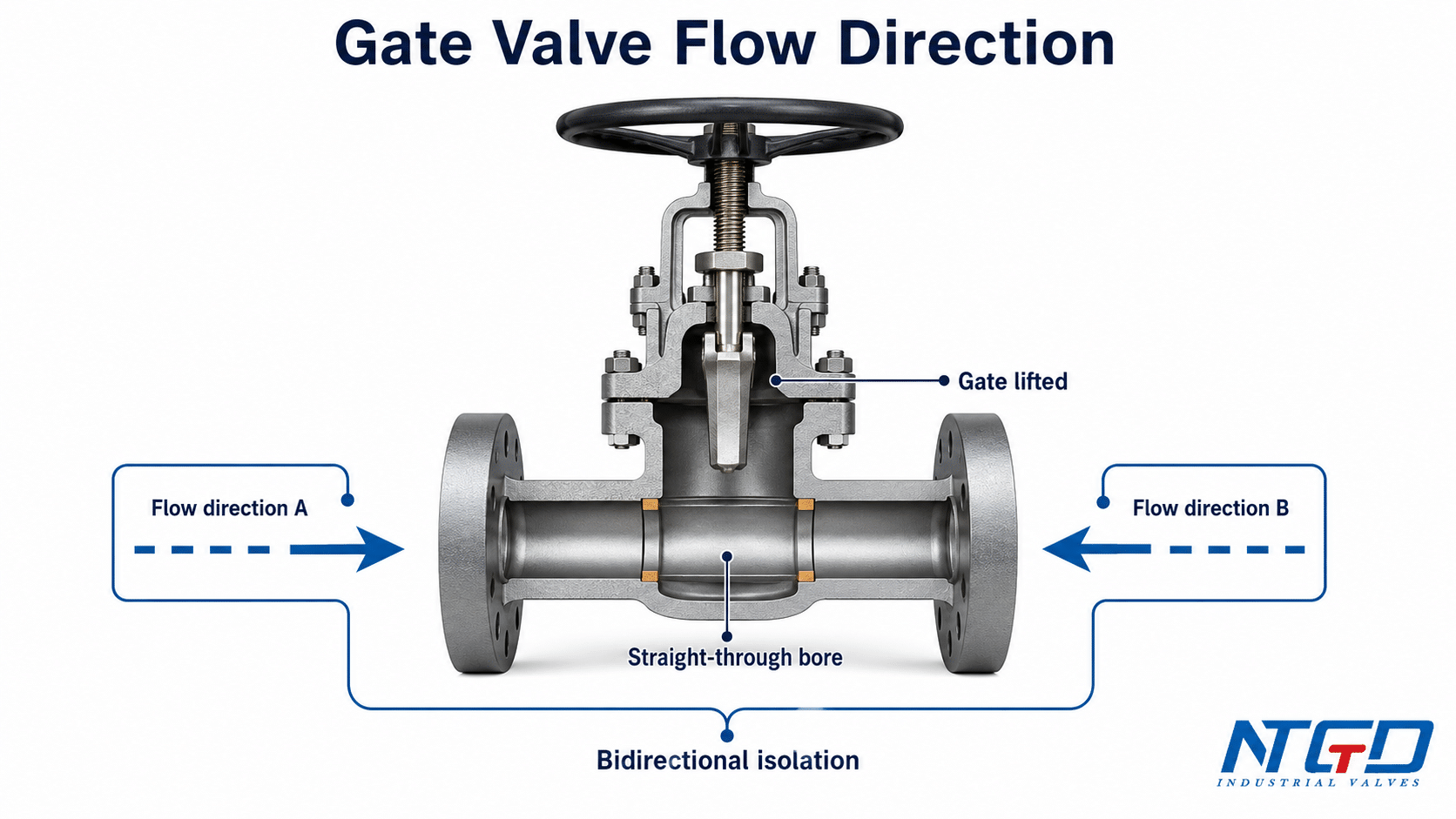
A standard gate valve controls flow by moving a gate or wedge into and out of the flow path. When the valve is fully open, the gate is lifted away from the flow passage. When the valve is closed, the gate moves down between the seats and blocks the passage.
This basic geometry explains why many gate valves are considered suitable for bidirectional isolation. The flow path through the valve body is relatively straight, and the closure member does not depend on one specific flow direction in the same way a check valve disc or globe valve plug often does.
Straight-through flow path and full-open isolation service
In the full-open position, a gate valve provides a mostly straight flow passage. The gate is lifted out of the bore, reducing obstruction in the flow path. This is why gate valves are commonly selected for isolation service in pipelines where low pressure drop is required when the valve is open.
A standard gate valve is not designed to continuously regulate flow in a partially open position. Its core role is isolation: open the line or shut off the line.
Why standard gate valves are usually treated as bidirectional
Standard gate valves are often treated as bidirectional because the gate seals between two seats and can isolate pressure from either side, provided the valve design supports that service. For many common wedge gate valves and parallel gate valves, there is no single “inlet side” that must always face upstream in ordinary isolation service.
This does not remove the need for project review. The valve’s actual direction capability depends on the detailed design, seat arrangement, body marking, testing requirement and manufacturer documentation.
A standard gate valve flow-path diagram is useful here because it shows why the gate moves across the flow path instead of relying on a one-way internal flow route.
Why gate valves should not be used for throttling
A gate valve should generally not be used for throttling. In a partially open position, high-velocity flow can pass around the gate and seats, causing vibration, erosion, noise, seat damage or unstable operation. This is especially important in steam, dirty water, corrosive service or media with suspended solids.
Using a gate valve as a throttling valve can also create confusion about flow direction. The valve may appear to “work” in a partially open position, but the internal wear pattern can be very different from normal on-off isolation service.
For additional non-NTGD technical background on open-bore isolation duty and throttling limits, Valve Magazine’s gate valve fundamentals provides a useful industry reference.
When a Gate Valve Is Bidirectional — and When You Still Need to Check
Many gate valves are bidirectional in normal isolation service, but not every gate valve should be installed without direction verification. The safest approach is to classify the valve design first, then check the manufacturer’s documentation.
| Gate valve design or condition | Is it usually bidirectional? | What to verify before installation |
|---|---|---|
| Standard wedge gate valve | Usually yes | Body marking, wedge type, seat arrangement, IOM and pressure class |
| Параллельная задвижка | Usually yes | Seat arrangement, pressure direction, sealing design and IOM |
| Задвижка с упругим седлом | Often yes, depending on design | Water service requirements, resilient seat compression, manufacturer direction notes and IOM |
| Задвижка с металлическим седлом | Often yes, but service-dependent | Seat design, high-temperature service, leakage requirements, pressure-side review and IOM |
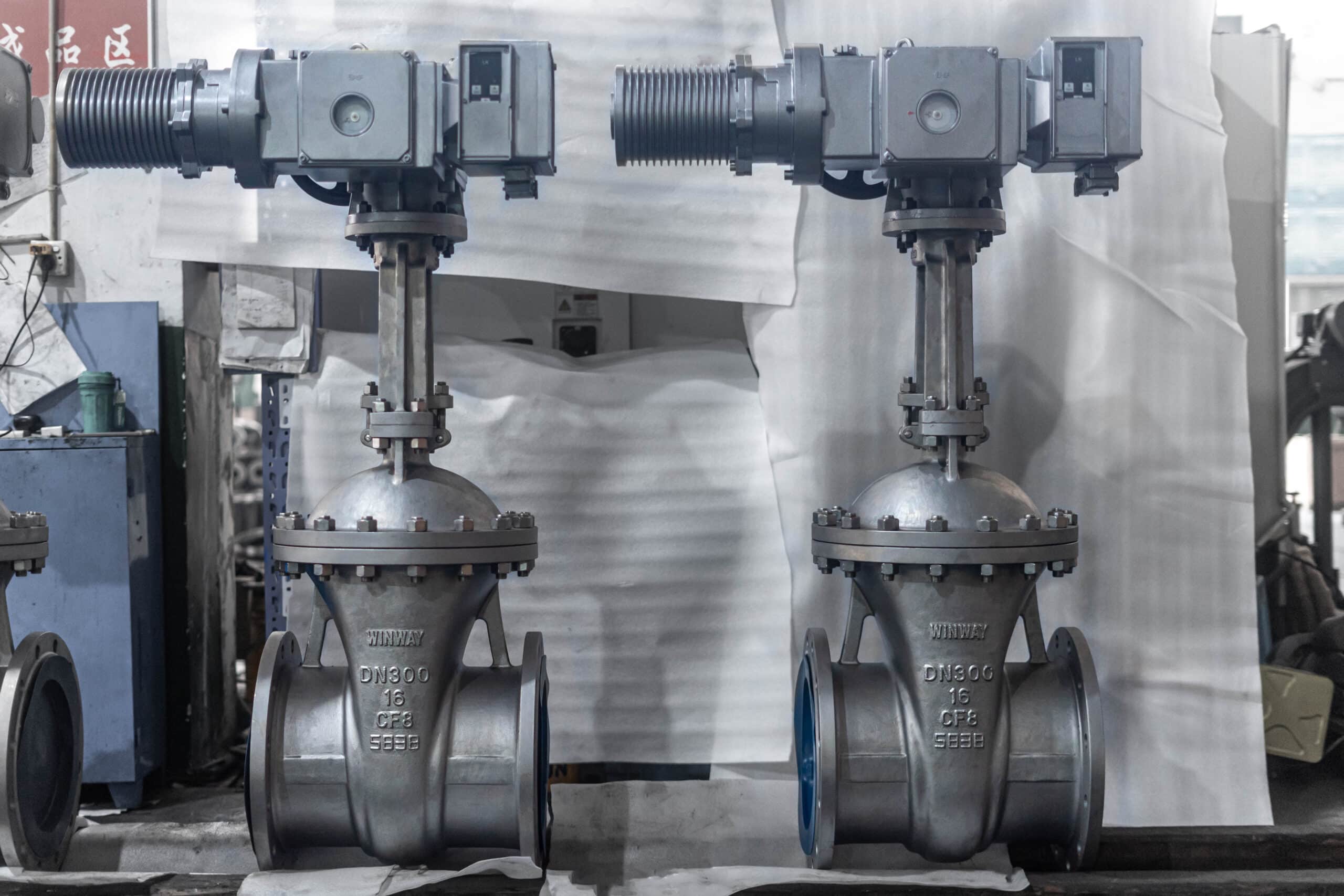
| Large-size gate valve | Needs closer review | Body marking, lifting position, pipe support, gearbox or actuator orientation and maintenance access |
| High-pressure gate valve | Needs closer review | Preferred pressure side, test direction, pressure-seal or bonnet design if applicable, and project specification |
| Actuated gate valve | Needs closer review | Actuator mounting direction, torque setting, travel limit, limit switch position and commissioning check |
| Ножевая задвижка | Separate topic | Seat side, pressure side, slurry / dirty service requirement and unidirectional or bidirectional construction |
Standard wedge and parallel gate valves
In many industrial applications, wedge gate valves and parallel gate valves are selected because they can provide straight-through isolation with flow from either direction. This is one reason gate valves are common in water, oil, gas, steam and general process piping.
Still, “standard” should not be guessed from the external appearance alone. Two valves that look similar from the outside may have different seat designs, trim materials, pressure ratings or manufacturer instructions.
Seat, wedge and pressure-side exceptions
Flow direction may matter when the seat or wedge design is not symmetrical, when the valve relies on a preferred pressure side, or when the manufacturer has tested or certified the valve for a particular installation direction.
For example, a resilient seated gate valve used in water service may have different sealing behavior from a metal seated gate valve used in high-temperature service. A high-pressure wedge gate valve may also require closer review of pressure side, test direction and operating torque.
If the sealing route is unclear, compare resilient seated and metal seated gate valves before assuming the same leakage expectation or service limit.
The correct question is not only “Is a gate valve bidirectional?” It is:
Is this specific gate valve design suitable for bidirectional service under this media, pressure, temperature and installation condition?
Large, high-pressure or actuated gate valves
Large, high-pressure and actuated gate valves need more careful installation review because flow direction is only one part of the installation decision. The project should also confirm:
- actuator or gearbox access;
- stem clearance;
- support for valve weight;
- lifting and handling points;
- valve orientation;
- torque or travel limit settings;
- inspection and maintenance access;
- manufacturer IOM requirements.
For these valves, the drawing and IOM are more important than a general statement about gate valve flow direction.
A knife gate valve should not be judged by ordinary wedge gate valve assumptions, because its seat side, pressure side and unidirectional or bidirectional construction can directly affect shutoff performance. Applying the wrong direction rule can increase leakage risk or seat damage in dirty or slurry service.
Body Arrow, Nameplate and IOM: What to Verify Before Installation
A body arrow on a gate valve should never be ignored. However, it also should not be interpreted without context. Depending on the valve and manufacturer, an arrow may refer to flow direction, preferred pressure direction, installation reference, test reference or another manufacturer-specific requirement.
The manufacturer’s IOM should always take priority over general online explanations.
What a body arrow may mean
A body arrow can mean different things depending on the valve design. It may show the recommended flow direction. It may show the preferred pressure direction. It may also relate to seat design, test condition or installation reference.
For a gate valve, do not assume that every arrow means the same thing as a check valve flow arrow. A check valve arrow usually indicates the required one-way flow direction. A gate valve arrow may require more careful interpretation.
| Marking or document | What it can tell you | Распространенная ошибка |
|---|---|---|
| Стрела для тела | Preferred flow direction, pressure direction or manufacturer-specific installation reference | Assuming the arrow is decorative, or assuming it always means the same thing as a check-valve arrow |
| Nameplate | Size, pressure class, material, standard or manufacturer data | Ignoring project-specific valve details |
| Информационный лист | Design, material, pressure, temperature and service information | Treating the valve as a generic gate valve |
| Рисование | Face-to-face, connection, actuator and orientation details | Installing before checking clearance and operator access |
| IOM / installation manual | Manufacturer-specific installation, operation, maintenance and safety instructions | Replacing IOM with general rules |
If a body arrow is present and the IOM is not immediately available, do not treat the valve as non-directional by default. The conservative approach is to pause the final installation decision, request the manufacturer’s documentation, or treat the arrow as a preferred flow or pressure reference until the documentation confirms its meaning.
Why the manufacturer’s IOM comes before general rules
The IOM is the controlled document for that valve model. It may include instructions for installation direction, orientation, handling, operation, maintenance, torque setting, actuator adjustment and safety precautions.
If the IOM conflicts with a general statement that “gate valves are bidirectional,” follow the manufacturer’s instruction for the actual valve.
For API-related marking, testing and documentation review, use NTGD’s Стандарты API для задвижек as a supporting reference, then follow the manufacturer’s IOM for the specific model.
Documents to check: datasheet, drawing, nameplate and installation manual
Before installation, the engineering or installation team should check at least four sources:
- Информационный лист — confirms valve type, pressure class, material, trim and service limits.
- Рисование — confirms dimensions, end connection, actuator position and orientation.
- Nameplate / marking — confirms key identification and any visible direction marking.
- IOM — confirms manufacturer-specific installation and operation requirements.
For project procurement, these documents should also be requested before final approval if direction or orientation is critical.
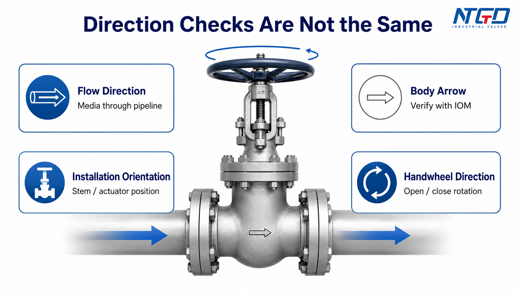
Flow Direction vs Installation Orientation vs Handwheel Operating Direction
Many installation mistakes come from mixing different “direction” questions. Flow direction, body arrow, installation orientation and operating direction are related, but they are not the same thing.
A practical review should separate four ideas:
- Направление потока means the direction of process media through the pipeline.
- Body arrow or marking may indicate preferred flow, pressure direction, test reference or another manufacturer-specific instruction.
- Ориентация при установке means the position of the stem, bonnet, gearbox, handwheel or actuator.
- Operating direction means the direction the handwheel or actuator turns to open or close the valve.
These four concepts are easier to review in a direction-and-orientation diagram because the flow path, body marking, stem position and handwheel rotation are different reference points.
| Concept | Что это значит | Что проверить | Распространенная ошибка |
|---|---|---|---|
| Направление потока | Direction of media through the pipeline | Valve design, body arrow, IOM and process flow | Assuming every valve type has the same rule |
| Body arrow / marking | Manufacturer marking on the valve body | Meaning in the IOM, datasheet or drawing | Assuming it is decorative or assuming it always means check-valve-style one-way flow |
| Ориентация при установке | Position of stem, bonnet, gearbox, handwheel or actuator | Drawing, access, clearance, support and safety | Treating stem position as a flow-direction decision instead of an access, support and maintenance decision |
| Operating direction | Direction the handwheel or actuator turns | Handwheel marking, gearbox, actuator setting and IOM | Treating clockwise / counterclockwise handwheel rotation as pipeline flow direction |
Flow direction: medium movement through the pipeline
Flow direction describes where the process media enters and exits the valve. In a pipeline drawing, this is usually shown as the process flow direction. For a standard gate valve, this may be allowed from either side, but the final decision depends on the specific valve.
Installation orientation: stem, bonnet, handwheel and actuator position
Installation orientation describes how the valve is positioned in the pipeline. The stem may be vertical, horizontal or in another approved position depending on the valve design and site conditions.
Orientation affects access, packing performance, actuator clearance, debris accumulation, maintenance and long-term reliability. It is not the same as flow direction.
Operating direction: clockwise and counterclockwise handwheel movement
Operating direction describes how the valve is opened or closed. Many manual valves use clockwise rotation to close, but the final answer depends on the handwheel marking, gearbox, actuator setting and manufacturer instruction.
This is why “which direction do you turn a gate valve to close?” should not be treated as the same question as “which way should the flow go through a gate valve?”
Gate Valve vs Globe Valve vs Check Valve vs Knife Gate Valve Flow Direction
Different valve types have different flow-direction logic. A key risk in installation is applying the rule for one valve type to another valve type.
| Тип клапана | Typical direction rule | Почему это важно | Current article handling |
|---|---|---|---|
| Standard gate valve | Usually bidirectional, subject to design and IOM | Straight-through isolation service | Основная тема |
| Шаровой клапан | Often directional | Internal flow path and plug / seat arrangement are direction-sensitive | Boundary note only |
| Обратный клапан | Direction-sensitive | Designed to allow flow in one direction and prevent reverse flow | Boundary note only |
| Ножевая задвижка | Depends on seat side and design | Unidirectional and bidirectional knife gate designs differ | Separate technical topic |
| Ball valve / butterfly valve | Depends on design and seal arrangement | Some designs are bidirectional; some have preferred direction | Light mention only; do not apply as a gate valve rule |
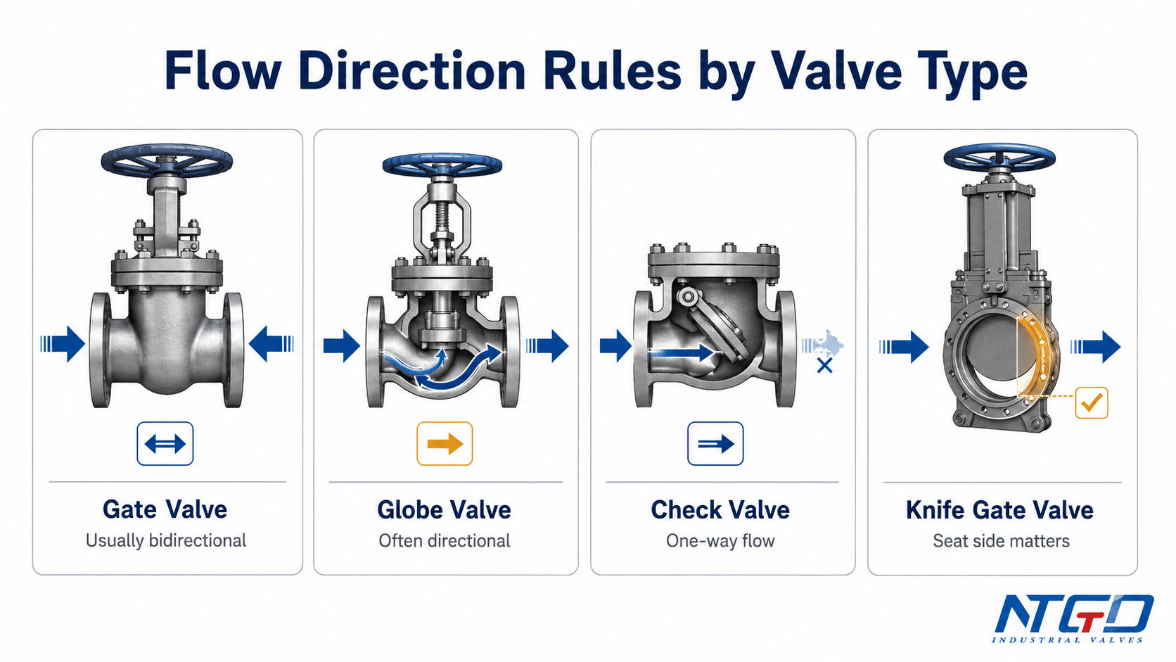
Why gate valves are different from globe valves
A gate valve uses a gate or wedge that moves into the flow path to stop flow. A globe valve uses a plug and seat arrangement with a more directional internal flow path. For this reason, the flow direction logic of a globe valve should not be copied directly to a gate valve.
For a deeper structural comparison, review NTGD’s gate valve and globe valve comparison before applying globe-valve flow-direction rules to a gate valve.
Why check valves are direction-sensitive
A check valve is designed to permit flow in one direction and prevent reverse flow. Its arrow normally indicates the required flow direction. Installing a check valve backwards can prevent normal flow or stop the valve from performing its backflow-prevention function.
A gate valve is not a check valve. It is an isolation valve, not a one-way valve.
Why knife gate valves require separate seat-side verification
Knife gate valves are often used in slurry, wastewater, pulp and dirty service. Their direction logic may depend strongly on seat side, pressure side and whether the knife gate valve is unidirectional or bidirectional.
For that reason, ordinary gate valve flow direction should not be used as the full rule for knife gate valve installation.
Gate Valve Installation Direction Checklist
A gate valve installation direction checklist should focus on direction-related checks, not on replacing the manufacturer’s installation manual. The goal is to prevent the most common direction, marking and orientation mistakes before the valve is placed into service.
This checklist is not a replacement for the valve IOM or project installation procedure. It is a direction and orientation review tool.
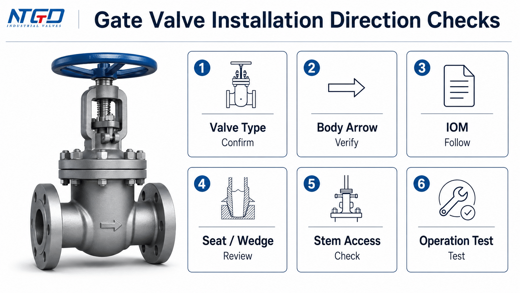
| Проверить товар | Почему это важно | Что проверить |
|---|---|---|
| Confirm valve type | Gate, globe, check and knife gate valves use different direction rules | Valve tag, datasheet and drawing |
| Check body arrow | A visible arrow may indicate preferred direction, pressure side or manufacturer reference | Body marking, datasheet and IOM |
| Review IOM | Manufacturer instructions override general rules | Installation direction, orientation and safety notes |
| Confirm seat and wedge design | Some designs may have preferred pressure direction | Datasheet and technical drawing |
| Confirm service condition | Steam, dirty water, corrosive media or solids may affect orientation and wear | Media, pressure, temperature and solids |
| Check stem and handwheel access | Operation and maintenance need clearance | Layout drawing and site access |
| Check actuator or gearbox position | Large or actuated valves need torque and travel review | Actuator manual, limit switch, wiring and control access |
| Confirm support and alignment | Poor alignment can stress the valve body and flanges | Pipe support and flange alignment |
| Test operation after installation | Abnormal torque may indicate direction, alignment or actuator setting issue | Manual operation or actuator test |
| Inspect leakage after commissioning | Confirms sealing behavior under actual service | Site test procedure and project requirements |
Before installation: direction, marking and design checks
Before installation, confirm that the valve is the correct valve type and design. Then check the body marking, nameplate, datasheet, drawing and IOM. If a body arrow is present, do not rely only on visual interpretation. Confirm what the arrow means in the documentation.
If the valve has special seats, resilient sealing, metal seats, pressure-seal bonnet, bypass arrangement or actuator package, direction and orientation review becomes more important.
During installation: alignment, support and accessibility checks
During installation, the direction-related review should stay focused on whether the valve is positioned as required by the drawing and IOM. The installer should confirm pipeline alignment, body marking direction, stem or actuator position, support condition and access for operation.
This section should not replace the site installation procedure. Flange bolting, gasket handling, welding practice, torque values and pressure testing should follow the project procedure and manufacturer instructions.
After installation: operation, leakage and abnormal torque checks
After installation, operate the valve according to the manufacturer’s instruction and site procedure. The valve should open and close smoothly within expected torque limits. Abnormal torque, unusual noise, stem movement problems or leakage should be investigated before the valve is placed into long-term service.
Do not attempt correction on a pressurized line without following site isolation and depressurization procedures.

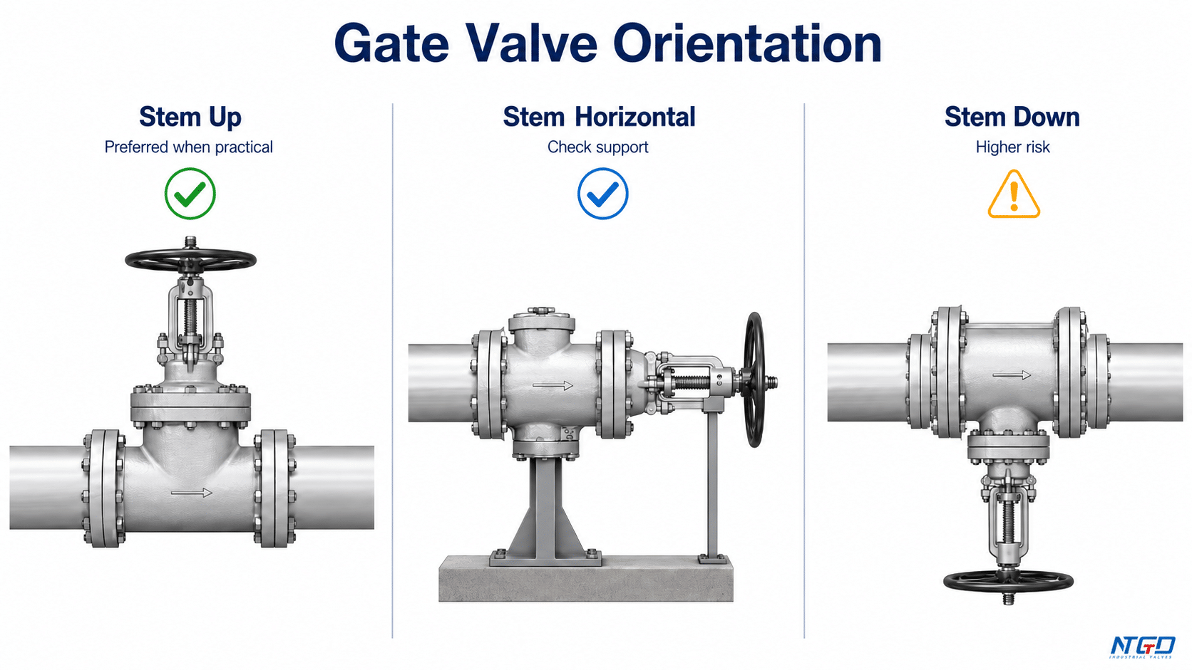
Gate Valve Orientation: Stem, Handwheel and Pipeline Position
Gate valve orientation is not the same as gate valve flow direction. A valve may be acceptable for bidirectional flow but still have restrictions or preferences for stem, bonnet, gearbox or actuator position.
For many installations, stem-up orientation is preferred when practical because it supports access, operation, drainage and packing behavior. However, orientation rules depend on the valve design, line position, site layout and manufacturer approval.
| Orientation issue | Возможные последствия | Что проверить |
|---|---|---|
| Stem-up position | Usually preferred for access, drainage and long-term operation | Site layout, drawing and IOM |
| Horizontal stem | May be acceptable, but valve size, gate weight or actuator weight can affect support and operation | Manufacturer approval, valve support, actuator weight and maintenance access |
| Stem-down / upside-down | Can increase debris accumulation, packing concerns, drainage problems and maintenance difficulty | Manufacturer approval, service condition and cleaning / maintenance access |
| Rising stem clearance | Insufficient clearance can prevent full opening or create access problems | Open-stem travel, overhead space and operator position |
| Gearbox or actuator access | Poor access affects torque setting, limit switch adjustment, wiring and maintenance | Operator position, service platform, control wiring and actuator manual |
| Buried service | Requires planned operation access rather than simple visual access | Extension stem, valve box, operating key and project drawing |
Stem-up orientation as the preferred position when practical
A vertical stem-up orientation is often preferred because it keeps the handwheel, stem and bonnet area accessible. It can also reduce the chance of debris settling in areas that affect operation, depending on service and valve design.
This does not mean every non-vertical orientation is automatically wrong. It means the project should confirm whether the selected orientation is approved for the valve and service.
Horizontal installation: acceptable only when design and access allow
Horizontal installation can be acceptable for some gate valves, especially when the manufacturer permits it and the valve is properly supported. For larger valves, the weight of the gate, stem, bonnet, gearbox or actuator may affect operation and alignment.
The installation team should check whether the valve can be operated, inspected and maintained in the selected position.
Rising stem, OS&Y, gearbox and actuator clearance
Rising stem and OS&Y gate valves need enough clearance for stem travel. If there is not enough space above the valve, the valve may not fully open. Gear-operated and actuated gate valves also need space for operation, maintenance access, wiring and control equipment.
For visual position indication specifically, NTGD’s Направляющая клапана OS&Y explains why visible stem movement matters in field checks.
This is an orientation issue, not a flow direction issue.
For clearance trade-offs, compare rising stem and non-rising stem gate valves before finalizing the installation envelope.
Buried, large-size and special-service gate valves
Buried gate valves may need a valve box, extension stem or special access arrangement. Large-size gate valves may need additional pipe support or lifting planning. Valves in steam, corrosive or dirty service may need closer review of packing, drainage, debris and maintenance access.
For these applications, the drawing and IOM should be reviewed before installation.
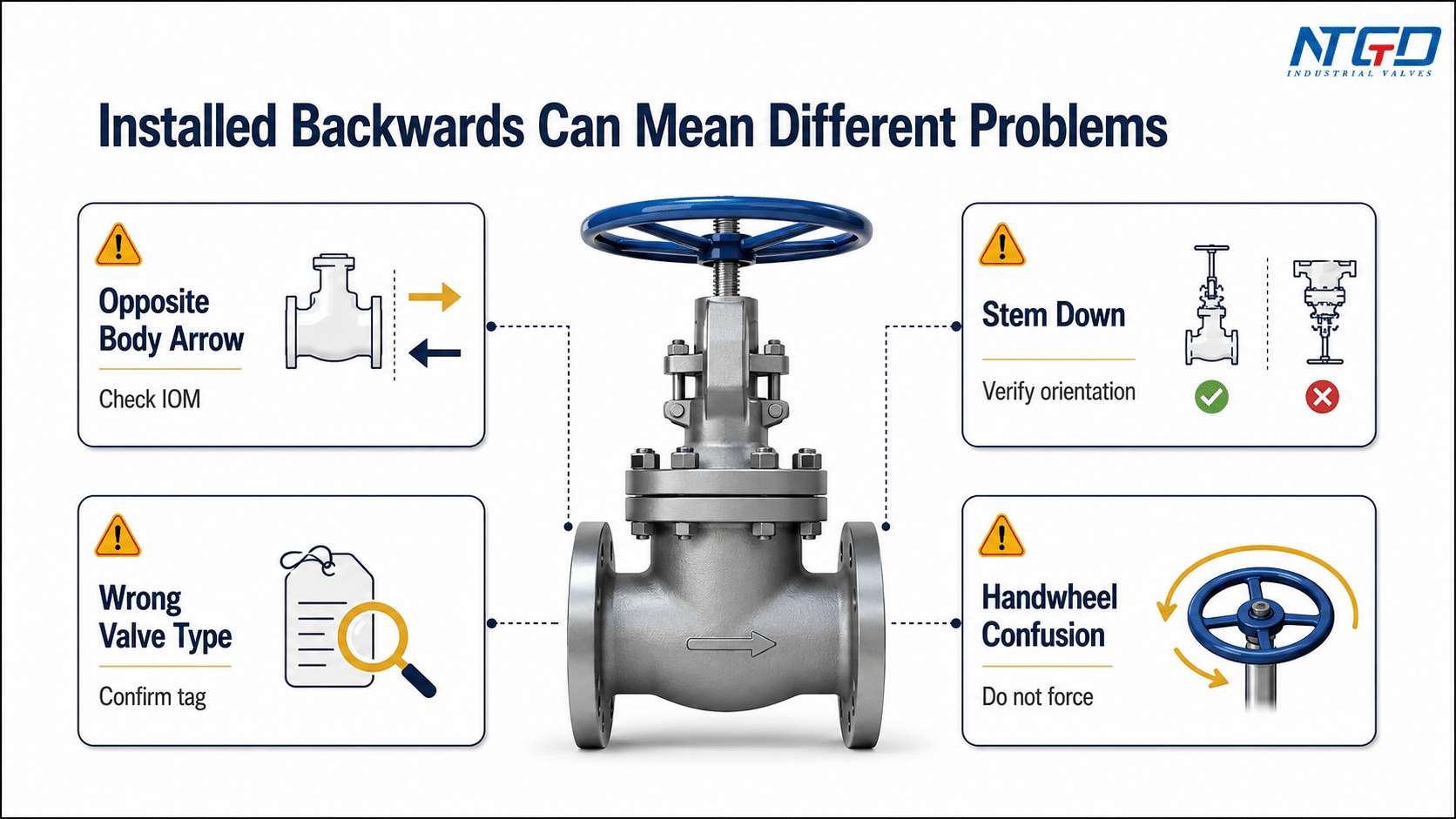
What Happens If a Gate Valve Is Installed Backwards or Upside Down?
In field discussion, “installed backwards” can refer to four different problems: flow opposite a body arrow, stem-down orientation, wrong valve type, or confusion about handwheel operation.
Before correcting the valve, identify which problem actually exists.
| “Backwards” meaning | Possible issue | Что проверить | What not to do |
|---|---|---|---|
| Flow direction opposite the body arrow | May cause wrong pressure-side installation, abnormal torque, leakage during commissioning or reduced sealing reliability, depending on valve design | IOM, datasheet, body marking and pressure-side requirement | Do not assume the body arrow is decorative |
| Stem-down or upside-down position | May increase debris, packing, drainage or maintenance-access risk | Drawing, orientation note and service condition | Do not rotate or remove the valve while the line is pressurized |
| Wrong valve type installed | Globe, check or knife gate logic may differ from ordinary gate valve logic | Valve tag, body shape and project specification | Do not apply gate valve rules to another valve type |
| Handwheel direction confusion | Operator may think the valve is opening when it is closing | Handwheel marking, gearbox and IOM | Do not force the handwheel |
| Actuator mounted incorrectly | Travel limits, torque settings or control feedback may be wrong | Actuator manual, wiring diagram and commissioning test | Do not energize without verification |
Installed backwards can mean different problems
If a standard gate valve is installed opposite the process flow direction, it may still function if the valve is designed for bidirectional service and no preferred direction is specified. But if the valve has a body arrow or manufacturer instruction, the installation must be checked.
The correct response is not automatic removal. The correct response is documentation review, risk assessment and safe site procedure.
Upside-down or stem-down installation risks
Upside-down or stem-down installation can create practical risks. Debris may collect in unwanted areas, packing performance may be affected, maintenance access may become difficult, and the actuator or gearbox may be poorly supported.
Some valve designs and services may allow certain non-standard orientations, but this should be confirmed by the manufacturer or project specification.
What to check before correcting a suspected wrong installation
Before correction, confirm:
- actual valve type;
- body marking and arrow meaning;
- manufacturer IOM;
- process flow direction;
- seat and wedge design;
- stem and actuator orientation;
- operating direction;
- site safety and depressurization procedure;
- whether the valve has already been pressure tested or commissioned.
If the valve is in service, any correction should follow site safety requirements and manufacturer guidance. Do not rotate, remove, force or modify the valve while the line is pressurized.
When a suspected wrong installation requires field correction, follow the site’s hazardous-energy control procedure; OSHA’s lockout/tagout guidance is a useful external safety reference for controlling stored or unexpected energy during maintenance.
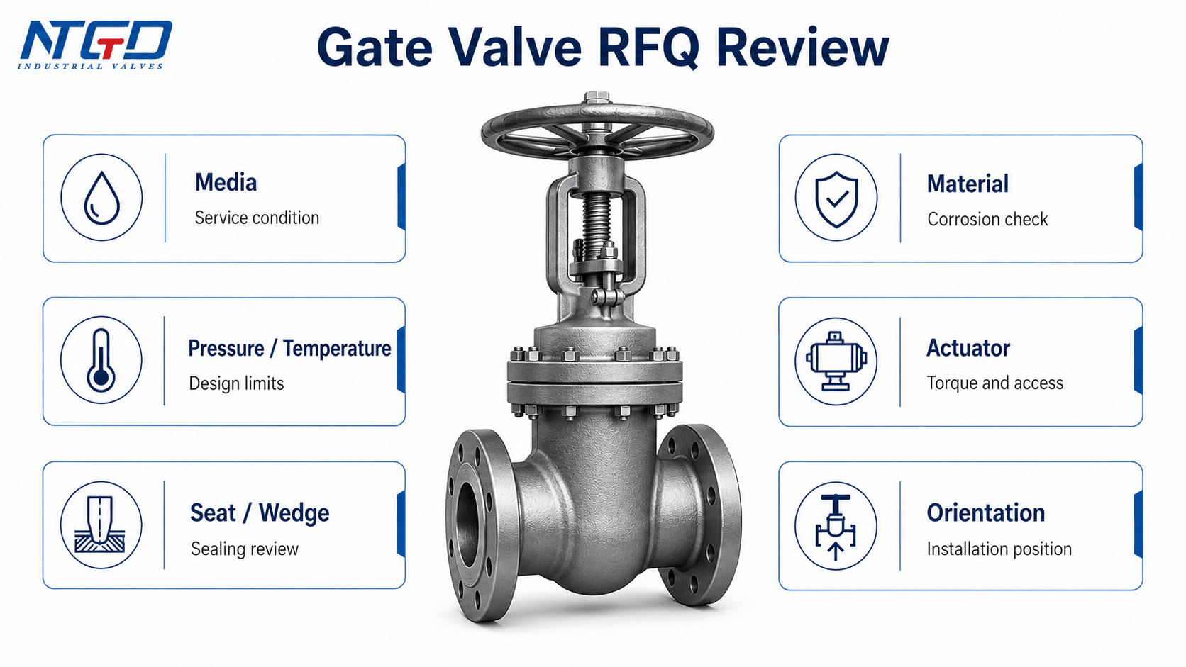
What to Confirm Before Sending a Gate Valve RFQ
Gate valve flow direction and installation orientation are not only installation questions. They also affect selection and specification. If the application requires bidirectional isolation, special orientation, actuator mounting, buried service, high-pressure service or severe media, this should be included in the RFQ.
A clear RFQ helps the manufacturer confirm whether a standard gate valve is suitable or whether a specific design, seat arrangement, actuator package or documentation requirement is needed.
| Пункт RFQ | Why it is needed | Example input |
|---|---|---|
| СМИ | Affects material, seat, trim and corrosion review | Water, steam, oil, gas, wastewater, corrosive media |
| Давление и температура | Affects body rating, seat design and sealing behavior | Class 150, PN16, high-temperature steam |
| Тип клапана | Confirms whether it is a gate valve, knife gate valve or another valve | Wedge gate valve, resilient seated gate valve |
| Требование к направлению потока | Confirms bidirectional or preferred pressure-side service | Bidirectional isolation required |
| Ориентация при установке | Confirms stem, handwheel, gearbox or actuator position | Horizontal line, stem-up preferred |
| Seat and wedge design | Affects sealing and direction review | Metal seated, resilient seated, solid wedge, flexible wedge |
| Материал | Affects corrosion and service life | WCB, CF8, CF8M, ductile iron |
| Концевое соединение | Affects installation and drawing review | Flanged, threaded, butt weld, socket weld |
| Actuator / gearbox | Affects torque, orientation and access | Manual handwheel, gear operator, electric actuator |
| Drawing and IOM need | Supports installation and commissioning | GA drawing, datasheet, installation manual |
For service-driven material questions in the RFQ, review Выбор материала задвижки together with the pressure, temperature, media and seat design.
Service conditions that affect direction and orientation review
Service conditions such as steam, high temperature, dirty water, wastewater, corrosive media, high pressure, buried installation or automated operation can make direction and orientation review more important.
For example, a small manual gate valve in a clean water line may require only basic checks. A large actuated gate valve in high-pressure service needs more detailed review of pressure side, actuator orientation, support, torque and documentation.
Valve design details to include in the request
When sending a gate valve inquiry, include the required valve type, pressure class, material, seat design, end connection, actuator type and installation position. If the valve must seal from both directions, say so clearly.
Do not rely on the word “gate valve” alone. The more specific the request, the easier it is to confirm whether the selected valve design is suitable.
Drawings, datasheets and IOM requirements
For project installation, request a datasheet, general arrangement drawing and IOM. These documents help confirm flow direction, body marking, installation orientation, actuator position and maintenance access before the valve reaches the site.
When service conditions or valve design details make the direction or orientation unclear, providing these RFQ details allows NTGD Valve’s engineering team to review bidirectional suitability, pressure-side requirements, actuator arrangement and installation orientation before procurement.
ЧАСТО ЗАДАВАЕМЫЕ ВОПРОСЫ
Do gate valves have a flow direction?
Most standard gate valves do not have a fixed flow direction in ordinary isolation service. However, the actual valve should still be checked for body arrows, seat design, pressure-side requirements and manufacturer IOM instructions.
Are gate valves bidirectional?
Many standard industrial gate valves are bidirectional in on-off isolation service. This should not be automatically applied to knife gate valves, which may be unidirectional or require specific seat-side verification.
Does it matter which way a gate valve is installed?
Yes. Even if flow can pass from either direction, the valve may still have a required body-arrow direction, preferred pressure side, stem orientation, actuator position or maintenance-access requirement.
What does the arrow on a gate valve body mean?
A body arrow may indicate recommended flow direction, preferred pressure direction or a manufacturer-specific installation reference. It should be interpreted using the valve IOM, datasheet or drawing, not by assumption.
Can a gate valve be installed backwards?
First identify whether “backwards” refers to flow direction, body arrow, stem orientation, wrong valve type or handwheel operation. Then check the IOM, body marking, datasheet and project drawing before correction.
Can gate valves be installed upside down?
Some orientations may be allowed by design, but upside-down or stem-down installation can create risks for debris accumulation, packing behavior, access and maintenance. The manufacturer’s IOM should be checked before approving this orientation.
Can a gate valve be installed horizontally?
A gate valve may be installed horizontally if the valve design, support, clearance and manufacturer instructions allow it. Large, heavy or actuated gate valves need closer review because weight, torque and actuator access can affect long-term operation.
Is gate valve flow direction the same as globe valve flow direction?
No. Gate valves and globe valves have different internal structures. A standard gate valve is often bidirectional, while many globe valves have a preferred or required flow direction based on their plug and seat arrangement.
When the question is specifically about a globe valve, use the dedicated globe valve flow direction guide instead of applying this gate-valve rule.
Is a gate valve the same as a check valve for flow direction?
No. A gate valve is an isolation valve. A check valve is a one-way valve designed to prevent reverse flow. A check valve flow arrow normally indicates required flow direction, while a gate valve may require a more design-specific review.
Which direction do you turn a gate valve to close?
Many manual gate valves close by turning the handwheel clockwise, but this should be confirmed by the handwheel marking, gearbox or manufacturer instruction. Handwheel operating direction is not the same as pipeline flow direction.
Заключение
Gate valve flow direction should be judged with both general valve theory and project-specific verification. Many standard industrial gate valves are bidirectional in normal isolation service because the gate moves perpendicular to a straight-through flow path. But direction still matters when a valve has a body arrow, special seat or wedge design, preferred pressure side, actuator package, large-size configuration or manufacturer-specific installation requirement.
For safe installation, do not treat flow direction, body arrow, installation orientation and handwheel operating direction as the same thing. Check the valve type, body marking, datasheet, drawing and IOM before installation. For critical service, confirm bidirectional sealing, orientation, actuator access and pressure-side requirements before procurement.
For gate valve selection or RFQ review, provide the service media, pressure, temperature, size, pressure class, material, end connection, seat or wedge design, actuator type and installation orientation. This information helps confirm whether a standard gate valve is suitable or whether a special design review is required.
The safest decision hierarchy is: first follow the manufacturer’s IOM, then confirm body markings and nameplate data, then review the specific valve design and service condition, and only then apply general gate valve rules. This hierarchy reduces installation risk more effectively than relying on a single statement that gate valves are bidirectional.
