
Быстрый ответ
Четыре основные отрасли промышленности Типы концевых соединений шаровых кранов — фланцевые, резьбовые, с приварной муфтой и для стыковой сварки. Здесь, Типы соединений шаровых кранов имеет в виду именно соединения между клапаном и трубопроводом — а не конструкцию корпуса, конструкцию портов, опору шарика или механизм привода.
В фланцевых соединениях используются соприкасающиеся поверхности фланцев, прокладка и болтовое соединение. В резьбовых соединениях используются совместимые наружная и внутренняя резьба с необходимым способом уплотнения. В соединениях с муфтовой сваркой труба вставляется в углубленную муфту перед внешней сваркой, тогда как в соединениях со стыковой сваркой подготовленные концы клапана и трубы выравниваются непосредственно перед сваркой.
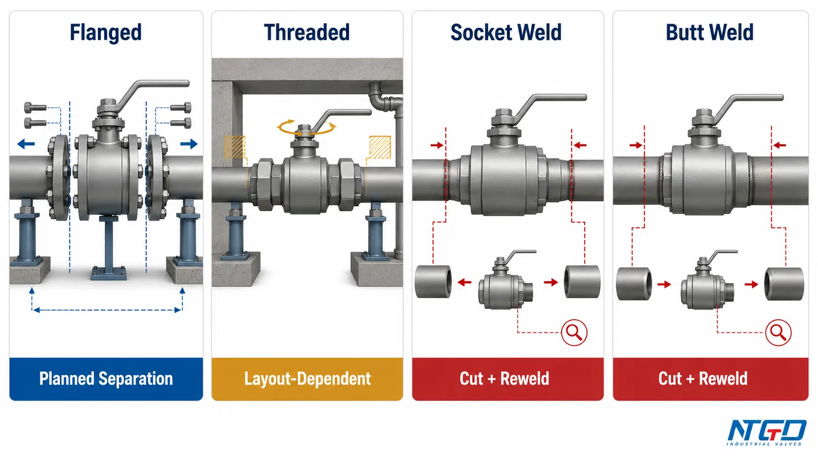
Фланцевые и резьбовые соединения могут допускать плановый демонтаж, хотя фактическая возможность демонтажа зависит от опор трубопровода, зазоров, степени коррозии, точек изоляции и конфигурации трубопровода. Соединения с приваркой в паз и встык, как правило, образуют постоянные соединения трубопровода и обычно требуют резки и дополнительных работ для полного демонтажа клапана.
Не существует универсально оптимального варианта соединения. При выборе необходимо учитывать интерфейс трубопровода, давление и температуру, рабочую среду, стратегию технического обслуживания, применимые стандарты, внешние нагрузки и доступные конструкции клапанов. Фактический способ демонтажа напрямую влияет на планирование остановки, стратегию использования запасных клапанов, а также на то, следует ли в запросе предложений указать зазор для разъединения фланцев, соединительную муфту, съемный золотник или план замены сваркой.
Шаровой кран с пластинчатым узором рассматривается отдельно, поскольку представляет собой специальную конструкцию с фланцевым креплением, а не пятый тип параллельной заделки конца трубы.
Выбор типа торцевого соединения влияет не только на способ крепления клапана к трубопроводу. Тип соединения определяет, где может возникнуть путь внешней утечки, какие меры контроля при монтаже необходимо принять, как можно демонтировать клапан и какая информация должна быть указана в техническом задании на закупку.
Два клапана могут иметь одинаковый шарик, седла, материал корпуса и привод, но при этом различаться по типам трубных соединений. И наоборот, два клапана с одинаковым типом трубного соединения могут отличаться конструкцией корпуса, схемой проходов, предельными значениями давления и температуры или системой седел. Таким образом, выбор типа трубного соединения является лишь одной из составляющих полной спецификации клапана, а не заменяет её.
В данном руководстве определены границы классификации, проведено сравнение четырёх основных типов соединений, а также приведены рекомендации по выбору исходного варианта с учётом типичных условий проекта. Окончательная пригодность должна проверяться с учётом технических условий проекта, требований к соединениям, утверждённых чертежей производителя и полного технического паспорта клапана.
Какие бывают типы торцевых соединений шаровых кранов?
Торцевое соединение шарового крана представляет собой соединительный узел, связывающий рабочую камеру крана с прилегающим трубопроводом. Оно определяет, как кран и труба соединяются друг с другом, где находится уплотнение в месте соединения, что обеспечивает прочность соединения, а также как впоследствии можно демонтировать или заменить кран.
В этом руководстве, Типы соединений шаровых кранов означает соединения концов труб между промышленным шаровым краном и трубопроводной системой. Это не относится ко всем классификациям, используемым для описания шарового крана.
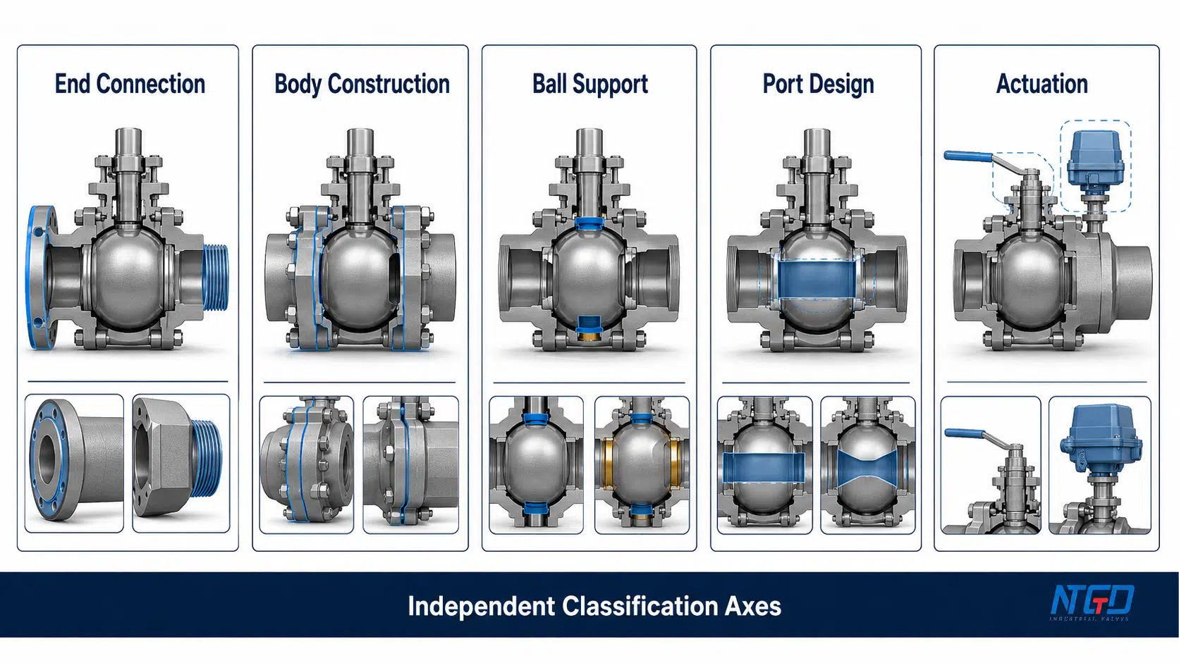
Соединение «конец» и корпус, порт, опора шарика и привод
В описаниях продукции часто смешиваются несколько осей классификации. Разделение этих осей позволяет избежать того, чтобы руководство по выбору концевых соединений превратилось в неточный перечень несвязанных между собой типов шаровых кранов.
| Ось классификации | Что она описывает | Примеры |
|---|---|---|
| Концевое соединение | Как клапан соединяется с трубопроводом | С фланцем, с резьбой, для сварки в гнездо, для стыковой сварки |
| Конструкция кузова | Как собирается корпус под давлением | Однокомпонентный, двухкомпонентный, трехкомпонентный |
| Опора шарика | Как шарик удерживается внутри | Плавающая, на цапфовом креплении |
| Дизайн порта | Форма и площадь проходного канала | Полное сечение, суженное сечение, V-образное сечение |
| Приведение в действие | Как создается рабочий крутящий момент | Ручной, пневматический, электрический |
Трехкомпонентный шаровой кран может поставляться с резьбовыми, приварочными (с втулкой) или стыковыми приварными концами. Шаровой кран с поворотным валом может иметь фланцевое или приварочное соединение. Ни одна из этих классификаций корпуса или внутренних элементов не определяет тип соединения с трубой.
Это различие также имеет значение с точки зрения технического обслуживания. Корпус, состоящий из трёх частей, может обеспечивать доступ к внутренним компонентам при наличии соответствующих условий, однако сварные концы труб всё равно могут препятствовать демонтажу клапана целиком без разрезания трубопровода. Возможность технического обслуживания корпуса и возможность демонтажа клапана из трубопровода связаны между собой, но не являются одним и тем же свойством.
Запрос на предложение, в котором указаны только такие характеристики, как “трехкомпонентный”, “с полным проходом” или “с цапфовым креплением”, считается неполным. Без отдельной спецификации торцевых соединений поставляемый клапан может оказаться несовместимым с трубопроводами на объекте, даже если все остальные характеристики изделия указаны верно.
Читатели, которым требуется более обширная таксономия дизайна, могут ознакомиться с Основные типы шаровых кранов и руководство по выбору, которая позволяет выделить такие категории конструкций, как плавающие, установленные на цапфах, портовые, входящие в корпус и другие, в отличие от соединений с торцевыми трубами.
Стандартные соединения концов труб и специальные схемы монтажа
При подборе промышленных шаровых кранов выделяют четыре основные группы концов трубопроводов:
- Фланцевые концевые соединения;
- Резьбовые концевые соединения;
- Соединения с приварными муфтами;
- Торцевые соединения с наварной сваркой.
В специализированных системах могут применяться и другие схемы монтажа, однако их не следует автоматически рассматривать как равноправные элементы данной базовой классификации. Например, шаровой кран с пластинчатым уплотнением устанавливается между фланцами трубопровода и крепится с помощью системы болтовых соединений, монтируемой на фланцах. Этот вариант будет рассмотрен далее в разделе, посвященном специальным схемам монтажа.
Те же границы сферы применения распространяются на санитарные, рифленые, разъемные и другие интерфейсы, предназначенные для конкретных задач. Их наличие не означает, что руководство по торцевым соединениям промышленных шаровых кранов должно превращаться в энциклопедию всех возможных видов трубопроводных соединений.
Четыре основных типа концевых соединений шаровых кранов
В приведенной ниже таблице представлено сравнение четырёх групп соединений на уровне установленного соединения. В ней не указаны универсальные предельные значения размера, давления или температуры. Эти предельные значения зависят от общей конструкции клапана, материалов, системы седла, требований к соединению и документации производителя.
| Тип соединения | Совместный механизм | Основной интерфейс внешнего уплотнения | Инструкция по удалению | Управление основной установкой | Последствия технического обслуживания | Типичное начальное направление | Главное предостережение |
|---|---|---|---|---|---|---|---|
| Фланцевый | Соединительный клапан и фланцы труб, закрепленные болтами | Прокладка или предусмотренная система уплотнения торца фланца | Возможен плановый демонтаж | Совместимость, центрирование, состояние прокладок и контролируемое затягивание болтов | Удаление возможно после изоляции, обеспечения опоры и надлежащего разъединения фланцев | Стандартизированные технологические трубопроводы и доступ для планового технического обслуживания | Несоосность или неравномерная нагрузка могут привести к снижению нагрузки на прокладку и увеличению напряжений в трубопроводе |
| Резьба | Совместимые наружная и внутренняя резьбы соединены | Соединение с помощью резьбы и/или установленный уплотнительный элемент | Возможно удалить, но это зависит от макета | Форма резьбы, зацепление, крутящий момент, чистота и способ уплотнения | Для демонтажа может потребоваться поворот, разъединение соединения, снятие заглушки или перемещение трубы | Компактные трубопроводы и соответствующие резьбовые соединения оборудования | Несоответствие размеров, задир, чрезмерная затяжка или недостаточный зазор могут помешать установке уплотнения или его последующему снятию |
| Сварка в паз | Труба вводится в утопленное гнездо клапана и приваривается снаружи | Готовое соединение с приваркой в муфту | Как правило, требуется резка или доработка сварных швов | Установка, условия вставки, контроль температуры и качество сварки | Полное демонтаж, как правило, влечет за собой выполнение работ по резке, повторной сварке и повторной проверке | Компактные сварные трубопроводы, изготовленные по проекту | В связи с температурными режимами и геометрией гнезда может потребоваться проверка седла, возможности очистки и коррозионной стойкости |
| Сварка встык | Подготовленные клапаны и концы труб совмещаются встык и свариваются | Готовое стыковое сварное соединение | Обычно требуется разрезка и повторная сварка | Требования к подготовке торцов, осевому выравниванию, сварке и контролю качества | Для замены необходима продуманная стратегия резки, ремонта и осмотра | Непрерывносварные трубопроводы, изготовленные по спецификации проекта | Целостность зависит от подготовки, выравнивания, сварки, контроля и эксплуатационных нагрузок |
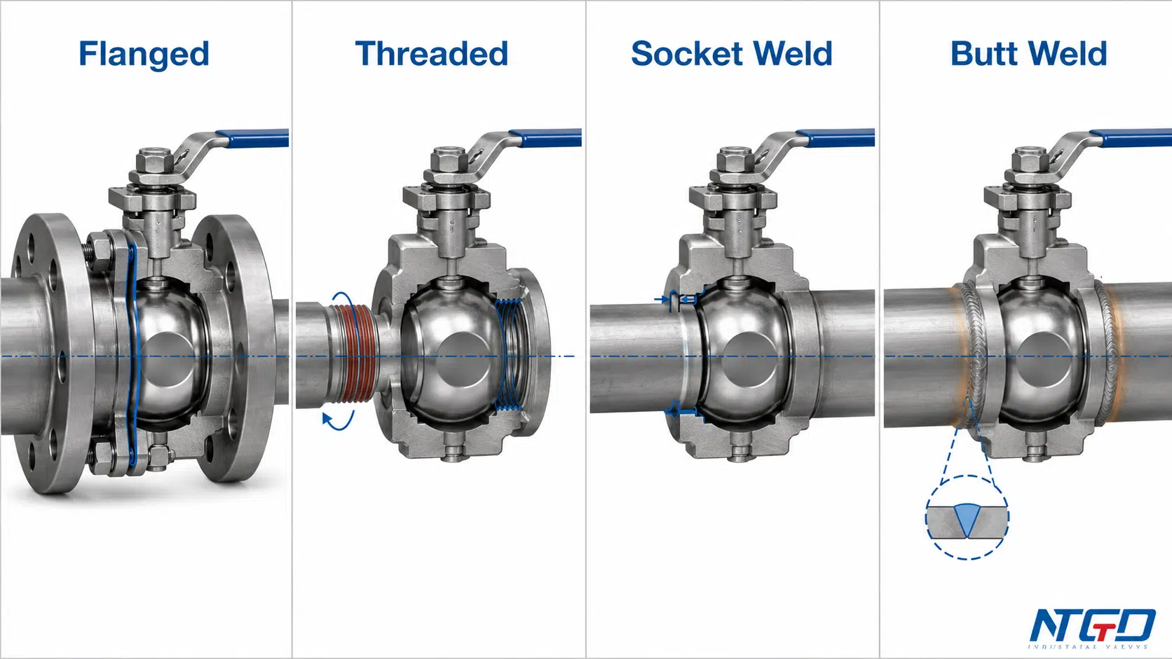
Корпус клапана может быть аналогичным, но тип соединения может обусловливать совершенно разные подходы к отключению и резервированию. Механически разъемное соединение может потребовать большего монтажного пространства и дополнительных крепежных элементов, в то время как сварное соединение позволяет сократить количество разъемных интерфейсов, но при этом полная замена клапана будет зависеть от проведения работ по резке, сварке и повторной проверке на месте эксплуатации.
Фланцевые соединения
Шарнирный клапан с фланцами имеет встроенные или указанные в технических условиях фланцевые концы, которые соединяются с соответствующими фланцами трубопровода. Установленное соединение фиксируется болтами, а внешнее уплотнение образуется на соприкасающихся поверхностях с помощью указанной прокладки или уплотнительной системы.
Соединение следует рассматривать как единую систему, а не как два металлических диска, соединенных между собой. Совместимость включает в себя требования к фланцам, номинальный размер, обозначение давления, поверхность прилегания, прокладку, схему расположения болтов, материал болтов и монтажную зону.
Чтобы ознакомиться с доступными вариантами конструкции фланцев, материалами и проверить технические характеристики конкретных изделий, ознакомьтесь с Страница продукта «шаровой кран с фланцами».
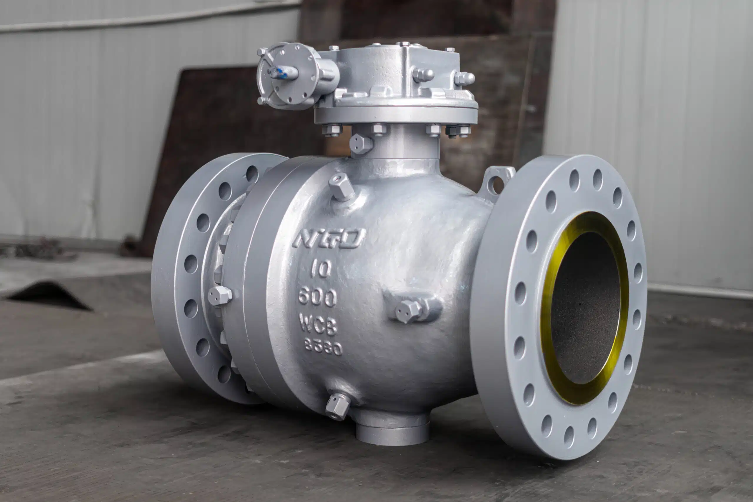
Фланцевые соединения обычно рассматриваются в тех случаях, когда в трубопроводной системе уже используются стандартизированные фланцевые соединения или когда важна возможность последующего демонтажа клапана. Они позволяют отсоединить клапан от трубопровода без разрезания его концов, находящихся под давлением, однако для демонтажа по-прежнему требуется:
- Безопасная изоляция и сброс давления;
- Опора для клапана и прилегающих трубопроводов;
- Доступ для снятия болтов;
- Расстояние между фланцами должно быть достаточным для извлечения клапана;
- Проверка или замена прокладки;
- Контролируемое выравнивание и повторная сборка.
Подробные рекомендации по выравниванию, прокладкам, затяжке болтов, монтажу, демонтажу и техническому обслуживанию приведены в Руководство по монтажу и техническому обслуживанию шарового крана с фланцевым соединением.
Неправильное расположение труб нельзя исправлять путем сближения фланцев с помощью болтов. Такой подход может привести к неравномерной нагрузке на прокладку, передаче внешних нагрузок на корпус клапана и образованию пути утечки, которого можно было бы избежать.
Выравнивание и независимая опора приобретают особое значение в тех случаях, когда вес клапана или привода, тепловые деформации, повышенные нагрузки на фланцы или значительные нагрузки со стороны внешних трубопроводов приводят к увеличению сил, действующих на соединение. Трубопровод должен обеспечивать опору для установленной системы, а не использовать клапан в качестве устройства для выравнивания.
Резьбовые концевые соединения
Штоковые шаровые краны подключаются непосредственно к совместимым резьбовым концам труб или патрубкам оборудования. В зависимости от конструкции кран может иметь внутреннюю, наружную или смешанную резьбу на концах.
“Само по себе понятие ”резьба» не является полной спецификацией соединения. Покупатель должен указать семейство резьбы, номинальный размер, тип резьбы (наружная или внутренняя), форму (коническую или параллельную), а также предполагаемый способ уплотнения. Резьбы, которые на первый взгляд кажутся совместимыми, могут оказаться несовместимыми по шагу, профилю, конусности или принципу уплотнения.
Таким образом, обозначения NPT, BSPT и BSPP не являются взаимозаменяемыми. Коническая и параллельная резьба используют разные схемы зацепления и уплотнения. В запросе на предложение (RFQ) необходимо указать резьбу клапана в соответствии с сопрягаемым элементом трубопровода и требованиями проекта, а не ограничиваться общим описанием “резьбовой концевой части”.
Для соединений типа NPT Стандарт ASME B1.20.1 на трубную резьбу содержит справочные данные по размерам резьбы и контрольно-измерительным приборам; резьбы BSPT и BSPP должны указываться в соответствии с применимыми к ним требованиями, а не рассматриваться как эквиваленты резьбы NPT.
Резьбовые соединения часто выбирают для компактных установок и при подборе оборудования с резьбовыми патрубками. Их меньшие габариты могут оказаться полезными в тех случаях, когда нет места для фланцевого соединения. Качество монтажа по-прежнему зависит от:
- Правильная совместимость резьбы;
- Чистая и неповреждённая резьба;
- Достаточная вовлеченность;
- Регулируемый момент затяжки при сборке;
- Метод уплотнения, совместимый с соединением и рабочей средой;
- Не допускать чрезмерной крутильной нагрузки на корпус клапана.
Наличие резьбы не всегда означает, что деталь легко снять. Если клапан застрял между жесткими трубами с резьбой и не может поворачиваться, а съемное соединение не предусмотрено, может потребоваться повреждение труб или их разрезание.
Engineers should establish the isolation points, rotation clearance, and removal path during piping-layout development. The result often determines whether the RFQ must include a union, removable spool, or another deliberate separation point.
Соединения с наварными муфтами
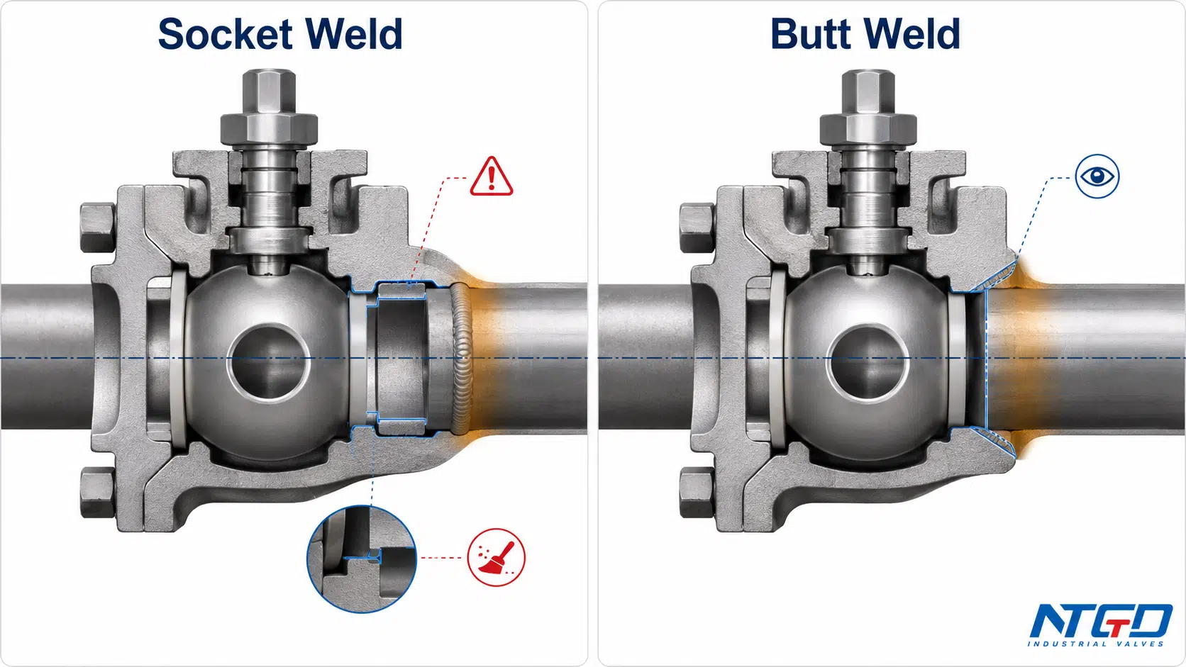
A socket weld ball valve has a recessed socket in each valve end. The pipe enters the socket and an external weld completes the joint.
The socket assists initial positioning, but joint quality still depends on fit-up, heat control, material compatibility, welding quality, and any project-required inspection. The connection removes a threaded pipe joint, but it does not create an automatically leak-free or maintenance-free installation.
Welding heat can travel toward the body, seats, seals, and body joints. When soft seats are close to the weld zone, the manufacturer’s installation limits and heat-control requirements must be established before site work begins.
The socket recess also creates an internal geometry that may matter in services sensitive to crevice corrosion, retained product, solids, or process cleanliness. Where these risks or future replacement difficulties are significant, socket weld suitability should be confirmed against the specific valve design and maintenance plan.
For product-specific socket dimensions, ratings, body configurations, installation limits, and replacement checks, use the dedicated socket weld ball valve selection guide.
Торцевые соединения с стыковой сваркой
Butt weld ball valves have prepared ends that align directly with prepared pipe ends. The valve and pipe ends are then joined through the project-defined butt-weld arrangement.
Unlike socket weld, the pipe does not terminate inside a recessed valve socket. The valve and pipe ends must be compatible in diameter, wall condition, end preparation, material, and alignment. Joint quality depends on the approved welding and inspection requirements for the project.
Butt weld ends are commonly considered where the piping design requires a continuous welded arrangement. They may reduce detachable mechanical joints, but external loading, thermal effects, inspection access, repair strategy, and material compatibility remain part of the installed design.
A butt weld connection should not be selected solely because the service is described as high pressure or critical. The end form must follow the piping design basis and complete valve specification. The manufacturer must confirm the valve-end preparation, wall transition, material, rating, and construction against the project requirements.
Complete valve removal usually requires cutting the line and performing new welding and inspection. Shutdown time, support, replacement length, access, and field-repair capability must be planned before the connection is specified.
Шаровые краны с фланцевым и резьбовым соединением: как выбрать подходящий тип соединения
The essential difference is the installed joint.
A flanged ball valve uses matching flange faces, bolting, and a gasket or specified flange seal. A threaded ball valve uses compatible male and female threads with the sealing method required by that thread design.
Flanged connections generally provide a clearer planned-disassembly path. Threaded connections generally provide a smaller installed envelope. Neither statement is absolute. A flanged valve may remain difficult to remove without support and separation space, while a threaded valve may be impossible to rotate out of a rigid piping run.
| Коэффициент сравнения | Фланцевый шаровой кран | Threaded Ball Valve |
|---|---|---|
| Joint mechanism | Bolted mating flanges | Engaged male and female threads |
| External sealing interface | Gasket or specified flange-face sealing arrangement | Thread engagement and/or specified independent sealing element |
| Required connection data | Flange requirement, size, pressure designation, facing, gasket and bolting basis | Thread family, size, tapered or parallel form, male/female arrangement and sealing method |
| Installed envelope | Larger because of flange faces and bolting | Usually more compact after installation |
| Installation control | Alignment and gasket loading must be controlled; forcing misaligned flanges together can create joint leakage and body load | Compatibility and assembly torque must be controlled; mismatch or overtightening can damage the joint before service begins |
| Removal reality | Provides a defined separation plane, but only when isolation, support, bolt access and flange separation are available | Mechanical removal depends on rotation space and a planned union or spool; otherwise field pipe work may still be required |
| Доступ для технического обслуживания | Often easier to plan into process piping | Convenient only when the piping arrangement supports disassembly |
| External-load concern | Flange misalignment, bolt loading and pipe bending | Torsional assembly load, thread stress and pipe restraint |
| Vibration review | Requires review of support, bolting, gasket behavior and cyclic loading | Requires review of engagement, support, sealing system and cyclic loading |
| Damage concern | Flange-face damage, gasket damage or uneven loading | Cross-threading, overtightening, galling or damaged threads |
| Upfront cost direction | Usually requires more connection hardware, space and assembly work | Often uses fewer separate joint components |
| Lifecycle implication | Planned gasket and bolting renewal can make future disassembly more predictable when clearance is provided | Reuse and replacement become less predictable if threads seize, gall or cannot be rotated out of the piping |
| Typical initial direction | Standardized process piping and planned periodic removal | Compact piping with a confirmed threaded interface |
| Необходимо проверить | Approved flange configuration, complete valve datasheet, alignment and removal clearance | Exact thread specification, complete valve datasheet, sealing method and removal path |
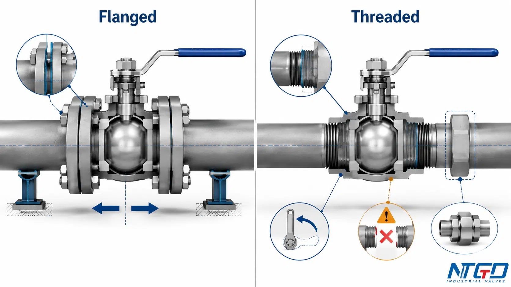
Соединение с болтами и прокладками по сравнению с сопряженными трубными резьбами
Flanged and threaded connections place the external sealing function in different locations.
In a flange joint, bolting creates the load needed to compress the gasket or specified seal between the mating faces. Installed integrity depends on the condition and compatibility of the flange faces, gasket, bolting, alignment, and applied load.
In a threaded joint, the sealing mechanism depends on the thread design. Some connections use tapered engagement with a compatible sealing compound or tape; parallel-thread arrangements commonly depend on a separate sealing feature. A connection may engage mechanically and still fail to provide the intended seal.
Установочное пространство, центрирование и совместимость резьбы
A threaded valve normally occupies less space after installation, but the installer may need enough room to rotate the valve or adjacent pipe. A compact final envelope does not guarantee a compact assembly or removal procedure.
A flanged valve requires room for flange hardware, bolt access, support, and later flange separation. The piping must align without using the flange bolts to force the valve into the gap.
The decision should account for both:
- Operating envelope: the space occupied after installation;
- Installation and maintenance envelope: the space needed to assemble, rotate, separate, remove, and reinstall the valve.
Демонтаж и техническое обслуживание — это не одно и то же
Flanged valves are often selected where planned removal is expected because routine removal does not require cutting the valve ends. The piping must still be isolated, depressurized, supported, and separated safely.
Threaded valves can be removed without cutting only when the layout permits rotation or includes a union, disconnect, or removable spool. A valve trapped between two rigid threaded pipe ends may be less maintainable than its compact shape suggests.
Material and condition also affect removal. Stainless-steel threaded joints may require controlled assembly practices to manage galling. Corrosion, damaged threads, excessive sealing material, or previous overtightening can prevent reliable reuse.
Когда каждое соединение обычно рассматривается
A flanged connection may be an initial direction when:
- The piping system already uses matching flanges;
- Periodic complete removal is expected;
- A standardized gasketed and bolted interface is required;
- Valve or actuator weight calls for a planned supported installation;
- Future replacement should avoid cutting the pipe ends.
A threaded connection may be an initial direction when:
- The mating pipe or equipment has the specified thread;
- Installed space is limited;
- The layout permits controlled assembly and future removal;
- The valve is available with the exact required thread;
- The project permits a threaded joint for the service.
Neither connection should be selected through a universal pressure or pipe-size rule. The verified complete-valve rating and the completed installed joint always override generalizations attached to a connection family.
Шаровые краны с муфтовой сваркой и сваркой встык: основные технические различия
Socket weld and butt weld ball valves both form welded pipe joints, but the joint geometry and field controls differ.
A socket weld joint inserts the pipe into a recessed valve-end socket before external welding. A butt weld joint aligns prepared valve and pipe ends directly before welding.
| Engineering Point | Сварка в паз | Сварка встык |
|---|---|---|
| Joint geometry | Pipe inserted into a recessed socket | Prepared ends aligned end-to-end |
| Weld arrangement | External socket weld | Butt or groove weld defined by the project |
| Fit-up focus | Pipe insertion, socket condition, specified allowance and orientation | End preparation, wall compatibility and axial alignment |
| Внутренняя геометрия | Socket transition may create an internal discontinuity | Can provide a more continuous transition when correctly matched and aligned |
| Heat concern | Heat transfer toward the valve body and soft parts | Heat transfer across the end-to-end weld zone |
| Cleanability concern | Socket recess may require review for crevice or retention risks | Internal mismatch or weld condition requires review |
| Инспекция | Defined by the project, material and joint requirements | Defined by the project, material and joint requirements |
| Removal | Usually requires cutting and welded rework | Usually requires cutting and welded rework |
| Typical initial direction | Компактные сварные трубопроводы, изготовленные по проекту | Непрерывносварные трубопроводы, изготовленные по спецификации проекта |
| Основное предупреждение | Socket geometry does not remove heat, cleanliness or maintenance constraints | A butt weld end does not make the complete valve automatically suitable for critical service |
Подготовка к вставке муфты и наружному сварному соединению по сравнению с подготовкой к сварке «встык»
The socket provides a physical recess for pipe insertion, but dimensional and procedural control remain necessary. The valve end, pipe outside diameter, insertion condition, orientation, and approved installation method must be compatible.
Butt weld ends require direct matching of valve and pipe preparations. Mismatch in end geometry, wall transition, or alignment can complicate welding, inspection, and internal flow continuity.
These checks belong before delivery to site. Discovering an incompatible end preparation after the piping has been positioned can require a transition piece, replacement valve, or field modification.
Вопросы, связанные с нагревом, монтажом, проверкой и возможностью очистки
Welding heat can affect seats, seals, body joints, coatings, and adjacent components. The actual risk depends on the valve design, material, wall section, welding process, sequence, cooling method, and manufacturer instructions.
For a soft-seated valve, the connection choice must be reviewed together with the distance between the weld zone and temperature-sensitive components. A workable welded-end design is one for which the manufacturer has defined installation limits and the site can realistically follow them.
Socket weld geometry also deserves added review when the service is sensitive to crevice corrosion, retained material, solids, or process cleanliness. Butt weld geometry requires close control of alignment, wall transition, root condition, and inspection access.
TWI’s socket-weld technical overview illustrates the recessed-socket geometry and explains why the internal recess and required gap can create retention and cleanability concerns.
This guide does not define a welding procedure. Qualification, inspection method, acceptance criteria, and post-weld requirements belong to the project engineering and quality system.
Демонтаж, ремонт и последствия для жизненного цикла
Both welded end forms shift maintenance effort from mechanical disassembly to cutting, preparation, rewelding, and reinspection.
A three-piece ball valve may allow internal servicing while the end pieces remain in the line, but this does not make the complete welded valve removable. The maintenance plan should distinguish:
- Servicing internal parts with the ends left in the piping;
- Removing the complete pressure-containing assembly;
- Repairing a damaged welded end;
- Re-establishing and reinspecting the piping joint.
Where rapid replacement matters, welded-end serviceability should be evaluated before the end connection is selected.
Как правильно выбрать тип присоединения для шарового крана
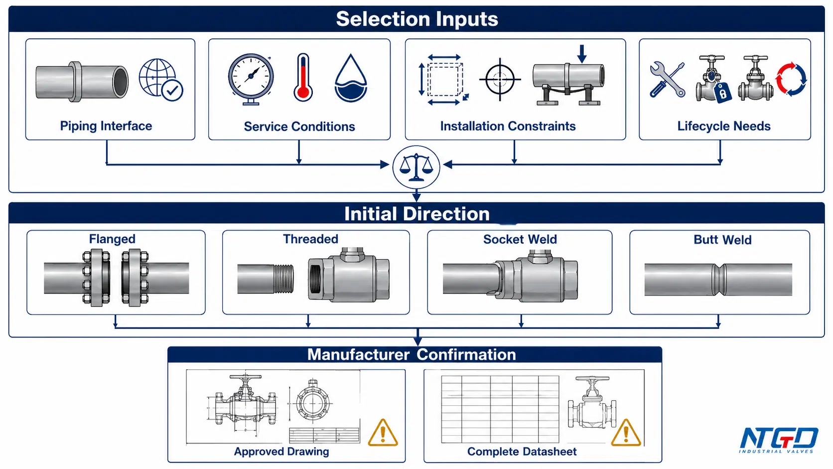
A useful selection process does not begin with “Which connection is strongest?” It begins with the piping system, operating conditions, maintenance plan, and specified interface.
Доступные размеры клапанов и соответствующие соединения трубопроводов
First confirm that the required valve design is available with an end connection matching the piping system.
Проверьте:
- Nominal valve and pipe size;
- Pipe schedule or end geometry where relevant;
- Existing flange, thread, socket, or weld-end requirement;
- Available valve body construction;
- Face-to-face or end-to-end space;
- Required transition between valve and piping.
A theoretically preferred connection has little value if it is unavailable with the required body construction, material, bore, seat design, or actuator arrangement.
Ignoring the actual interface can turn a simple valve installation into a field transition-spool, adapter, or replacement-valve problem. Product availability, piping requirements, maintenance, and project standards must take priority over universal size rules.
Расчетное давление, температура и совместимость с рабочей средой
The end connection contributes to installed-joint suitability but does not define the complete valve pressure-temperature capability.
Проверьте:
- Design and operating pressure;
- Design and operating temperature;
- Pressure and temperature cycles;
- Fluid composition and phase;
- Corrosion, erosion, solids, or contamination;
- Hazard and leakage consequence;
- Body material;
- Seat, seal, and packing materials;
- Joint components and sealing materials.
For flanged joints, gasket and bolting suitability matter. For threaded joints, the exact thread and sealing arrangement matter. For welded joints, pipe and valve-end material compatibility, heat effects, and project welding requirements matter.
A joint may satisfy its connection requirement while the complete valve remains unsuitable because of its seat, packing, body material, construction, or temperature limit. Connection verification and complete-valve verification must therefore be completed together.
Место для установки и доступ для технического обслуживания
Selection must account for both installation and future maintenance.
For flanged ends, review:
- Bolt access;
- Valve lifting and support;
- Flange-separation space;
- Gasket replacement access;
- Adjacent equipment and insulation;
- Actuator clearance.
For threaded ends, review:
- Rotation clearance;
- Wrench access;
- Whether the valve or pipe can rotate;
- Availability of a union or removable spool;
- Risk of thread seizure or damage.
For welded ends, review:
- Welding and inspection access;
- Heat-control requirements;
- Cutting and replacement space;
- Shutdown and field-repair capability.
A valve that fits the operating space may still be impossible to remove within the available shutdown window. Maintenance access must be treated as a design input, not an assumption left for the site team.
Broader checks for Cv, port size, pressure drop, installation space, connection fit, and final testing are covered in the Руководство по подбору размеров и монтажу шаровых кранов.
Вибрация, нагрузки на трубопроводы и выравнивание
No connection family determines vibration performance by name alone.
Обзор:
- Pipe support locations;
- Valve and actuator weight;
- Thermal movement;
- Cyclic bending;
- Installation misalignment;
- Pump- or compressor-induced vibration;
- Water hammer or other transient loads;
- External nozzle loads;
- Maintenance-induced pipe movement.
A flange joint may lose uniform gasket loading or experience bolt relaxation. A threaded joint may be exposed to torsional stress, loosening, or fatigue near the engaged section. A welded joint may transfer external loading directly into the valve end and body.
Ignoring these loads can produce recurring end-joint leakage, fatigue damage, loosened hardware, or an installation that cannot maintain alignment. The connection must be reviewed as part of the supported piping system.
Применимые стандарты, стратегия проведения проверок и замены
Connection compatibility should be stated explicitly in the specification.
Depending on the end form, the RFQ may need to identify:
- Flange requirement and facing;
- Pressure designation;
- Thread family and male/female arrangement;
- Tapered or parallel thread;
- Socket weld interface;
- Butt weld end preparation;
- Material and wall compatibility;
- Required inspection;
- Manufacturer drawing approval.
An incomplete standard or inspection requirement may not be discovered until the valve reaches the site or enters project document review. The result can be rejected drawings, incompatible mating ends, added transition work, or delayed acceptance.
Replacement strategy also matters. A connection efficient during initial construction may be expensive to remove during an unplanned shutdown, while a connection selected for maintainability may require more space and hardware from the outset.
От исходных условий проекта до подтверждённого выбора соединения
The matrix provides an initial direction, not a universal rule. The project specification, approved manufacturer drawing, and complete valve datasheet take priority over every general selection statement below.
| Состояние проекта | Начальное направление | Инженерное обоснование | Must Verify |
|---|---|---|---|
| Existing standardized flanged process piping | Фланцевый | Matches the established bolted and gasketed interface | Approved flange configuration and datasheet |
| Periodic complete valve removal is expected | Фланцевый | Provides a defined mechanical separation point | Support and flange-separation clearance |
| Compact line with a matching threaded equipment port | Резьба | Matches the equipment interface without separate flange hardware | Exact thread and removal path |
| Small-bore line with a project-approved threaded joint | Threaded may be considered | Uses an established compact project connection | Service suitability and support |
| Project requires socket weld piping ends | Сварка в паз | Matches the specified recessed welded interface | End detail and heat limits |
| Project requires a continuous end-to-end welded joint | Сварка встык | Matches the specified welded piping arrangement | Approved end preparation and inspection |
| Limited installed envelope | Threaded or wafer-pattern arrangement may be reviewed | A smaller installed envelope may help | Assembly space and product datasheet |
| High vibration or cyclic external loading | No automatic choice | Performance depends on support, fit-up and system dynamics | Piping-load review and manufacturer limits |
| Stainless-steel threaded joint | Threaded only after assembly review | Galling may affect installation and reuse | Material pairing and assembly method |
| Hazardous fluid or high leakage consequence | Project-specified connection after detailed review | The complete installed joint carries greater consequence | Code basis and completed-joint verification |
| Rapid future replacement is a priority | Flanged or deliberately removable threaded layout | A planned separation point can reduce field rework | Removal clearance and spare strategy |
| Long piping run with limited shutdown access | Compare welded and removable options by lifecycle requirement | Initial integrity and future repair effort must be balanced | Repair access and replacement plan |
Почему конечные соединения не определяют полные номинальные характеристики клапана
A complete rating check has at least four layers.
1. Предельное давление в клапане
This includes the body, body joints, stem retention, seats, packing, seals, and other pressure-containing features. The end connection does not determine these features by itself.
2. Требования к торцевому соединению
The flange, thread, socket, or butt weld end must match the specified piping interface. Compatibility includes geometry, material, rating basis, and dimensional requirements.
3. Монтажное соединение
The completed joint includes components and workmanship outside the valve:
- Flange gasket and bolting;
- Thread engagement and sealing material;
- Socket weld fit-up and completed weld;
- Butt weld preparation, alignment, completed weld, and inspection.
4. Условия оказания услуг по проекту
Design pressure and temperature are only part of the service. Cyclic loads, vibration, corrosion, fluid hazard, external piping loads, shutdown frequency, and maintenance access can change connection suitability.
A flanged valve, for example, remains limited by its seats, packing, body material, construction, and other pressure-boundary components. Flanged ends cannot make a valve suitable for a design temperature that exceeds the capability of those components.
The same principle applies to every connection family: the connection label never overrides a limitation in the complete valve or the completed installed joint.
Сайт ASME B16.34 valve standard covers pressure-temperature ratings, materials, dimensions, testing, and marking for flanged, threaded, welding-end, and wafer or flangeless valves, reinforcing why the connection label cannot replace complete-valve verification.
Утечка в сиденье, утечка на границе давления и утечка в торцевом соединении
The word “leakage” should identify the actual boundary.
| Leakage Boundary | Типичное местоположение | Relationship to End Connection |
|---|---|---|
| Internal seat leakage | Across the closed ball and seats | Primarily affected by seat design, ball condition, differential pressure and service |
| Stem or body pressure-boundary leakage | Stem packing, body joint, closure or pressure-containing component | Primarily affected by valve construction, seals, assembly and operating conditions |
| Pipe-end connection leakage | Flange gasket, threaded joint or welded joint | Directly affected by end compatibility, installation quality and external loads |
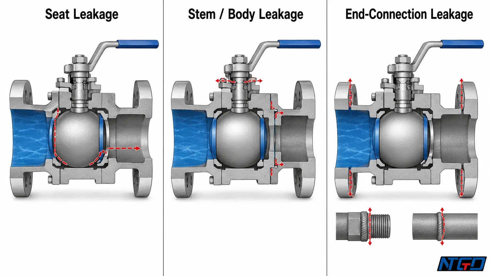
A valve can shut off internally while leaking through a flange gasket. It can also have a sound pipe-end joint while leaking from the stem packing. Treating these as the same failure mechanism leads to poor diagnosis and poor selection.
For component-level context on seats, stem packing, body joints, seals, and pipeline interfaces, review the Руководство по деталям и компонентам шаровых кранов.
Что должно быть подтверждено производителем клапана
The manufacturer should confirm that the requested connection is available and suitable within the complete valve configuration.
Confirmation should include, as applicable:
- Available end form;
- Complete pressure-temperature rating;
- Body, seat, packing, and seal compatibility;
- Connection and face-to-face dimensions;
- Flange facing or thread form;
- Weld-end preparation;
- Weight and support considerations;
- Welding or installation limitations;
- Testing scope;
- Approved drawing and datasheet.

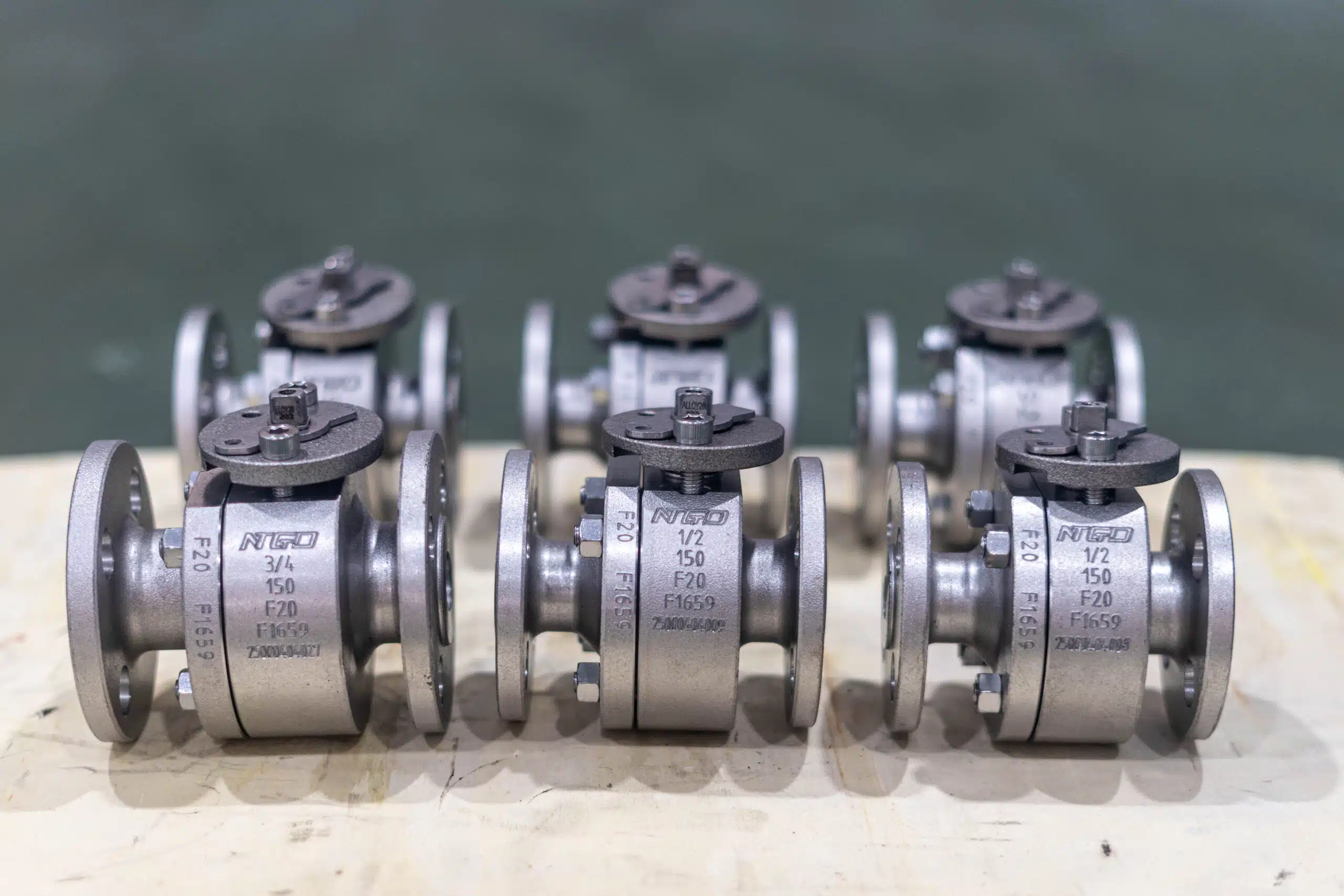
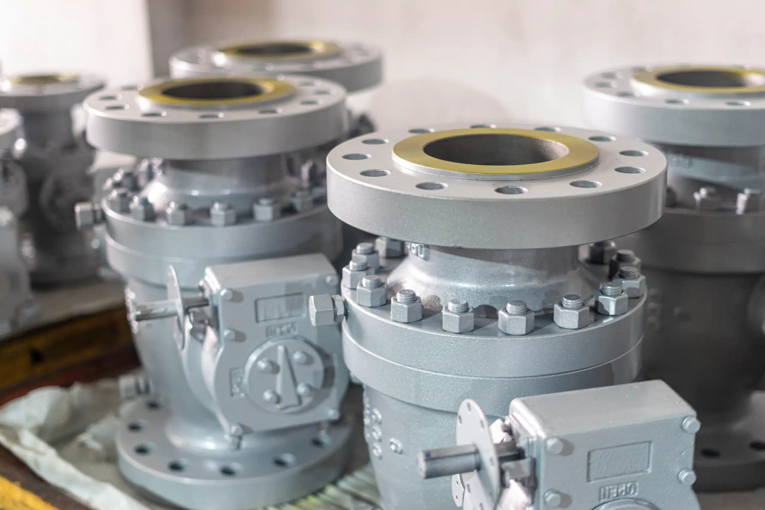
Real gear-operated flanged ball valves illustrate why dimensions, ratings and operating configurations require product-specific confirmation.
Manufacturer confirmation does not replace project engineering. It verifies the proposed valve against the data supplied by the buyer or EPC.
Является ли шаровой кран с пластинчатым уплотнением одним из типов концевых соединений?
A wafer-pattern ball valve is sometimes marketed as an end-connection option, but its engineering classification is more specific.
It is a compact valve body installed between pipeline flanges and retained by through-bolts, studs, or another manufacturer-defined bolting arrangement. The valve therefore depends on the surrounding flange system even though it has no conventional integral end flanges.
For this reason, a wafer-pattern ball valve is a special flange-mounted arrangement, not a fifth pipe-end preparation parallel to flanged, threaded, socket weld, and butt weld ends.
Как устанавливается шаровой кран с пластинчатым узором между фланцами труб
A typical special flange-mounted arrangement includes:
- A pipeline flange on each side;
- The wafer-pattern valve body centered between them;
- Compatible sealing faces or gaskets;
- Through-bolts, studs, or specified fasteners;
- Controlled alignment and tightening;
- Appropriate piping and valve support.
The valve uses the pipeline flanges and through-bolting to form its installed interface. It therefore “borrows” the surrounding flange system rather than providing a separate fifth pipe-end preparation of its own.
A wafer-pattern ball valve must not be described as requiring no flanges or bolts. Its compact body may omit integral valve flanges, but the completed installation still depends on the mating pipeline flanges and bolting.
Чем монтаж на подложке отличается от монтажа с интегрированным фланцевым концом
An integral flanged ball valve has defined valve-end flanges that mate directly with the pipeline flanges. Each end forms a conventional flange joint.
A wafer-pattern ball valve has a slimmer body positioned within the flange-bolting envelope. The pipeline flanges and through-bolting retain the valve assembly.
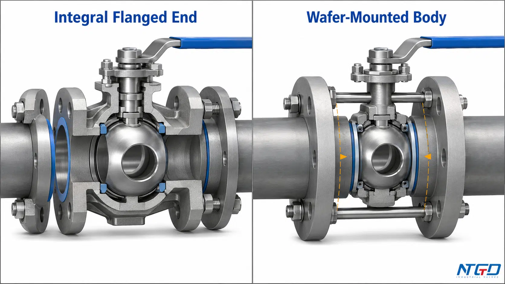
Это различие влияет на:
- Face-to-face length;
- Bolt or stud arrangement;
- Installation alignment;
- Removal clearance;
- Gasket interfaces;
- Pipe support;
- Dead-end capability;
- Product availability and rating.
Wafer mounting may reduce installed length and weight, but compactness is not universal technical superiority. The required size, rating, gasket arrangement, bolting, dead-end capability, and installation limits must be confirmed from the specific product datasheet and instructions.
Product-specific face-to-face dimensions, flange compatibility, bolting, gasket requirements, rating, and installation limits should be confirmed on the wafer ball valve product page.
Что необходимо проверить перед выбором схемы размещения пластин
Подтверждаю:
- Compatible pipeline flange arrangement;
- Gasket or sealing requirement;
- Bolt or stud configuration;
- Face-to-face dimensions;
- Available size and rating;
- Alignment and support;
- Maintenance and flange-separation space;
- External-load limits;
- Dead-end capability;
- Manufacturer installation instructions.
Dead-end service cannot be assumed from the term “wafer-pattern.” Suitability remains design- and manufacturer-specific.
Распространённые ошибки при выборе типов соединений для шаровых кранов
Сочетание типа соединения с другими классификациями шаровых кранов
Calling a valve “three-piece,” “full-port,” “trunnion-mounted,” or “pneumatic” does not state how it connects to the piping.
Possible consequence: The RFQ may appear complete while omitting the pipe interface. The delivered valve may then require an unplanned adapter, transition spool, or replacement before it can be installed.
Required check: Specify the end connection separately from body construction, bore, ball support, material, seat, and actuation.
Предполагаемые имена соединений определяют номинальное давление
Statements such as “flanged means high pressure” or “threaded means low pressure” reduce a multi-layer rating decision to one label.
Possible consequence: The connection may fit the piping while the complete valve remains unsuitable because of the body, seats, packing, material, temperature limit, or completed joint.
Required check: Confirm the complete valve rating and installed joint rather than relying on the connection family. A poor assumption may remain hidden until commissioning, the first shutdown, or valve replacement, when additional field work is most disruptive.
Игнорирование совместимости, выравнивания или зазора для демонтажа
A flange may have the wrong facing or bolting arrangement. A thread may engage partially while being incompatible. A valve may fit the operating space but have no practical removal path.
Possible consequence: Field rework, incomplete thread engagement, gasket leakage, piping stress, extended shutdown, or a spare valve that cannot directly replace the installed unit.
Required check: Review the mating interface, approved dimensions, assembly envelope, rotation space, flange-separation space, and support before ordering.
Рассмотрение сварных или резьбовых соединений как автоматически герметичных или удобных в обслуживании
A welded joint depends on fit-up, welding, inspection, and service loads. A threaded joint depends on compatibility, condition, engagement, sealing method, and assembly control.
Possible consequence: The connection name creates false confidence while installation defects or an impractical replacement plan remain unaddressed.
Required check: Evaluate the completed joint and lifecycle plan. Connection type is not a performance guarantee.
Что следует указать в запросе предложений на поставку шаровых кранов
A useful RFQ separates project inputs from manufacturer confirmation.
Информация, которую должен предоставить Покупатель или EPC
Provide the project information that defines the required interface and service:
- Valve and pipe size;
- Design pressure and temperature;
- Fluid and relevant corrosion, solids, cleanliness, or hazard conditions;
- Required end-connection type and applicable piping interface;
- Pipeline material;
- Required body, seat, bore, and actuation configuration;
- Installation-space and orientation constraints;
- Maintenance and replacement strategy;
- Inspection, testing, drawing, and documentation requirements.
Информация, которую должен подтвердить производитель клапана
The manufacturer should confirm:
- Availability of the requested end form;
- Complete valve rating and material compatibility;
- Connection, face-to-face, or end-to-end dimensions;
- Flange facing, thread form, or weld-end preparation;
- Installation and welding limitations;
- Weight and support considerations;
- Testing scope;
- Approved drawing, datasheet, and stated deviations.
Данные, относящиеся к конкретным типам соединений: фланцевые, резьбовые и сварные концы
| Пункт RFQ | Buyer / EPC Provides | Manufacturer Confirms |
|---|---|---|
| Фланцевый конец | Flange requirement, nominal size, pressure designation, facing and project gasket/bolting basis | Available flange configuration, dimensions, facing, complete rating and drawing |
| Резьбовой конец | Thread family, size, male/female requirement, tapered or parallel form and intended sealing method | Exact machined thread, compatible sealing arrangement, complete rating and drawing |
| Socket Weld end | Required interface, pipe material, dimensional basis and project welding requirements | Socket detail, fit-up limits, heat precautions, rating and drawing |
| Butt Weld end | End-preparation basis, pipe material, wall condition, welding and inspection requirements | End geometry, wall transition, material compatibility, rating and approved preparation drawing |
| Wafer-pattern arrangement | Mating flanges, line dimensions, bolting basis, gasket requirement and installation constraints | Compatible flange system, bolt/stud requirements, face-to-face, rating, dead-end capability and instructions |
Avoid vague RFQ descriptions such as “standard connection” or “normal thread.” These expressions transfer critical compatibility decisions to assumptions.
Часто задаваемые вопросы
Каковы основные типы концевых соединений для промышленных шаровых кранов?
Существует четыре основных типа соединений: фланцевые, резьбовые, сварные с вставкой и стыковые. Фланцевые и резьбовые соединения допускают механический демонтаж, хотя конкретный способ демонтажа зависит от конфигурации. Для полного демонтажа клапана соединения с вставкой и стыковые соединения, как правило, требуют резки и пересварки.
В чём заключается практическое отличие между шаровым краном с фланцевым соединением и шаровым краном с резьбовым соединением?
В клапане с фланцевым соединением используются соприкасающиеся поверхности фланцев, прокладка и болтовое соединение. В клапане с резьбовым соединением используются совместимые наружная и внутренняя резьба с необходимым способом уплотнения. Фланцевые соединения, как правило, обеспечивают более предсказуемую плоскость разъединения, тогда как демонтаж резьбовых соединений зависит от пространства для поворота, соединительных муфт и окружающих трубопроводов.
Чем отличаются концы шаровых кранов с муфтовым и стыковым сварными соединениями?
Концевая часть с муфтовым соединением принимает трубу внутрь углубленной муфты перед внешней сваркой. Концевая часть со стыковым соединением обеспечивает непосредственное совмещение подготовленных концов клапана и трубы. Их прилегание, внутренняя геометрия, доступ для контроля, контроль температуры и требования к ремонту различаются.
Можно ли определить номинальное давление клапана по типу торцевого соединения?
Одно только соединение на выходе не определяет полные рабочие характеристики клапана. Корпус, седла, уплотнение, материалы, размер, температура, соединительные элементы, эксплуатационные нагрузки и технические характеристики, указанные в паспорте производителя, могут устанавливать более низкие предельные значения.
Можно ли демонтировать сварной шаровой кран, не разрезая трубу?
Для полного демонтажа обычно требуется разрезание, а затем сварка и проверка. Некоторые клапаны, состоящие из нескольких частей, могут допускать проведение внутреннего технического обслуживания при том, что их торцевые части остаются приваренными к трубопроводу, однако это не равносильно демонтажу клапана целиком.
Какой тип резьбы следует указать в запросе на предложение — NPT, BSPT или BSPP?
Укажите резьбу, требуемую для соединимой трубы или оборудования, а также в соответствии с проектными нормами. В запросе на предложение следует указать семейство резьбы, номинальный размер, тип резьбы (наружная или внутренняя), форму (коническую или параллельную) и способ уплотнения. Одного лишь указания “резьбовой конец” недостаточно.
Шаровой кран с прокладкой — это то же самое, что и фланцевый шаровой кран?
Нет. Шаровой кран с пластинчатым уплотнением представляет собой специальную конструкцию фланцевого типа, зажатую между фланцами трубопровода; он не имеет традиционных встроенных фланцев на концах клапана. Требования к прокладке, крепежу, номинальной нагрузке, опоре и предельным значениям в тупиковых условиях необходимо уточнять в документации по конкретному изделию.
Заключение
Четыре основные отрасли промышленности Типы концевых соединений шаровых кранов are flanged, threaded, socket weld, and butt weld.
Flanged and threaded ends are mechanically assembled connections, but their removal and sealing logic differ. Socket weld and butt weld ends form welded joints, yet their geometry, fit-up, inspection, cleanability, heat exposure, and repair consequences are not interchangeable.
The connection name alone does not identify the best option or the complete valve rating. Selection must account for:
- The existing piping interface;
- Design pressure and temperature;
- Fluid and material compatibility;
- Installation and maintenance space;
- Vibration and external piping loads;
- Required standards and inspection;
- Future removal and replacement;
- The complete manufacturer-confirmed valve configuration.
A reliable specification identifies the exact connection and also verifies the valve, completed joint, and lifecycle requirements.
Поддержка приложений / спецификаций
To confirm the appropriate end connection for a project, submit the valve and pipe size, design pressure and temperature, fluid, piping material, required connection standard, body and seat requirements, actuation, installation constraints, maintenance strategy, and testing requirements.
These data allow the proposed end connection to be reviewed within the complete valve configuration before the approved drawing, datasheet, and final specification are released.
