
Quick Answer
The four core industrial ball valve end connection types are flanged, threaded, socket weld, and butt weld. Here, ball valve connection types refers specifically to the valve-to-pipe interfaces—not body construction, port design, ball support, or actuation.
Flanged joints use mating flange faces, a gasket, and bolting. Threaded ends use compatible male and female threads with the required sealing method. Socket weld ends accept the pipe inside a recessed socket before external welding, while butt weld ends align the prepared valve and pipe ends directly before welding.
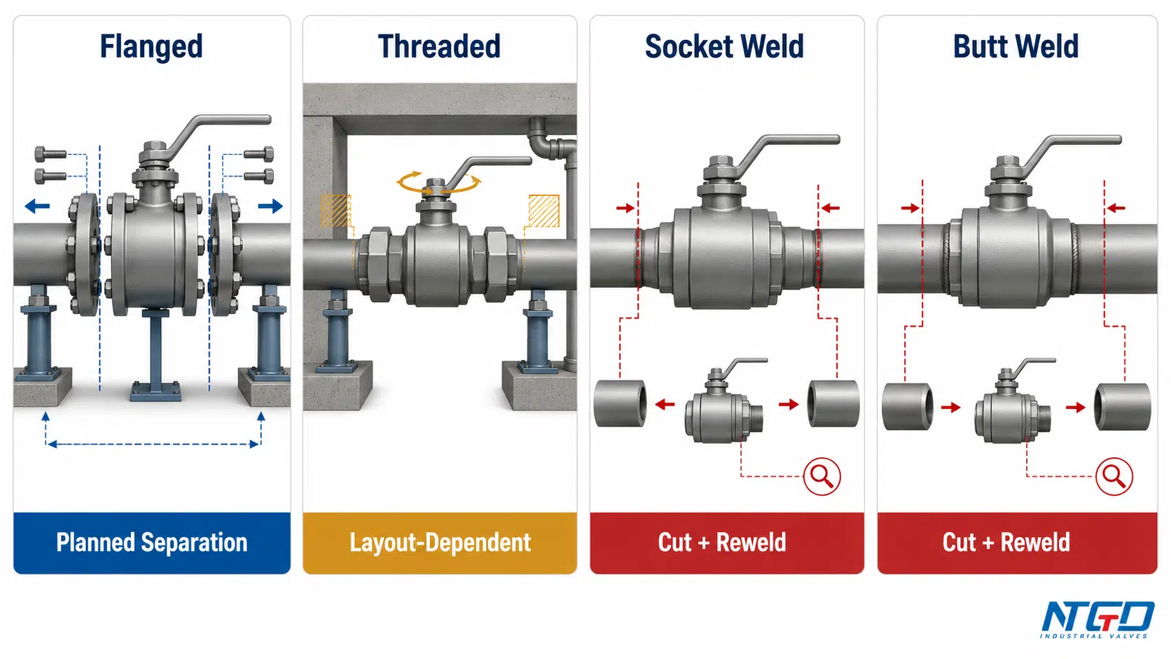
Flanged and threaded connections may support planned removal, although actual serviceability depends on piping support, clearance, corrosion, isolation points, and layout. Socket weld and butt weld connections normally form permanent piping joints and usually require cutting and rework for complete valve removal.
No connection is universally best. Selection must consider the piping interface, pressure and temperature, fluid, maintenance strategy, applicable standards, external loads, and the available valve design. The actual removal path directly affects shutdown planning, spare-valve strategy, and whether the RFQ must specify flange-separation clearance, a union, a removable spool, or a welded replacement plan.
A wafer-pattern ball valve is treated separately because it is a special flange-mounted arrangement rather than a fifth parallel pipe-end preparation.
Choosing an end connection affects more than how the valve is attached to the pipeline. The joint determines where an external leakage path may exist, what installation controls are required, how the valve can be removed, and what information must be stated in the purchase specification.
Two valves may use the same ball, seats, body material, and actuator while having different pipe-end connections. Conversely, two valves with the same end connection may have different body constructions, port designs, pressure-temperature limits, or seat systems. End connection selection is therefore one part of the complete valve specification, not a substitute for it.
This guide defines the classification boundary, compares the four core connections, and maps common project conditions to an initial selection direction. Final suitability must be checked against the project specification, connection requirements, approved manufacturer drawings, and the complete valve datasheet.
What Are Ball Valve End Connection Types?
A ball valve end connection is the interface joining the valve pressure boundary to the adjacent piping. It determines how the valve and pipe mate, where the installed joint seals, what retains the connection, and how the valve can later be removed or replaced.
In this guide, ball valve connection types means the pipe-end connections between an industrial ball valve and the piping system. It does not mean every classification used to describe a ball valve.
End Connection vs. Body, Port, Ball Support and Actuation
Several classification axes are frequently mixed together in product descriptions. Keeping them separate prevents an end-connection selection guide from becoming an inaccurate list of unrelated ball valve types.
| Classification Axis | What It Describes | Examples |
|---|---|---|
| End connection | How the valve joins the piping | Flanged, threaded, socket weld, butt weld |
| Body construction | How the pressure-containing body is assembled | One-piece, two-piece, three-piece |
| Ball support | How the ball is supported internally | Floating, trunnion-mounted |
| Port design | Shape and area of the flow passage | Full bore, reduced bore, V-port |
| Actuation | How operating torque is applied | Manual, pneumatic, electric |
A three-piece ball valve may be supplied with threaded, socket weld, or butt weld ends. A trunnion-mounted ball valve may be flanged or welded. None of these body or internal classifications identifies the pipe-end connection.
The distinction also matters for maintenance. A three-piece body may provide access to internal components under suitable conditions, but welded pipe ends can still prevent removal of the complete valve without cutting the piping. Body serviceability and pipeline removability are related, but they are not the same feature.
An RFQ that states only “three-piece,” “full-port,” or “trunnion-mounted” remains incomplete. Without a separate end-connection specification, the delivered valve may not mate with the site piping even when every other product description is correct.
Readers who need the broader design taxonomy can review the main ball valve types and selection guide, which separates floating, trunnion-mounted, port, body-entry, and other design categories from pipe-end connections.
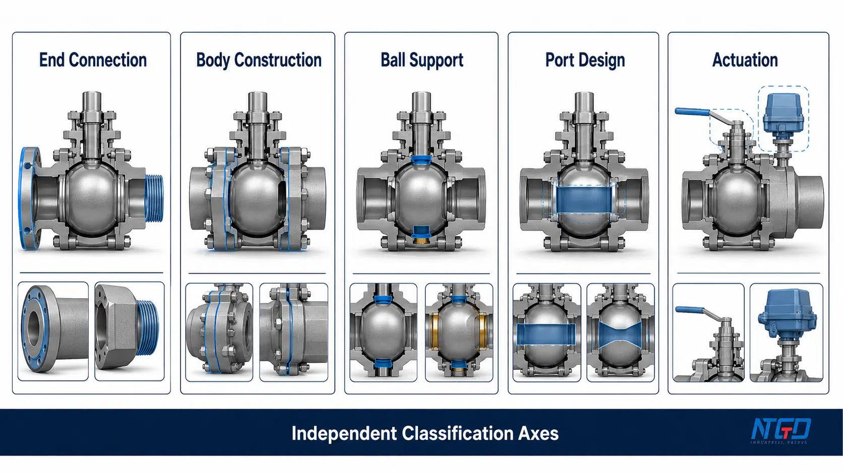
Core Pipe-End Connections vs. Special Mounting Arrangements
For industrial ball valve selection, the four primary pipe-end groups are:
- Flanged end connections;
- Threaded end connections;
- Socket weld end connections;
- Butt weld end connections.
Specialized systems may use other arrangements, but they should not automatically be treated as equal members of this core classification. A wafer-pattern ball valve, for example, is installed between pipeline flanges and relies on a flange-mounted bolting system. It is addressed later as a special mounting arrangement.
The same scope boundary applies to sanitary, grooved, union, and other application-specific interfaces. Their existence does not require an industrial ball valve end-connection guide to become an encyclopedia of every possible piping connection.
The Four Core Ball Valve End Connections
The following table compares the four connection groups at the installed-joint level. It does not assign universal size, pressure, or temperature limits. Those limits depend on the complete valve design, materials, seat system, connection requirement, and manufacturer documentation.
| Connection Type | Joint Mechanism | Primary External Sealing Interface | Removal Direction | Main Installation Control | Maintenance Consequence | Typical Initial Direction | Main Caution |
|---|---|---|---|---|---|---|---|
| Flanged | Mating valve and pipe flanges secured by bolting | Gasket or specified flange-face sealing system | Planned disassembly is possible | Compatibility, alignment, gasket condition and controlled bolting | Removal is possible after isolation, support and adequate flange separation | Standardized process piping and planned maintenance access | Misalignment or uneven loading can reduce gasket load and add piping stress |
| Threaded | Compatible male and female threads are engaged | Mating thread engagement and/or a specified sealing element | Potentially removable, but layout-dependent | Thread form, engagement, torque, cleanliness and sealing method | Removal may require rotation, a union, spool removal or pipe movement | Compact piping and matching threaded equipment interfaces | Mismatch, galling, overtightening or insufficient clearance can prevent sealing or later removal |
| Socket Weld | Pipe enters a recessed valve socket and is externally welded | Completed socket-weld joint | Normally requires cutting or welded rework | Fit-up, insertion condition, heat control and weld quality | Complete removal generally transfers work to cutting, rewelding and reinspection | Project-specified compact welded piping | Heat and socket geometry may require seat, cleanability and corrosion review |
| Butt Weld | Prepared valve and pipe ends are aligned end-to-end and welded | Completed butt-weld joint | Normally requires cutting and rewelding | End preparation, axial alignment, welding and inspection requirements | Replacement requires a planned cutting, repair and inspection strategy | Project-specified continuous welded piping | Integrity depends on preparation, alignment, welding, inspection and service loads |
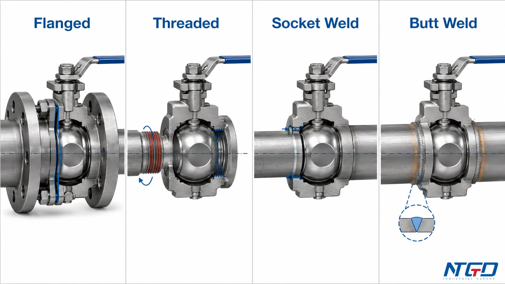
The valve body may be similar, but the connection can create a very different shutdown and spare strategy. A mechanically removable joint may require more installation space and hardware, while a welded joint may reduce detachable interfaces but make complete replacement dependent on field cutting, welding, and reinspection.
Flanged End Connections
A flanged ball valve has integral or otherwise specified flange ends that mate with corresponding pipeline flanges. Bolting retains the installed joint, while the external seal is formed at the mating faces by the specified gasket or sealing arrangement.
The joint must be treated as a complete system rather than two metal discs placed together. Compatibility includes the flange requirement, nominal size, pressure designation, facing, gasket, bolt pattern, bolting material, and installation envelope.
For available flange configurations, materials, and product-level specification checks, review the flanged ball valve product page.
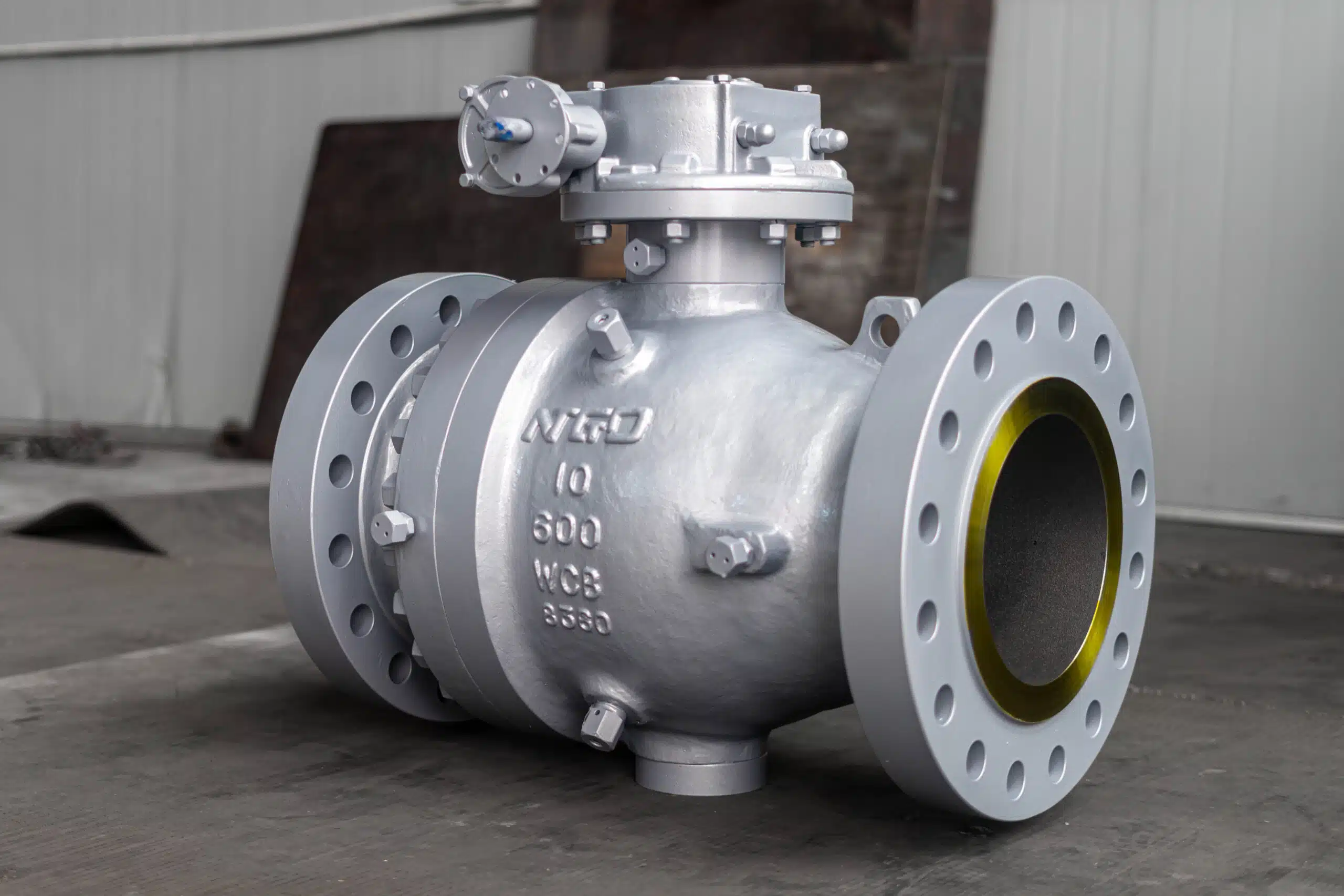
Flanged ends are commonly considered where the piping system already uses standardized flange interfaces or where planned valve removal is important. They allow the valve to be separated from the line without cutting its pressure-boundary ends, but removal still requires:
- Safe isolation and depressurization;
- Support for the valve and adjacent piping;
- Access to remove the bolting;
- Enough flange separation to extract the valve;
- Inspection or replacement of the gasket;
- Controlled alignment and reassembly.
Detailed alignment, gasket, bolt-tightening, installation, disassembly, and maintenance considerations are covered in the flange ball valve installation and maintenance guide.
Poor pipe alignment must not be corrected by pulling the flanges together with the bolts. That practice can distort gasket loading, transfer external loads into the valve body, and create an avoidable leakage path.
Alignment and independent support become especially important when valve or actuator weight, thermal movement, larger flange loads, or substantial external piping loads increase the forces acting on the joint. The piping should support the installed system rather than use the valve as an alignment device.
Threaded End Connections
Threaded ball valves connect directly to compatible threaded pipe ends or equipment ports. A valve may have female, male, or mixed threaded ends, depending on the design.
“Threaded” alone is not a complete connection specification. The buyer must identify the thread family, nominal size, male or female configuration, tapered or parallel form, and intended sealing method. Threads that appear to engage may still be incompatible in pitch, profile, taper, or sealing principle.
NPT, BSPT, and BSPP are therefore not interchangeable labels. Tapered threads and parallel threads use different engagement and sealing arrangements. The RFQ must match the valve thread to the mating piping component and the project requirement rather than relying on a generic “threaded end” description.
For NPT connections, the ASME B1.20.1 pipe-thread standard provides the reference for thread dimensions and gaging; BSPT and BSPP must be specified under their own applicable requirements rather than treated as NPT equivalents.
Threaded ends are often considered for compact installations and matching threaded equipment ports. Their smaller installed envelope can be useful where flange clearance is unavailable. Installation quality still depends on:
- Correct thread compatibility;
- Clean and undamaged threads;
- Adequate engagement;
- Controlled assembly torque;
- A sealing method compatible with the connection and fluid;
- Avoiding excessive torsional load on the valve body.
Threaded does not automatically mean easy to remove. A valve trapped between rigid threaded pipes may require pipe disturbance or cutting if it cannot rotate and no removable joint has been planned.
Engineers should establish the isolation points, rotation clearance, and removal path during piping-layout development. The result often determines whether the RFQ must include a union, removable spool, or another deliberate separation point.
Socket Weld End Connections
A socket weld ball valve has a recessed socket in each valve end. The pipe enters the socket and an external weld completes the joint.
The socket assists initial positioning, but joint quality still depends on fit-up, heat control, material compatibility, welding quality, and any project-required inspection. The connection removes a threaded pipe joint, but it does not create an automatically leak-free or maintenance-free installation.
Welding heat can travel toward the body, seats, seals, and body joints. When soft seats are close to the weld zone, the manufacturer’s installation limits and heat-control requirements must be established before site work begins.
The socket recess also creates an internal geometry that may matter in services sensitive to crevice corrosion, retained product, solids, or process cleanliness. Where these risks or future replacement difficulties are significant, socket weld suitability should be confirmed against the specific valve design and maintenance plan.
For product-specific socket dimensions, ratings, body configurations, installation limits, and replacement checks, use the dedicated socket weld ball valve selection guide.
Butt Weld End Connections
Butt weld ball valves have prepared ends that align directly with prepared pipe ends. The valve and pipe ends are then joined through the project-defined butt-weld arrangement.
Unlike socket weld, the pipe does not terminate inside a recessed valve socket. The valve and pipe ends must be compatible in diameter, wall condition, end preparation, material, and alignment. Joint quality depends on the approved welding and inspection requirements for the project.
Butt weld ends are commonly considered where the piping design requires a continuous welded arrangement. They may reduce detachable mechanical joints, but external loading, thermal effects, inspection access, repair strategy, and material compatibility remain part of the installed design.
A butt weld connection should not be selected solely because the service is described as high pressure or critical. The end form must follow the piping design basis and complete valve specification. The manufacturer must confirm the valve-end preparation, wall transition, material, rating, and construction against the project requirements.
Complete valve removal usually requires cutting the line and performing new welding and inspection. Shutdown time, support, replacement length, access, and field-repair capability must be planned before the connection is specified.
Flanged vs Threaded Ball Valves: How to Choose the Right End Connection
The essential difference is the installed joint.
A flanged ball valve uses matching flange faces, bolting, and a gasket or specified flange seal. A threaded ball valve uses compatible male and female threads with the sealing method required by that thread design.
Flanged connections generally provide a clearer planned-disassembly path. Threaded connections generally provide a smaller installed envelope. Neither statement is absolute. A flanged valve may remain difficult to remove without support and separation space, while a threaded valve may be impossible to rotate out of a rigid piping run.
| Comparison Factor | Flanged Ball Valve | Threaded Ball Valve |
|---|---|---|
| Joint mechanism | Bolted mating flanges | Engaged male and female threads |
| External sealing interface | Gasket or specified flange-face sealing arrangement | Thread engagement and/or specified independent sealing element |
| Required connection data | Flange requirement, size, pressure designation, facing, gasket and bolting basis | Thread family, size, tapered or parallel form, male/female arrangement and sealing method |
| Installed envelope | Larger because of flange faces and bolting | Usually more compact after installation |
| Installation control | Alignment and gasket loading must be controlled; forcing misaligned flanges together can create joint leakage and body load | Compatibility and assembly torque must be controlled; mismatch or overtightening can damage the joint before service begins |
| Removal reality | Provides a defined separation plane, but only when isolation, support, bolt access and flange separation are available | Mechanical removal depends on rotation space and a planned union or spool; otherwise field pipe work may still be required |
| Maintenance access | Often easier to plan into process piping | Convenient only when the piping arrangement supports disassembly |
| External-load concern | Flange misalignment, bolt loading and pipe bending | Torsional assembly load, thread stress and pipe restraint |
| Vibration review | Requires review of support, bolting, gasket behavior and cyclic loading | Requires review of engagement, support, sealing system and cyclic loading |
| Damage concern | Flange-face damage, gasket damage or uneven loading | Cross-threading, overtightening, galling or damaged threads |
| Upfront cost direction | Usually requires more connection hardware, space and assembly work | Often uses fewer separate joint components |
| Lifecycle implication | Planned gasket and bolting renewal can make future disassembly more predictable when clearance is provided | Reuse and replacement become less predictable if threads seize, gall or cannot be rotated out of the piping |
| Typical initial direction | Standardized process piping and planned periodic removal | Compact piping with a confirmed threaded interface |
| Must verify | Approved flange configuration, complete valve datasheet, alignment and removal clearance | Exact thread specification, complete valve datasheet, sealing method and removal path |
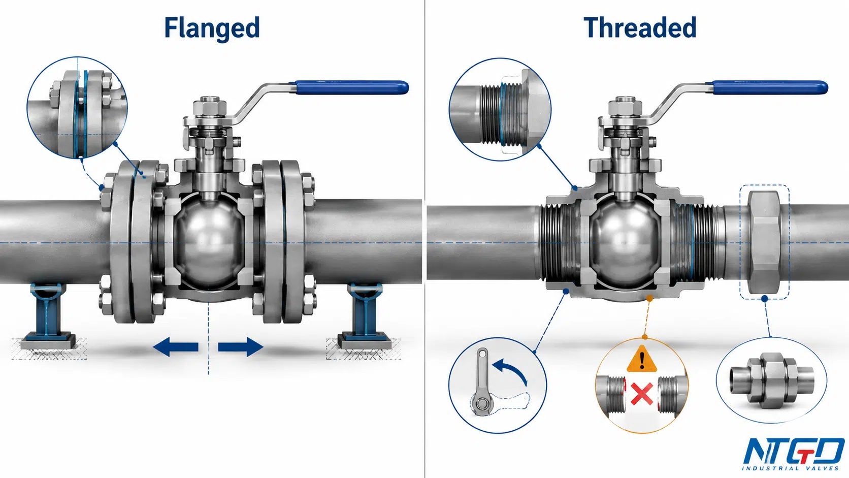
Bolted-and-Gasketed Joint vs. Mating Pipe Threads
Flanged and threaded connections place the external sealing function in different locations.
In a flange joint, bolting creates the load needed to compress the gasket or specified seal between the mating faces. Installed integrity depends on the condition and compatibility of the flange faces, gasket, bolting, alignment, and applied load.
In a threaded joint, the sealing mechanism depends on the thread design. Some connections use tapered engagement with a compatible sealing compound or tape; parallel-thread arrangements commonly depend on a separate sealing feature. A connection may engage mechanically and still fail to provide the intended seal.
Installation Space, Alignment and Thread Compatibility
A threaded valve normally occupies less space after installation, but the installer may need enough room to rotate the valve or adjacent pipe. A compact final envelope does not guarantee a compact assembly or removal procedure.
A flanged valve requires room for flange hardware, bolt access, support, and later flange separation. The piping must align without using the flange bolts to force the valve into the gap.
The decision should account for both:
- Operating envelope: the space occupied after installation;
- Installation and maintenance envelope: the space needed to assemble, rotate, separate, remove, and reinstall the valve.
Removal and Maintenance Are Not Equally Simple
Flanged valves are often selected where planned removal is expected because routine removal does not require cutting the valve ends. The piping must still be isolated, depressurized, supported, and separated safely.
Threaded valves can be removed without cutting only when the layout permits rotation or includes a union, disconnect, or removable spool. A valve trapped between two rigid threaded pipe ends may be less maintainable than its compact shape suggests.
Material and condition also affect removal. Stainless-steel threaded joints may require controlled assembly practices to manage galling. Corrosion, damaged threads, excessive sealing material, or previous overtightening can prevent reliable reuse.
When Each Connection Is Commonly Considered
A flanged connection may be an initial direction when:
- The piping system already uses matching flanges;
- Periodic complete removal is expected;
- A standardized gasketed and bolted interface is required;
- Valve or actuator weight calls for a planned supported installation;
- Future replacement should avoid cutting the pipe ends.
A threaded connection may be an initial direction when:
- The mating pipe or equipment has the specified thread;
- Installed space is limited;
- The layout permits controlled assembly and future removal;
- The valve is available with the exact required thread;
- The project permits a threaded joint for the service.
Neither connection should be selected through a universal pressure or pipe-size rule. The verified complete-valve rating and the completed installed joint always override generalizations attached to a connection family.
Socket Weld vs Butt Weld Ball Valves: Key Engineering Differences
Socket weld and butt weld ball valves both form welded pipe joints, but the joint geometry and field controls differ.
A socket weld joint inserts the pipe into a recessed valve-end socket before external welding. A butt weld joint aligns prepared valve and pipe ends directly before welding.
| Engineering Point | Socket Weld | Butt Weld |
|---|---|---|
| Joint geometry | Pipe inserted into a recessed socket | Prepared ends aligned end-to-end |
| Weld arrangement | External socket weld | Butt or groove weld defined by the project |
| Fit-up focus | Pipe insertion, socket condition, specified allowance and orientation | End preparation, wall compatibility and axial alignment |
| Internal geometry | Socket transition may create an internal discontinuity | Can provide a more continuous transition when correctly matched and aligned |
| Heat concern | Heat transfer toward the valve body and soft parts | Heat transfer across the end-to-end weld zone |
| Cleanability concern | Socket recess may require review for crevice or retention risks | Internal mismatch or weld condition requires review |
| Inspection | Defined by the project, material and joint requirements | Defined by the project, material and joint requirements |
| Removal | Usually requires cutting and welded rework | Usually requires cutting and welded rework |
| Typical initial direction | Project-specified compact welded piping | Project-specified continuous welded piping |
| Main caution | Socket geometry does not remove heat, cleanliness or maintenance constraints | A butt weld end does not make the complete valve automatically suitable for critical service |
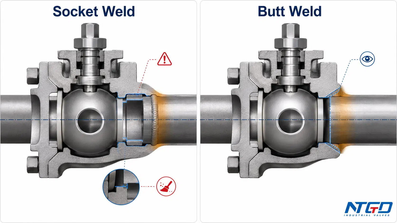
Socket Insertion and External Weld vs. End-to-End Weld Preparation
The socket provides a physical recess for pipe insertion, but dimensional and procedural control remain necessary. The valve end, pipe outside diameter, insertion condition, orientation, and approved installation method must be compatible.
Butt weld ends require direct matching of valve and pipe preparations. Mismatch in end geometry, wall transition, or alignment can complicate welding, inspection, and internal flow continuity.
These checks belong before delivery to site. Discovering an incompatible end preparation after the piping has been positioned can require a transition piece, replacement valve, or field modification.
Heat, Fit-Up, Inspection and Cleanability Considerations
Welding heat can affect seats, seals, body joints, coatings, and adjacent components. The actual risk depends on the valve design, material, wall section, welding process, sequence, cooling method, and manufacturer instructions.
For a soft-seated valve, the connection choice must be reviewed together with the distance between the weld zone and temperature-sensitive components. A workable welded-end design is one for which the manufacturer has defined installation limits and the site can realistically follow them.
Socket weld geometry also deserves added review when the service is sensitive to crevice corrosion, retained material, solids, or process cleanliness. Butt weld geometry requires close control of alignment, wall transition, root condition, and inspection access.
TWI’s socket-weld technical overview illustrates the recessed-socket geometry and explains why the internal recess and required gap can create retention and cleanability concerns.
This guide does not define a welding procedure. Qualification, inspection method, acceptance criteria, and post-weld requirements belong to the project engineering and quality system.
Removal, Repair and Lifecycle Consequences
Both welded end forms shift maintenance effort from mechanical disassembly to cutting, preparation, rewelding, and reinspection.
A three-piece ball valve may allow internal servicing while the end pieces remain in the line, but this does not make the complete welded valve removable. The maintenance plan should distinguish:
- Servicing internal parts with the ends left in the piping;
- Removing the complete pressure-containing assembly;
- Repairing a damaged welded end;
- Re-establishing and reinspecting the piping joint.
Where rapid replacement matters, welded-end serviceability should be evaluated before the end connection is selected.
How to Select the Right Ball Valve End Connection
A useful selection process does not begin with “Which connection is strongest?” It begins with the piping system, operating conditions, maintenance plan, and specified interface.
Available Valve Size and Matching Piping Interface
First confirm that the required valve design is available with an end connection matching the piping system.
Check:
- Nominal valve and pipe size;
- Pipe schedule or end geometry where relevant;
- Existing flange, thread, socket, or weld-end requirement;
- Available valve body construction;
- Face-to-face or end-to-end space;
- Required transition between valve and piping.
A theoretically preferred connection has little value if it is unavailable with the required body construction, material, bore, seat design, or actuator arrangement.
Ignoring the actual interface can turn a simple valve installation into a field transition-spool, adapter, or replacement-valve problem. Product availability, piping requirements, maintenance, and project standards must take priority over universal size rules.
Design Pressure, Temperature and Fluid Compatibility
The end connection contributes to installed-joint suitability but does not define the complete valve pressure-temperature capability.
Check:
- Design and operating pressure;
- Design and operating temperature;
- Pressure and temperature cycles;
- Fluid composition and phase;
- Corrosion, erosion, solids, or contamination;
- Hazard and leakage consequence;
- Body material;
- Seat, seal, and packing materials;
- Joint components and sealing materials.
For flanged joints, gasket and bolting suitability matter. For threaded joints, the exact thread and sealing arrangement matter. For welded joints, pipe and valve-end material compatibility, heat effects, and project welding requirements matter.
A joint may satisfy its connection requirement while the complete valve remains unsuitable because of its seat, packing, body material, construction, or temperature limit. Connection verification and complete-valve verification must therefore be completed together.
Installation Space and Maintenance Access
Selection must account for both installation and future maintenance.
For flanged ends, review:
- Bolt access;
- Valve lifting and support;
- Flange-separation space;
- Gasket replacement access;
- Adjacent equipment and insulation;
- Actuator clearance.
For threaded ends, review:
- Rotation clearance;
- Wrench access;
- Whether the valve or pipe can rotate;
- Availability of a union or removable spool;
- Risk of thread seizure or damage.
For welded ends, review:
- Welding and inspection access;
- Heat-control requirements;
- Cutting and replacement space;
- Shutdown and field-repair capability.
A valve that fits the operating space may still be impossible to remove within the available shutdown window. Maintenance access must be treated as a design input, not an assumption left for the site team.
Broader checks for Cv, port size, pressure drop, installation space, connection fit, and final testing are covered in the ball valve sizing and installation guide.
Vibration, Piping Loads and Alignment
No connection family determines vibration performance by name alone.
Review:
- Pipe support locations;
- Valve and actuator weight;
- Thermal movement;
- Cyclic bending;
- Installation misalignment;
- Pump- or compressor-induced vibration;
- Water hammer or other transient loads;
- External nozzle loads;
- Maintenance-induced pipe movement.
A flange joint may lose uniform gasket loading or experience bolt relaxation. A threaded joint may be exposed to torsional stress, loosening, or fatigue near the engaged section. A welded joint may transfer external loading directly into the valve end and body.
Ignoring these loads can produce recurring end-joint leakage, fatigue damage, loosened hardware, or an installation that cannot maintain alignment. The connection must be reviewed as part of the supported piping system.
Applicable Standards, Inspection and Replacement Strategy
Connection compatibility should be stated explicitly in the specification.
Depending on the end form, the RFQ may need to identify:
- Flange requirement and facing;
- Pressure designation;
- Thread family and male/female arrangement;
- Tapered or parallel thread;
- Socket weld interface;
- Butt weld end preparation;
- Material and wall compatibility;
- Required inspection;
- Manufacturer drawing approval.
An incomplete standard or inspection requirement may not be discovered until the valve reaches the site or enters project document review. The result can be rejected drawings, incompatible mating ends, added transition work, or delayed acceptance.
Replacement strategy also matters. A connection efficient during initial construction may be expensive to remove during an unplanned shutdown, while a connection selected for maintainability may require more space and hardware from the outset.
From Project Conditions to a Verified Connection Choice
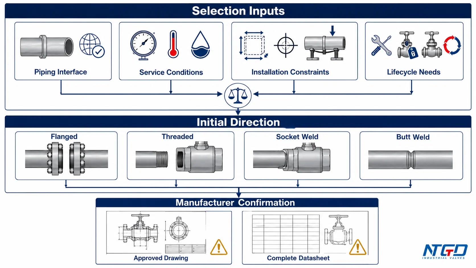
The matrix provides an initial direction, not a universal rule. The project specification, approved manufacturer drawing, and complete valve datasheet take priority over every general selection statement below.
| Project Condition | Initial Direction | Engineering Reason | Must Verify |
|---|---|---|---|
| Existing standardized flanged process piping | Flanged | Matches the established bolted and gasketed interface | Approved flange configuration and datasheet |
| Periodic complete valve removal is expected | Flanged | Provides a defined mechanical separation point | Support and flange-separation clearance |
| Compact line with a matching threaded equipment port | Threaded | Matches the equipment interface without separate flange hardware | Exact thread and removal path |
| Small-bore line with a project-approved threaded joint | Threaded may be considered | Uses an established compact project connection | Service suitability and support |
| Project requires socket weld piping ends | Socket Weld | Matches the specified recessed welded interface | End detail and heat limits |
| Project requires a continuous end-to-end welded joint | Butt Weld | Matches the specified welded piping arrangement | Approved end preparation and inspection |
| Limited installed envelope | Threaded or wafer-pattern arrangement may be reviewed | A smaller installed envelope may help | Assembly space and product datasheet |
| High vibration or cyclic external loading | No automatic choice | Performance depends on support, fit-up and system dynamics | Piping-load review and manufacturer limits |
| Stainless-steel threaded joint | Threaded only after assembly review | Galling may affect installation and reuse | Material pairing and assembly method |
| Hazardous fluid or high leakage consequence | Project-specified connection after detailed review | The complete installed joint carries greater consequence | Code basis and completed-joint verification |
| Rapid future replacement is a priority | Flanged or deliberately removable threaded layout | A planned separation point can reduce field rework | Removal clearance and spare strategy |
| Long piping run with limited shutdown access | Compare welded and removable options by lifecycle requirement | Initial integrity and future repair effort must be balanced | Repair access and replacement plan |
Why the End Connection Does Not Define the Complete Valve Rating
A complete rating check has at least four layers.
1. Complete Valve Pressure Boundary
This includes the body, body joints, stem retention, seats, packing, seals, and other pressure-containing features. The end connection does not determine these features by itself.
2. End-Connection Requirement
The flange, thread, socket, or butt weld end must match the specified piping interface. Compatibility includes geometry, material, rating basis, and dimensional requirements.
3. Installed Joint
The completed joint includes components and workmanship outside the valve:
- Flange gasket and bolting;
- Thread engagement and sealing material;
- Socket weld fit-up and completed weld;
- Butt weld preparation, alignment, completed weld, and inspection.
4. Project Service Conditions
Design pressure and temperature are only part of the service. Cyclic loads, vibration, corrosion, fluid hazard, external piping loads, shutdown frequency, and maintenance access can change connection suitability.
A flanged valve, for example, remains limited by its seats, packing, body material, construction, and other pressure-boundary components. Flanged ends cannot make a valve suitable for a design temperature that exceeds the capability of those components.
The same principle applies to every connection family: the connection label never overrides a limitation in the complete valve or the completed installed joint.
The ASME B16.34 valve standard covers pressure-temperature ratings, materials, dimensions, testing, and marking for flanged, threaded, welding-end, and wafer or flangeless valves, reinforcing why the connection label cannot replace complete-valve verification.
Seat Leakage, Pressure-Boundary Leakage and End-Connection Leakage
The word “leakage” should identify the actual boundary.
| Leakage Boundary | Typical Location | Relationship to End Connection |
|---|---|---|
| Internal seat leakage | Across the closed ball and seats | Primarily affected by seat design, ball condition, differential pressure and service |
| Stem or body pressure-boundary leakage | Stem packing, body joint, closure or pressure-containing component | Primarily affected by valve construction, seals, assembly and operating conditions |
| Pipe-end connection leakage | Flange gasket, threaded joint or welded joint | Directly affected by end compatibility, installation quality and external loads |
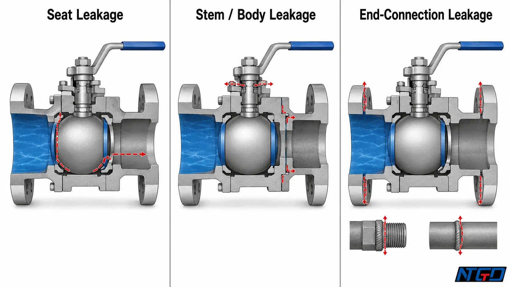
A valve can shut off internally while leaking through a flange gasket. It can also have a sound pipe-end joint while leaking from the stem packing. Treating these as the same failure mechanism leads to poor diagnosis and poor selection.
For component-level context on seats, stem packing, body joints, seals, and pipeline interfaces, review the ball valve parts and components guide.
What Must Be Confirmed by the Valve Manufacturer
The manufacturer should confirm that the requested connection is available and suitable within the complete valve configuration.
Confirmation should include, as applicable:
- Available end form;
- Complete pressure-temperature rating;
- Body, seat, packing, and seal compatibility;
- Connection and face-to-face dimensions;
- Flange facing or thread form;
- Weld-end preparation;
- Weight and support considerations;
- Welding or installation limitations;
- Testing scope;
- Approved drawing and datasheet.

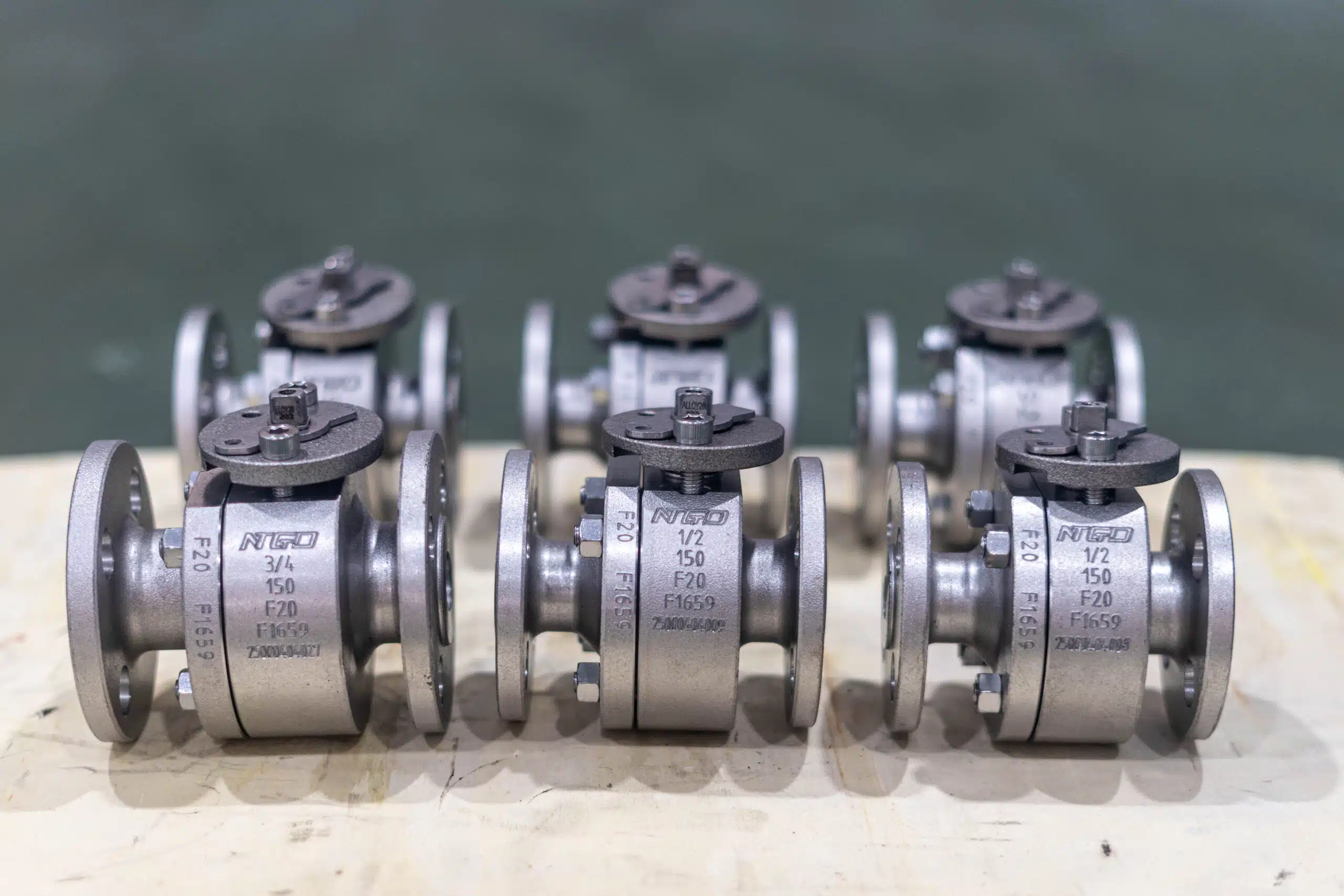
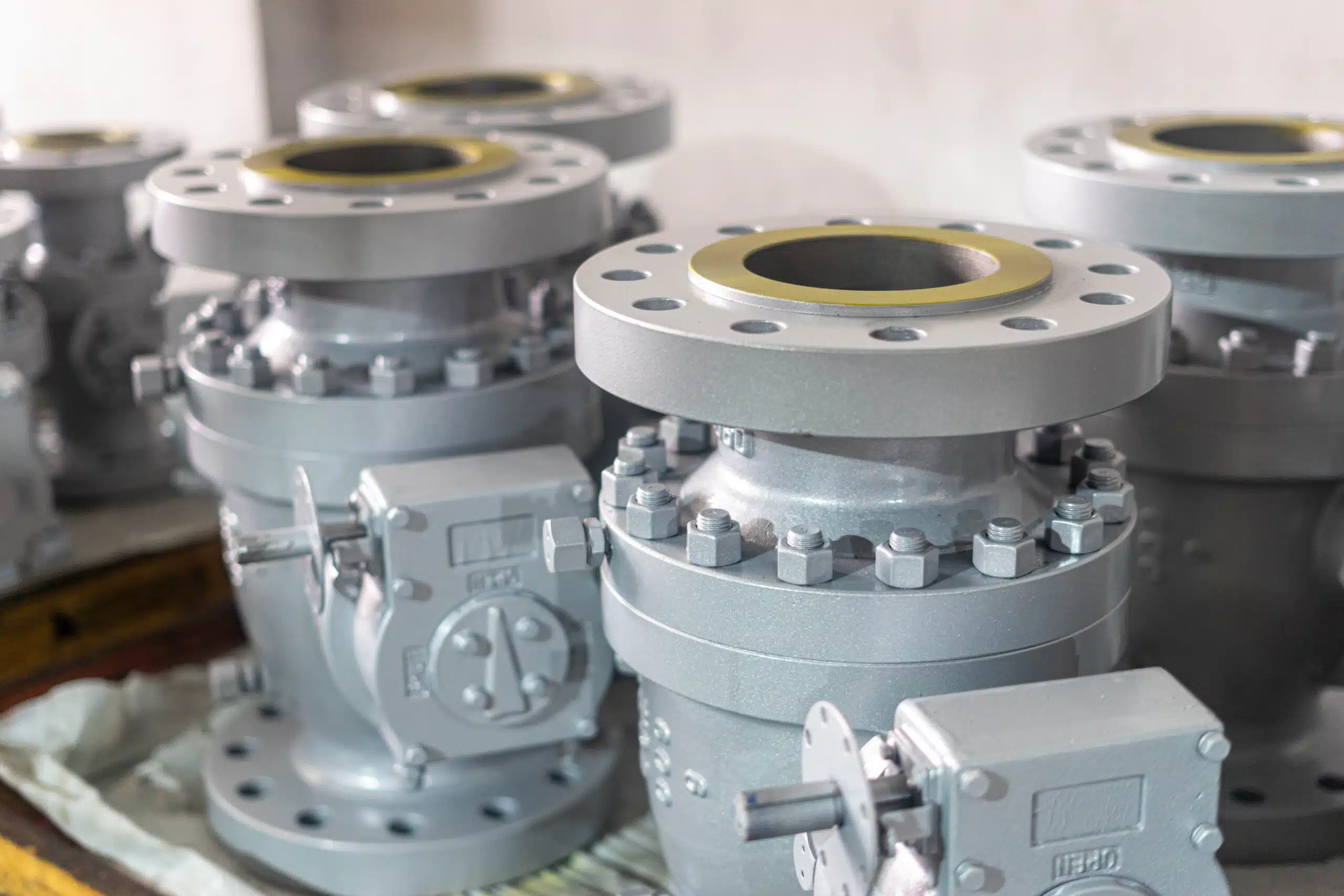
Real gear-operated flanged ball valves illustrate why dimensions, ratings and operating configurations require product-specific confirmation.
Manufacturer confirmation does not replace project engineering. It verifies the proposed valve against the data supplied by the buyer or EPC.
Is a Wafer Ball Valve an End Connection Type?
A wafer-pattern ball valve is sometimes marketed as an end-connection option, but its engineering classification is more specific.
It is a compact valve body installed between pipeline flanges and retained by through-bolts, studs, or another manufacturer-defined bolting arrangement. The valve therefore depends on the surrounding flange system even though it has no conventional integral end flanges.
For this reason, a wafer-pattern ball valve is a special flange-mounted arrangement, not a fifth pipe-end preparation parallel to flanged, threaded, socket weld, and butt weld ends.
How a Wafer-Pattern Ball Valve Is Mounted Between Pipe Flanges
A typical special flange-mounted arrangement includes:
- A pipeline flange on each side;
- The wafer-pattern valve body centered between them;
- Compatible sealing faces or gaskets;
- Through-bolts, studs, or specified fasteners;
- Controlled alignment and tightening;
- Appropriate piping and valve support.
The valve uses the pipeline flanges and through-bolting to form its installed interface. It therefore “borrows” the surrounding flange system rather than providing a separate fifth pipe-end preparation of its own.
A wafer-pattern ball valve must not be described as requiring no flanges or bolts. Its compact body may omit integral valve flanges, but the completed installation still depends on the mating pipeline flanges and bolting.
How Wafer Mounting Differs from an Integral Flanged End
An integral flanged ball valve has defined valve-end flanges that mate directly with the pipeline flanges. Each end forms a conventional flange joint.
A wafer-pattern ball valve has a slimmer body positioned within the flange-bolting envelope. The pipeline flanges and through-bolting retain the valve assembly.
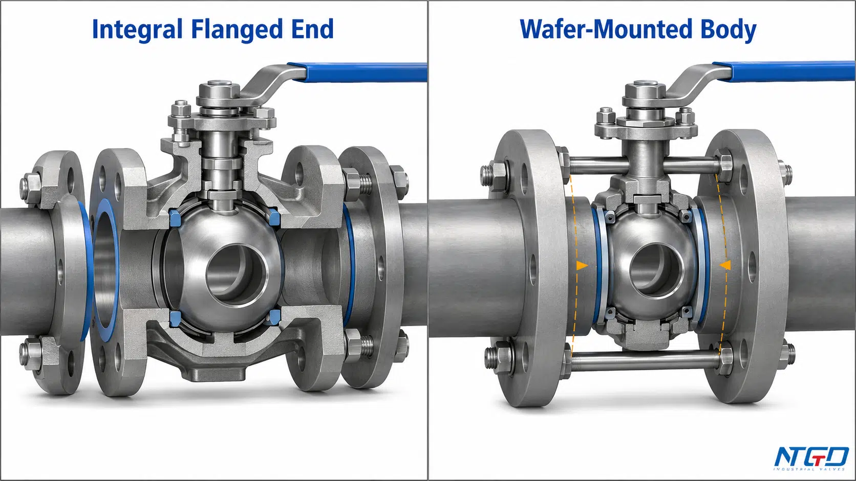
This difference affects:
- Face-to-face length;
- Bolt or stud arrangement;
- Installation alignment;
- Removal clearance;
- Gasket interfaces;
- Pipe support;
- Dead-end capability;
- Product availability and rating.
Wafer mounting may reduce installed length and weight, but compactness is not universal technical superiority. The required size, rating, gasket arrangement, bolting, dead-end capability, and installation limits must be confirmed from the specific product datasheet and instructions.
Product-specific face-to-face dimensions, flange compatibility, bolting, gasket requirements, rating, and installation limits should be confirmed on the wafer ball valve product page.
What Must Be Verified Before Selecting a Wafer Arrangement
Confirm:
- Compatible pipeline flange arrangement;
- Gasket or sealing requirement;
- Bolt or stud configuration;
- Face-to-face dimensions;
- Available size and rating;
- Alignment and support;
- Maintenance and flange-separation space;
- External-load limits;
- Dead-end capability;
- Manufacturer installation instructions.
Dead-end service cannot be assumed from the term “wafer-pattern.” Suitability remains design- and manufacturer-specific.
Common Ball Valve End Connection Selection Mistakes
Mixing Connection Type with Other Ball Valve Classifications
Calling a valve “three-piece,” “full-port,” “trunnion-mounted,” or “pneumatic” does not state how it connects to the piping.
Possible consequence: The RFQ may appear complete while omitting the pipe interface. The delivered valve may then require an unplanned adapter, transition spool, or replacement before it can be installed.
Required check: Specify the end connection separately from body construction, bore, ball support, material, seat, and actuation.
Assuming Connection Names Define Pressure Capability
Statements such as “flanged means high pressure” or “threaded means low pressure” reduce a multi-layer rating decision to one label.
Possible consequence: The connection may fit the piping while the complete valve remains unsuitable because of the body, seats, packing, material, temperature limit, or completed joint.
Required check: Confirm the complete valve rating and installed joint rather than relying on the connection family. A poor assumption may remain hidden until commissioning, the first shutdown, or valve replacement, when additional field work is most disruptive.
Ignoring Compatibility, Alignment or Removal Clearance
A flange may have the wrong facing or bolting arrangement. A thread may engage partially while being incompatible. A valve may fit the operating space but have no practical removal path.
Possible consequence: Field rework, incomplete thread engagement, gasket leakage, piping stress, extended shutdown, or a spare valve that cannot directly replace the installed unit.
Required check: Review the mating interface, approved dimensions, assembly envelope, rotation space, flange-separation space, and support before ordering.
Treating Welded or Threaded Connections as Automatically Leak-Free or Easy to Maintain
A welded joint depends on fit-up, welding, inspection, and service loads. A threaded joint depends on compatibility, condition, engagement, sealing method, and assembly control.
Possible consequence: The connection name creates false confidence while installation defects or an impractical replacement plan remain unaddressed.
Required check: Evaluate the completed joint and lifecycle plan. Connection type is not a performance guarantee.
What to Specify in a Ball Valve RFQ
A useful RFQ separates project inputs from manufacturer confirmation.
Information the Buyer or EPC Should Provide
Provide the project information that defines the required interface and service:
- Valve and pipe size;
- Design pressure and temperature;
- Fluid and relevant corrosion, solids, cleanliness, or hazard conditions;
- Required end-connection type and applicable piping interface;
- Pipeline material;
- Required body, seat, bore, and actuation configuration;
- Installation-space and orientation constraints;
- Maintenance and replacement strategy;
- Inspection, testing, drawing, and documentation requirements.
Information the Valve Manufacturer Should Confirm
The manufacturer should confirm:
- Availability of the requested end form;
- Complete valve rating and material compatibility;
- Connection, face-to-face, or end-to-end dimensions;
- Flange facing, thread form, or weld-end preparation;
- Installation and welding limitations;
- Weight and support considerations;
- Testing scope;
- Approved drawing, datasheet, and stated deviations.
Connection-Specific Data for Flanged, Threaded and Welded Ends
| RFQ Item | Buyer / EPC Provides | Manufacturer Confirms |
|---|---|---|
| Flanged end | Flange requirement, nominal size, pressure designation, facing and project gasket/bolting basis | Available flange configuration, dimensions, facing, complete rating and drawing |
| Threaded end | Thread family, size, male/female requirement, tapered or parallel form and intended sealing method | Exact machined thread, compatible sealing arrangement, complete rating and drawing |
| Socket Weld end | Required interface, pipe material, dimensional basis and project welding requirements | Socket detail, fit-up limits, heat precautions, rating and drawing |
| Butt Weld end | End-preparation basis, pipe material, wall condition, welding and inspection requirements | End geometry, wall transition, material compatibility, rating and approved preparation drawing |
| Wafer-pattern arrangement | Mating flanges, line dimensions, bolting basis, gasket requirement and installation constraints | Compatible flange system, bolt/stud requirements, face-to-face, rating, dead-end capability and instructions |
Avoid vague RFQ descriptions such as “standard connection” or “normal thread.” These expressions transfer critical compatibility decisions to assumptions.
Frequently Asked Questions
What are the main end connection types for industrial ball valves?
The four core types are flanged, threaded, socket weld, and butt weld. Flanged and threaded ends may support mechanical removal, although the actual removal path depends on the layout. Socket weld and butt weld ends normally require cutting and welded rework for complete valve removal.
What is the practical difference between a flanged and threaded ball valve?
A flanged valve uses mating flange faces, a gasket, and bolting. A threaded valve uses compatible male and female threads with the required sealing method. Flanged ends normally provide a more predictable separation plane, while threaded removal depends on rotation space, unions, and the surrounding piping.
How are Socket Weld and Butt Weld ball valve ends different?
A socket weld end receives the pipe inside a recessed socket before external welding. A butt weld end aligns prepared valve and pipe ends directly. Their fit-up, internal geometry, inspection access, heat control, and repair requirements are different.
Can I determine the valve pressure rating from the end connection?
The end connection alone does not establish the complete valve rating. The body, seats, packing, materials, size, temperature, joint components, service loads, and manufacturer datasheet may impose a lower limit.
Can a welded ball valve be removed without cutting the pipe?
Complete removal normally requires cutting and subsequent welding and inspection. Some multi-piece valves may permit internal servicing while their end pieces remain welded into the piping, but that is not the same as removing the complete valve.
What thread should I specify in the RFQ—NPT, BSPT or BSPP?
Specify the thread required by the mating pipe or equipment and the project standard. The RFQ should state the thread family, nominal size, male or female configuration, tapered or parallel form, and sealing method. “Threaded end” alone is not sufficient.
Is a wafer ball valve the same as a flanged ball valve?
No. A wafer-pattern ball valve is a special flange-mounted arrangement clamped between pipeline flanges; it does not have conventional integral valve-end flanges. Its gasket, bolting, rating, support, and dead-end limits must be confirmed from the specific product documentation.
Conclusion
The four core industrial ball valve end connection types are flanged, threaded, socket weld, and butt weld.
Flanged and threaded ends are mechanically assembled connections, but their removal and sealing logic differ. Socket weld and butt weld ends form welded joints, yet their geometry, fit-up, inspection, cleanability, heat exposure, and repair consequences are not interchangeable.
The connection name alone does not identify the best option or the complete valve rating. Selection must account for:
- The existing piping interface;
- Design pressure and temperature;
- Fluid and material compatibility;
- Installation and maintenance space;
- Vibration and external piping loads;
- Required standards and inspection;
- Future removal and replacement;
- The complete manufacturer-confirmed valve configuration.
A reliable specification identifies the exact connection and also verifies the valve, completed joint, and lifecycle requirements.
Application / Specification Support
To confirm the appropriate end connection for a project, submit the valve and pipe size, design pressure and temperature, fluid, piping material, required connection standard, body and seat requirements, actuation, installation constraints, maintenance strategy, and testing requirements.
These data allow the proposed end connection to be reviewed within the complete valve configuration before the approved drawing, datasheet, and final specification are released.
