Author Name: Bruce Zheng
Author Role: Co-Founder and Valve Engineer at NTGD Valve
Author Bio: Bruce Zheng is Co-Founder and Valve Engineer at NTGD Valve, focusing on industrial valve selection, application, and technical content for global B2B buyers.
Last Updated: May 4, 2026
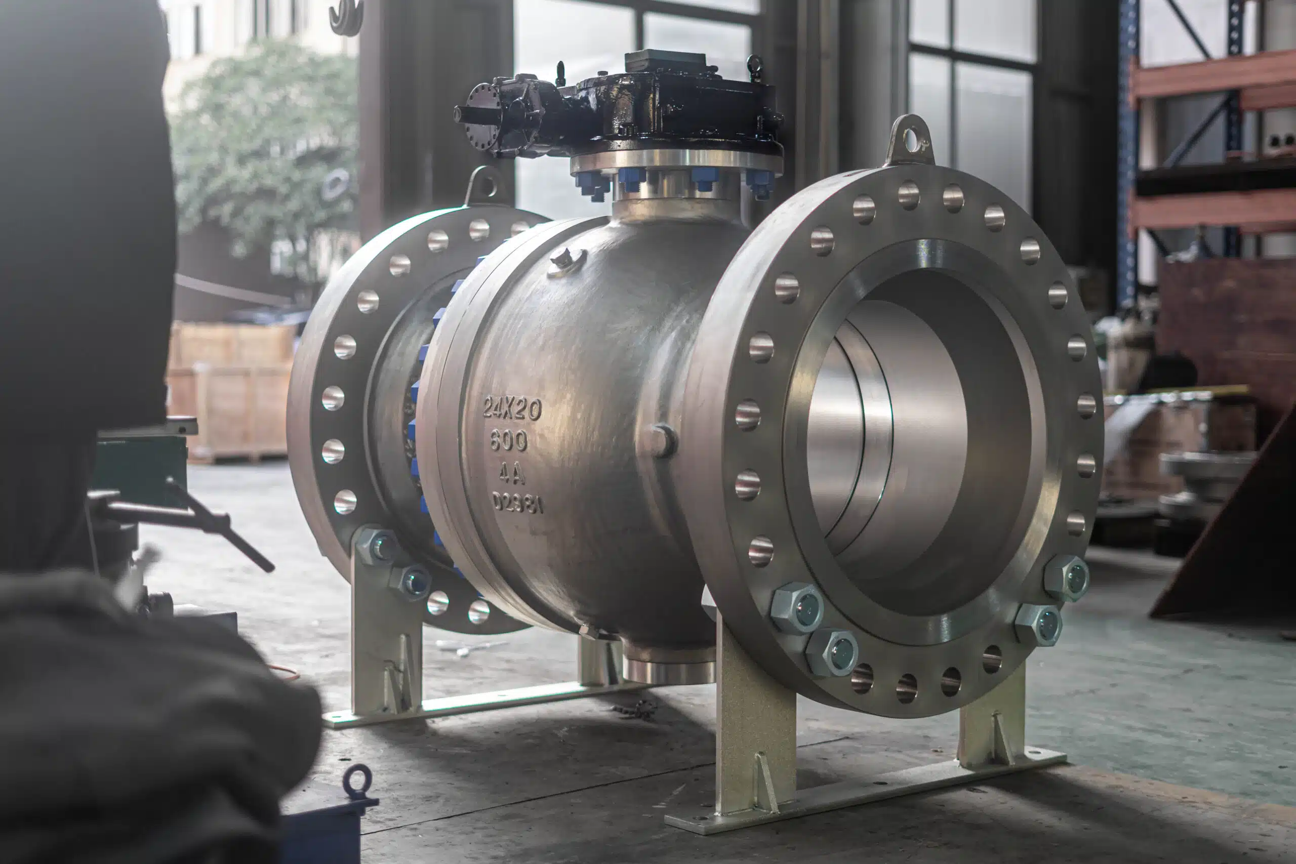
Split body ball valves are industrial shut-off valves built with a body that is divided into two or more bolted sections around the ball and seats. This construction makes the internal parts easier to inspect, maintain, or replace compared with body designs where the pressure-containing assembly is less accessible.
For engineers and industrial buyers, the key question is not only “what is a split body ball valve?” The more useful question is: when does the split-body construction improve maintenance access, sealing reliability, and service fit enough to justify the valve selection?
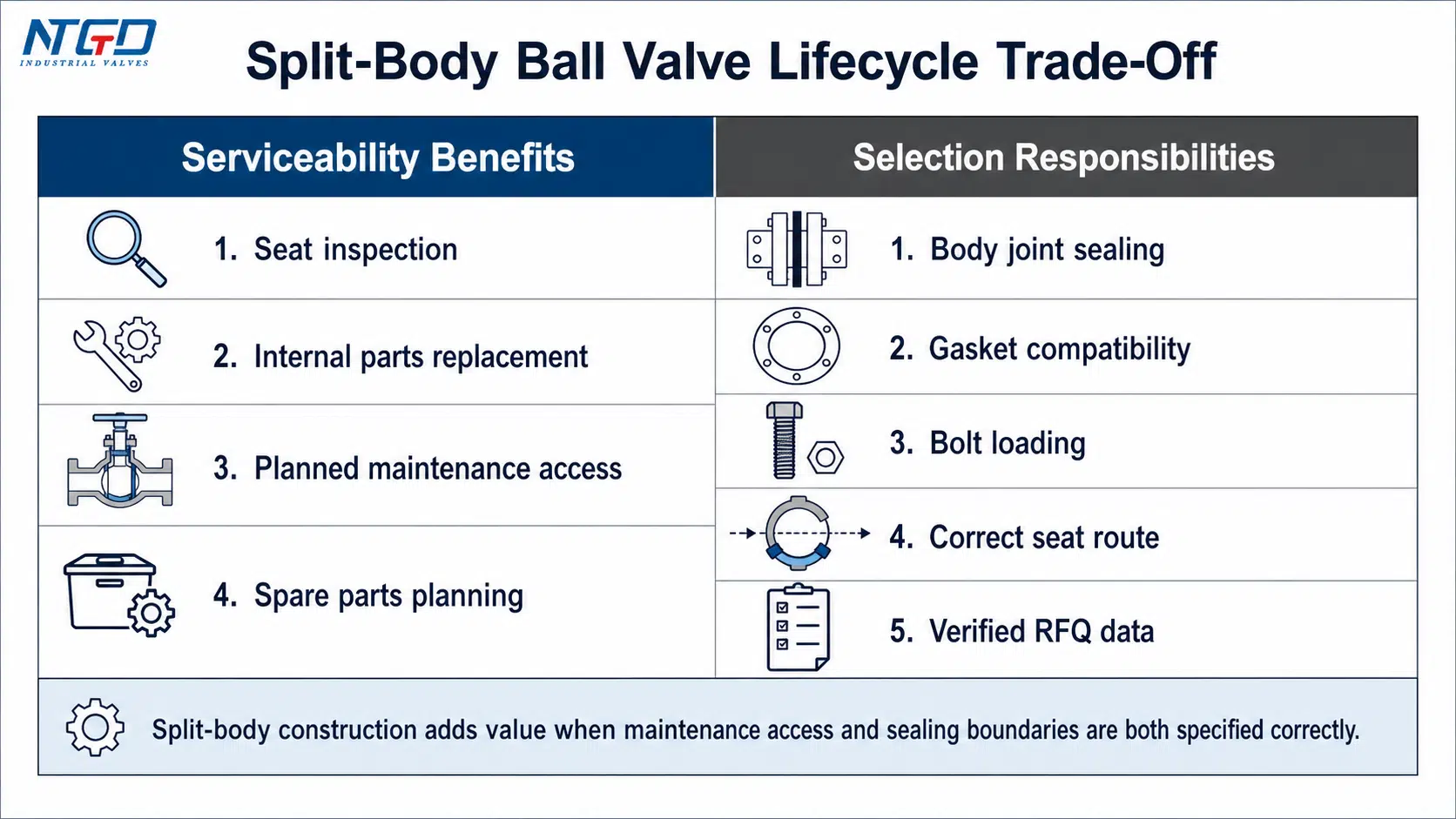
The answer depends on a trade-off. A split-body ball valve can make seat inspection, gasket replacement, and internal maintenance more practical, but it also requires the buyer to manage bolted body joints, body gaskets, bolt loading, and sealing compatibility under the actual pressure, temperature, and media conditions.
A good selection should confirm:
- Whether the split-body construction fits the maintenance strategy.
- Whether floating or trunnion construction is more suitable for the size, pressure, and torque requirement.
- Whether the seat, packing, and body gasket materials match the medium and temperature.
- Whether the valve requires full bore, reduced bore, fire-safe design, low-emission packing, anti-static design, DBB / DIB, or cavity relief.
- Which standards, tests, and RFQ fields must be confirmed before quotation.
What Are Split-Body Ball Valves?
A split body ball valve is a ball valve whose pressure-containing body is manufactured in separate sections and then bolted together. The ball, seats, stem, packing, and sealing parts are assembled inside the body. The valve still works as a quarter-turn ball valve, but the body construction gives maintenance teams a more accessible route to internal components.
In simple terms, the “split body” describes the body construction, not a different flow-control principle. The valve still opens when the bore through the ball aligns with the pipeline and closes when the ball rotates 90 degrees. What changes is the way the valve body is assembled, serviced, and sealed.
Definition of a Split-Body Ball Valve
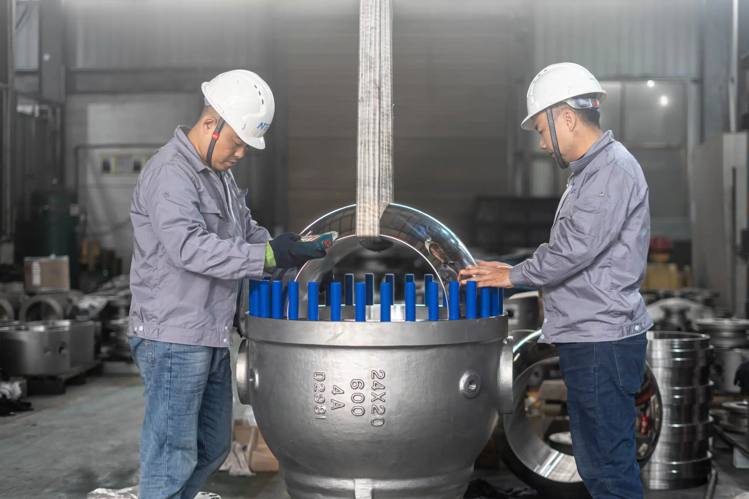
A split-body ball valve normally has a two-piece or three-piece body design. In many industrial flanged designs, the body sections are bolted together around the ball and seats. This construction allows the internal sealing parts to be assembled accurately and gives maintenance teams a clearer path for inspection or replacement.
The split-body arrangement may be used with:
- Floating ball designs.
- Trunnion-mounted ball designs.
- Full bore or reduced bore flow paths.
- Soft seated, resilient seated, or metal seated constructions.
- Manual, gear-operated, pneumatic, electric, or hydraulic actuation.
- Flanged, welded, or other industrial end connections, depending on the design.
The exact configuration depends on size, pressure class, medium, temperature, leakage expectations, maintenance access, and project specification.
Why the Split-Body Construction Matters
The main value of split-body construction is serviceability. In many industrial plants, the valve body design affects how easily technicians can access the ball, seats, body gasket, and stem sealing area during inspection or repair.
This matters when:
- Downtime must be planned carefully: split-body construction can make scheduled inspection and internal parts replacement more predictable than less accessible body designs.
- Seat wear is expected over time: access to the ball and seats makes it easier to confirm whether sealing damage is caused by normal wear, abrasive particles, chemical attack, or operating conditions.
- The medium may attack sealing materials: seats, packing, and body gaskets must be checked as a system, not as isolated parts.
- The valve is installed in a critical isolation line: the body design must support shut-off reliability while still allowing practical inspection during maintenance windows.
- Spare parts planning matters: seats, gaskets, packing, and stem sealing parts should be selected and documented before the valve enters service.
The same construction also creates a responsibility. Bolted body joints and body gaskets are pressure-containing sealing boundaries. In corrosive, high-temperature, cyclic, or vibration-prone service, gasket compatibility, bolt loading, body joint design, and inspection procedure become part of the selection decision.
What This Article Covers—and What It Does Not Cover
This article focuses on split-body ball valves for industrial applications. It explains construction, working principle, floating versus trunnion routes, seat and seal boundaries, comparison with other body designs, application fit, and RFQ-ready specification fields.
It does not try to cover every ball valve type. It also does not treat split body ball valves as a product catalog item or a price-based selection. The purpose is to help engineers and industrial buyers understand where the split-body design fits and what must be confirmed before specifying or requesting a quotation.
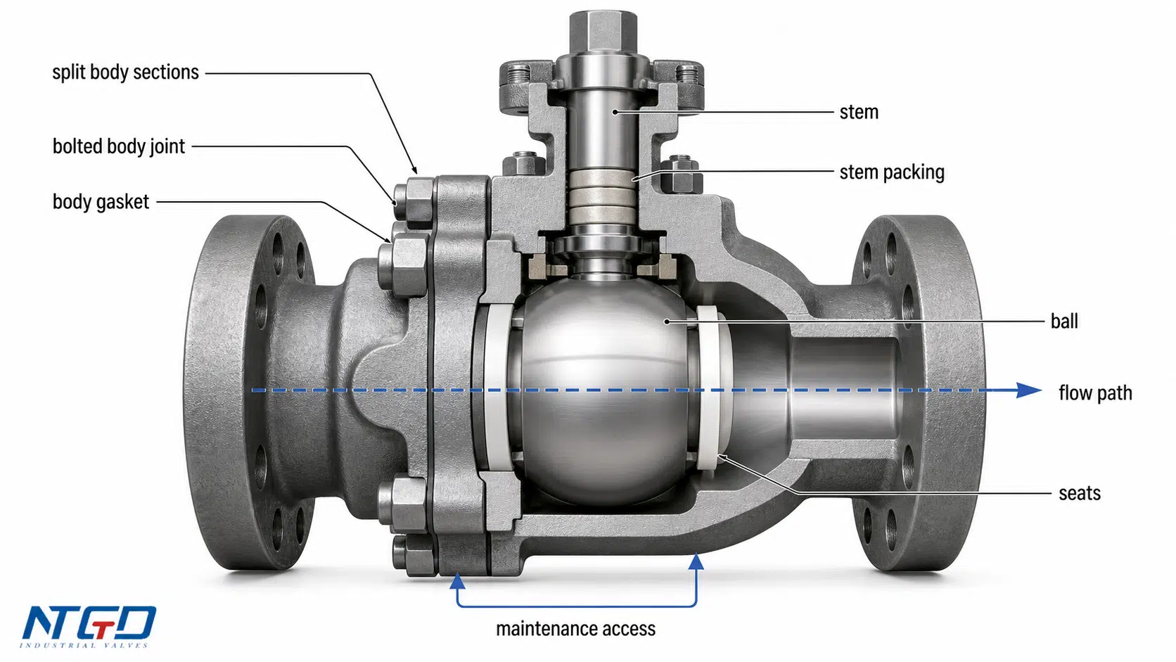
Split-Body Ball Valve Design: Body Construction and Key Components
The split body ball valve design should be understood as a pressure-containing assembly. The body sections, bolts, gasket, ball, seats, stem, and packing all influence sealing performance and maintenance access.
A basic parts list is not enough for selection. The important point is how each component affects service life, leakage risk, pressure containment, and repair planning.
Two-Piece, Three-Piece, and Multi-Piece Body Construction
Split-body ball valves are usually built as two-piece or three-piece body designs.
A two-piece split-body ball valve typically has one main body section and one end piece or side-entry section bolted together. This design is common in many flanged industrial ball valves where a compact, pressure-rated, serviceable body is required.
A three-piece split-body ball valve usually has a central body section with two end connections. Depending on the design and installation, this arrangement can make access to the center section more practical during maintenance.
A multi-piece body design may be used in specialized constructions where the pressure class, size, seat system, or assembly method requires it. More body pieces do not automatically mean a better valve. Each additional body joint must be sealed, bolted, inspected, and maintained correctly.
The body construction should be evaluated by maintenance access, joint count, gasket control, installation space, pressure class, and service severity together. The right split-body ball valve design is not the design with the most pieces; it is the design whose access route and sealing boundaries match the service.
Body Joint, Bolts, and Gasket Sealing
The body joint is one of the most important design areas in a split-body ball valve. It must maintain pressure containment while allowing the valve body to be assembled around the internal parts.
Key points to confirm include:
- Body joint design and gasket type.
- Bolt material and tightening requirements.
- Compatibility between gasket material and process medium.
- Pressure and temperature limits of the body seal.
- Whether the valve will see thermal cycling, vibration, corrosive service, or repeated maintenance.
In clean, stable service, the body joint may not receive much attention after installation. In severe service, it can become one of the main inspection points. A good split-body design should make maintenance easier without creating avoidable leakage risk at the body joint.
Key Components and Their Design Relevance
| Component | Function | Why It Matters for Selection |
|---|---|---|
| Body | Contains pressure and supports internal parts | Body material and split construction determine pressure class, corrosion resistance, and access to internal parts during maintenance |
| Body joint / gasket | Seals the bolted body connection | A primary leakage path if gasket material, joint design, or bolt loading is mismatched to pressure, temperature, or media |
| Body bolts | Clamp the body sections together | Incorrect bolt material, tightening, or inspection can reduce body joint integrity under thermal cycling or vibration |
| Ball | Rotates to open or close the flow path | Floating or trunnion support affects torque, seat loading, sealing behavior, and pressure suitability |
| Seats | Seal against the ball | Seat material determines shut-off performance, temperature limit, chemical compatibility, and wear resistance |
| Stem | Transfers torque from actuator or handle to ball | Stem design affects operation, blow-out prevention, fugitive emission control, and actuator torque transfer |
| Packing | Seals around the stem | Packing selection affects external leakage risk, emission control, and maintenance frequency |
| End connection | Connects valve to pipeline | Flanged, welded, or threaded ends affect installation, disassembly route, and maintenance access |
| Actuation interface | Allows manual or automated operation | Gear, pneumatic, electric, or hydraulic actuation must match torque demand, operating speed, and control method |
How the Design Supports Inspection and Seat Replacement
The split-body design gives maintenance teams a defined route to internal parts. When the valve is isolated, depressurized, drained, and removed or accessed according to the manufacturer’s maintenance procedure, the body sections can be opened to inspect the ball, seats, seals, and gasket surfaces.
This is useful when the service is expected to cause:
- Seat wear.
- Seal aging.
- Stem packing deterioration.
- Deposits around the ball.
- Corrosion at sealing surfaces.
- Gasket replacement during shutdowns.
The design does not eliminate maintenance work. It makes maintenance planning more predictable when the valve is selected, installed, and serviced correctly.
How Split-Body Ball Valves Work
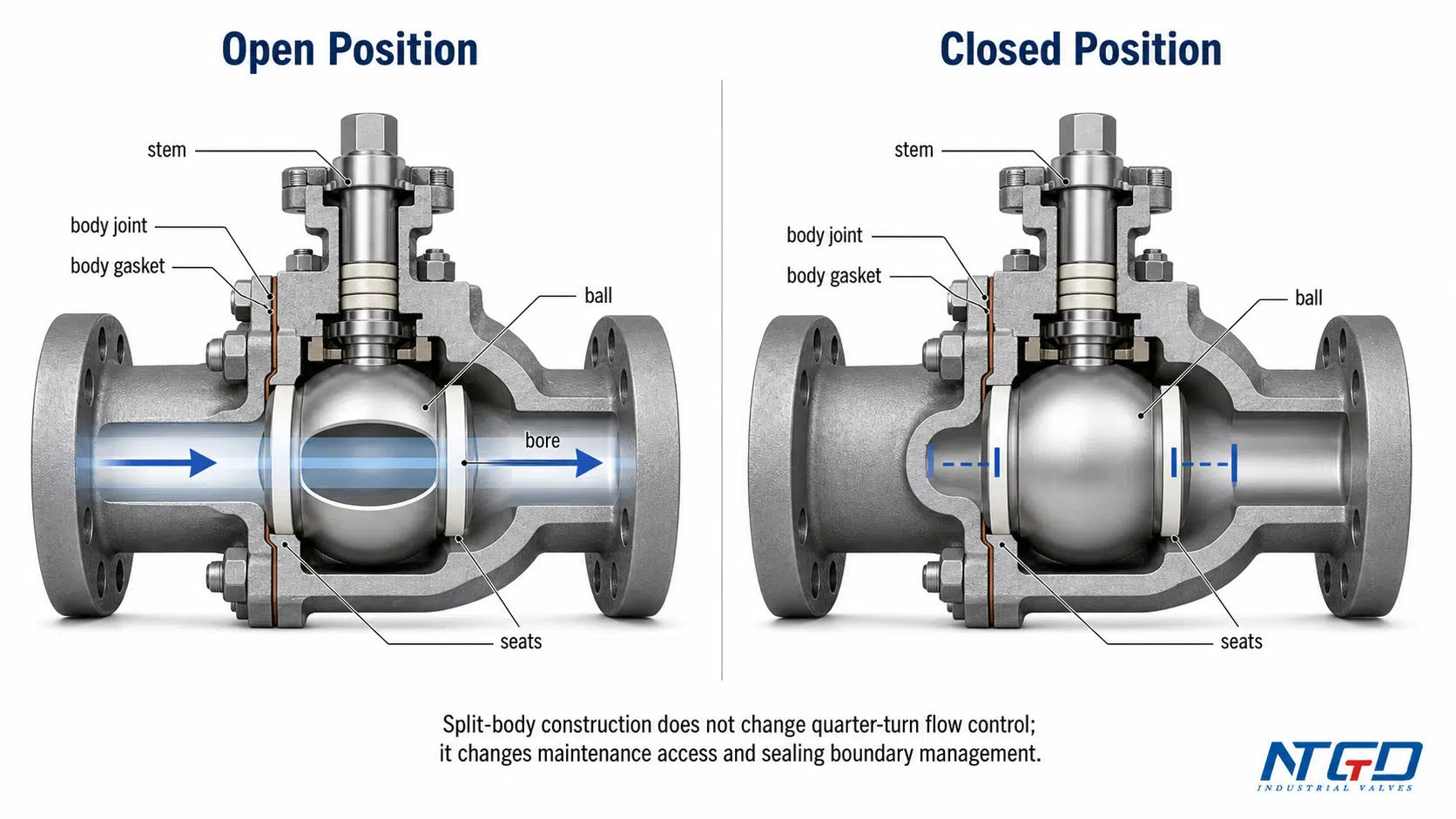
A split-body ball valve works by rotating a ball inside the valve body. The ball has a central bore. When the bore aligns with the pipeline, fluid passes through. When the ball turns 90 degrees, the solid side of the ball blocks the flow.
This quarter-turn action is the same basic working principle used by many ball valves. The split-body construction does not change the open-close mechanism. Instead, it changes how the valve is assembled, how the sealing boundaries are arranged, and how internal parts may be inspected or replaced.
Quarter-Turn Flow Control
Ball valves are valued because they can provide fast shut-off with a simple quarter-turn movement. In the open position, the flow path through the ball is aligned with the pipe. In the closed position, the ball blocks the path.
For isolation service, this gives operators a clear open or closed position. For automated systems, the same quarter-turn movement can be driven by pneumatic, electric, or hydraulic actuators.
Split-body ball valves are normally used for shut-off and isolation, not for continuous throttling. Operating a standard ball valve at a partially open position for long periods can expose the seats and ball edge to concentrated wear, vibration, and erosion.
Flow Path, Full Bore, and Reduced Bore Considerations
Split-body ball valves can be designed with full bore or reduced bore flow paths.
| Bore Type | Flow Characteristic | Selection Relevance |
|---|---|---|
| Full bore | Bore size is close to the pipe bore | Lower pressure drop, easier pigging in suitable pipeline designs, and better fit where flow restriction must be minimized |
| Reduced bore | Bore is smaller than the pipe bore | More compact and often lower cost, but creates more pressure drop |
| Piggable bore | Designed to allow pipeline pig passage where required | Important for certain oil, gas, or long-distance pipeline services |
A full bore design is not automatically required. It should be specified when pressure drop, cleaning, pigging, or flow capacity makes it necessary. For utility service or smaller lines, reduced bore may be acceptable if the system design allows it.
Floating Ball Sealing Logic
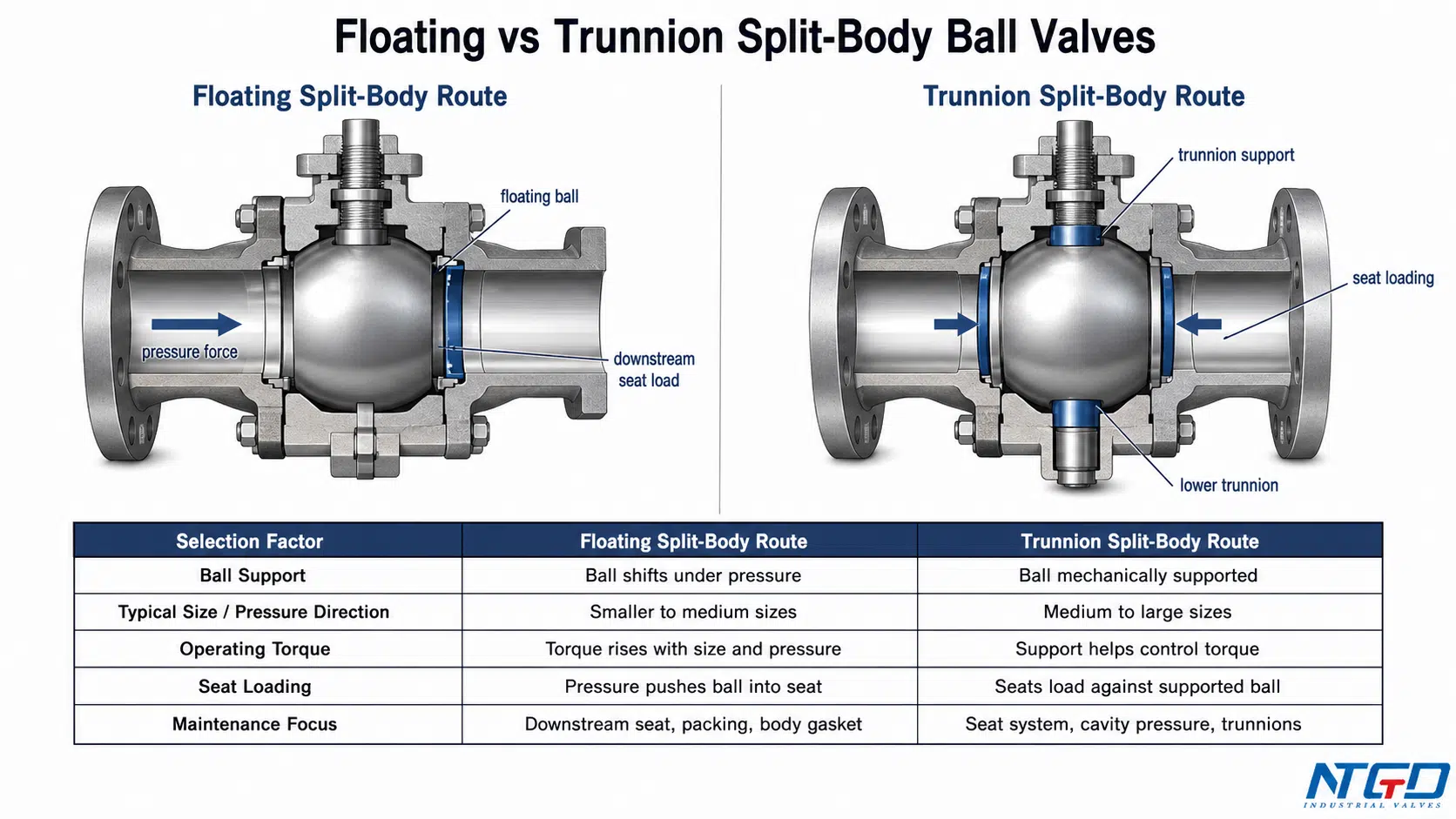
Many split-body ball valves use a floating ball design. In this construction, the ball is not rigidly fixed by trunnions. Line pressure pushes the ball toward the downstream seat, helping create a tight seal.
Floating ball designs are widely used in smaller and medium-size ball valves because they are relatively simple, compact, and effective for many shut-off services. However, as size and pressure increase, the force on the ball and seats also increases. This can raise operating torque and seat stress.
In a split-body design, this sealing logic also affects maintenance feedback. When the body is opened during inspection, the downstream seat and sealing contact area can be checked for wear, deformation, deposits, or surface damage. This helps confirm whether the sealing system is holding up under the actual service.
That is why larger or higher-pressure split-body ball valves may use trunnion-mounted construction instead.
How Split-Body Access Changes Maintenance, Not Basic Flow Control
The most common misunderstanding is that a split-body ball valve works differently from other ball valves during normal operation. It does not. The flow is still controlled by ball rotation.
The difference appears during inspection and maintenance. The split-body construction gives access to the internal assembly. Depending on the design and installation, technicians may inspect the seats, ball surface, packing condition, body gasket, and sealing contact areas more directly than with less serviceable body constructions.
This creates a maintenance feedback loop. The user can connect actual wear patterns to media condition, pressure differential, cycling frequency, actuator sizing, and seat material. That is the practical value of split-body construction: not a different open-close principle, but a more serviceable pressure-containing assembly.
Floating vs Trunnion Split-Body Ball Valves
Split-body ball valves can be built with either floating ball or trunnion-mounted ball construction. This choice affects operating torque, seat loading, pressure suitability, size range, and pipeline isolation performance.
The floating vs trunnion ball valve route should be chosen before the RFQ is finalized. If the buyer specifies only “split body ball valve,” the supplier may not have enough information to select the right internal support design.
Floating Split-Body Ball Valves
In a floating split-body ball valve, the ball is supported mainly by the stem and seats. Line pressure pushes the ball against the downstream seat to create sealing force.
Floating designs are often considered when:
- Valve size is small to medium.
- Pressure is moderate for the selected design.
- A compact structure is preferred.
- Torque requirements remain manageable.
- The medium is clean enough to avoid severe seat damage.
The main advantage is simplicity. The main limitation is that pressure acting on the ball increases seat loading and operating torque. In larger or higher-pressure applications, this can make operation more difficult and increase seat wear.
Trunnion-Mounted Split-Body Ball Valves
In a trunnion-mounted split-body ball valve, the ball is supported by trunnions. The ball position is more controlled, and the seats move or load against the ball depending on the design. This reduces the torque required to operate large or high-pressure valves.
Trunnion-mounted split-body ball valves are commonly considered for:
- Larger pipeline sizes.
- Higher pressure classes.
- Oil and gas isolation.
- Long-distance pipelines.
- Critical shut-off service.
- Applications where lower operating torque is required.
Trunnion designs may also include advanced seat arrangements, body cavity relief, drain and vent connections, DBB or DIB configurations, and fire-safe features when required by the service.
These features should not be assumed. They must be specified and confirmed in the RFQ.
Pressure, Size, Torque, and Seat Loading Differences
| Selection Factor | Floating Split-Body Ball Valve | Trunnion Split-Body Ball Valve |
|---|---|---|
| Ball support | Ball shifts slightly under pressure | Ball is mechanically supported |
| Typical size range | Smaller to medium sizes | Medium to large sizes |
| Operating torque | Torque and seat stress increase more as pressure and size increase | Mechanical support helps manage torque in larger or higher-pressure service |
| Seat loading | Line pressure pushes ball into seat | Seat design controls sealing load against a supported ball |
| Pipeline isolation | Suitable for many general services | Often preferred for critical pipeline isolation |
| Maintenance focus | Downstream seat wear, stem packing, body gasket | Seat system, cavity pressure, trunnion support, sealing system |
The core trade-off is direct: floating designs are simpler, but pressure and size place
more load on the ball and seats. Trunnion designs manage those loads mechanically, but they shift complexity toward the seat system, cavity pressure management, testing requirements, and project specification.
When Each Route Is Usually Considered
A floating design is usually more suitable when the valve is smaller, the pressure is within a manageable range, and the operating torque does not create actuator or handle problems.
A trunnion design becomes more relevant when the valve is large, pressure is high, shut-off duty is critical, or pipeline isolation requires more controlled sealing and lower operating torque.
The body may be split in both designs. The internal ball support route is a separate decision from the body construction. For RFQ work, “split body ball valve” should be followed by the required support route: floating or trunnion-mounted.
Seat, Seal, and Leakage Boundary in Split-Body Ball Valves
The sealing performance of a split-body ball valve depends on more than the ball and seat. A complete leakage boundary includes the ball-seat interface, stem packing, body gasket, and any drain, vent, or auxiliary sealing points.
This is why seat and seal selection should be treated as a core engineering decision, not a small material detail.
Soft Seat, Resilient Seat, and Metal Seat Routes
Soft seated or resilient seated split-body ball valves are used where tight shut-off is required and the temperature, pressure, and medium are compatible with the seat material. Common seat routes may include PTFE-based or reinforced polymer materials, depending on the manufacturer and service.
Metal seated split-body ball valves are considered where soft seats may not survive the service. These services may include higher temperature, abrasive media, frequent cycling, or conditions where erosion and seat damage are expected.
| Seat Route | Typical Strength | Main Selection Risk |
|---|---|---|
| Soft / resilient seat | Tight shut-off and lower operating torque in many clean services | Susceptible to deformation, extrusion, chemical attack, or rapid wear if pressure differential, temperature, or solids exceed the seat material limits |
| Reinforced polymer seat | Better strength than basic soft seat in some services | Still limited by media compatibility, temperature, abrasive wear, and long-term compression behavior |
| Metal seat | Better fit for heat, abrasion, frequent cycling, or severe service | May require higher torque, tighter surface control, specialized coatings, and verified leakage expectations |
| Fire-safe seat design | Maintains a defined secondary sealing path after soft seat damage in fire-tested designs | Must be specified and verified by the applicable fire-safe test requirement |
The right soft-seated vs metal-seated ball valve route depends on medium, temperature, pressure differential, cycling frequency, leakage requirement, and expected solids or deposits.
Ball-Seat Seal, Stem Packing, and Body Gasket
A split-body ball valve has several important sealing zones:
| Sealing Zone | What It Controls | Why It Matters |
|---|---|---|
| Ball-seat seal | Internal shut-off through the valve | Determines whether the valve can isolate upstream and downstream sides as required |
| Stem packing | External leakage around the stem | Important for safety, emissions, maintenance, and actuator interface reliability |
| Body gasket | External leakage at the bolted body joint | Critical in split-body construction because the body joint is a pressure-containing seal |
| Drain / vent connections | Controlled release or testing points in some designs | Important for DBB/DIB or pipeline service when specified |
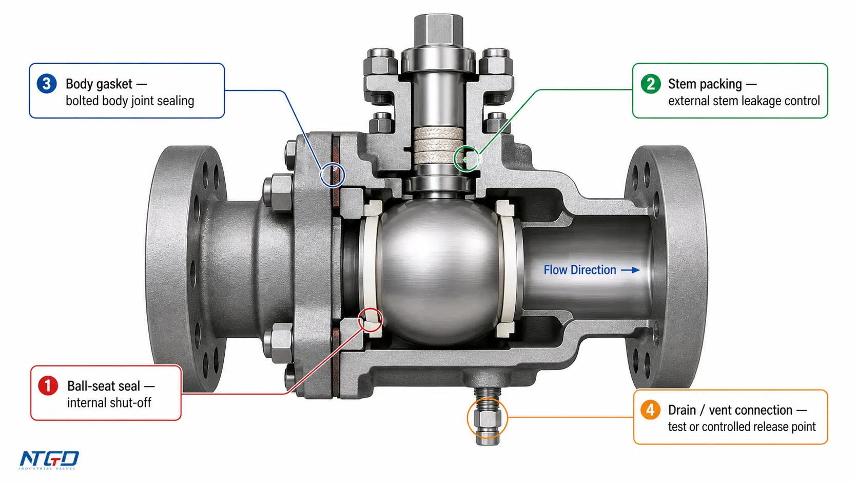
If a valve leaks, the failure path matters. Seat leakage is not the same as stem leakage. Body gasket leakage is not the same as internal passing. Each issue has a different cause, inspection method, and maintenance action.
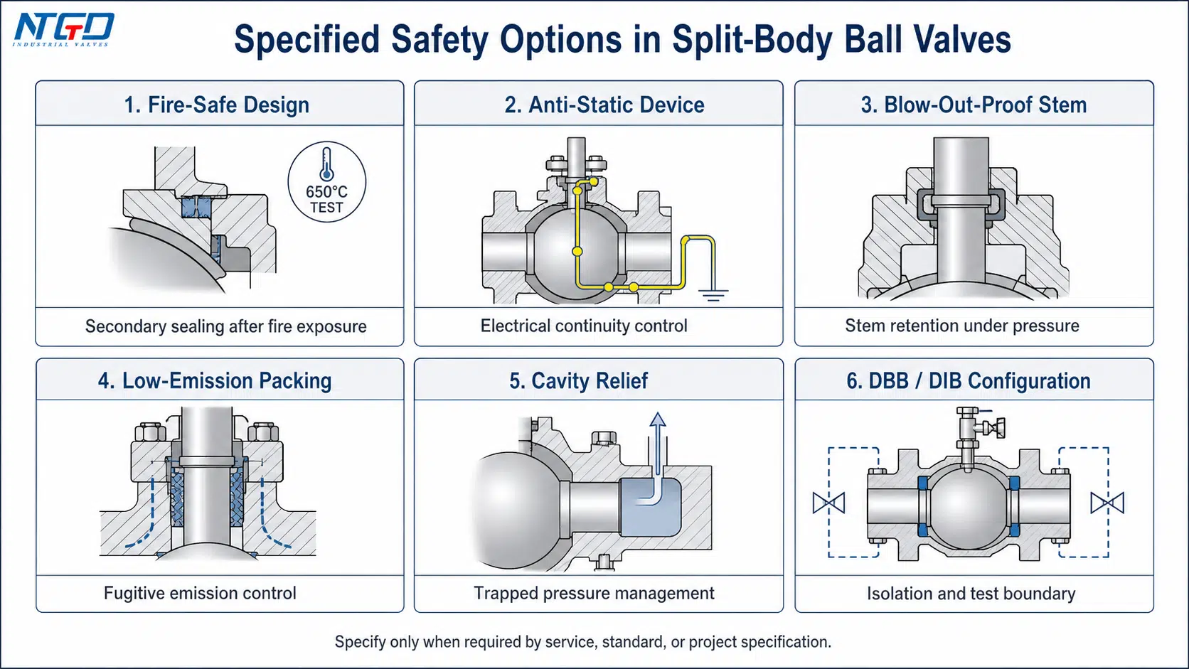
Fire-Safe, Low-Emission, and Anti-Static Design Options
Some split-body ball valves may require additional safety features depending on the service.
Common options include:
- Fire-safe ball valve design: Used where the valve must maintain a defined level of sealing after exposure to fire conditions.
- Anti-static device: Helps provide electrical continuity between ball, stem, and body where static discharge risk must be controlled.
- Blow-out-proof stem: Helps prevent stem ejection under pressure in properly designed valves.
- Low-emission packing: Used where fugitive emissions from the stem sealing area must be controlled, especially when fugitive emission testing or project qualification requirements apply.
- Cavity relief: Relevant in some designs where trapped pressure in the body cavity must be relieved safely.
- DBB / DIB configurations: Used in certain pipeline or isolation services, especially in trunnion-mounted designs.
These should be treated as specified design requirements. They are not automatic features of every split-body ball valve.
Common Leakage or Wear Risks to Check
Before selecting a split-body ball valve, check the likely wear and leakage paths:
- Abrasive particles: solids can damage soft seats and create internal passing even when the valve closes fully.
- High temperature or thermal cycling: unsuitable seats, packing, or body gaskets may lose sealing force, while bolt loading at the split body joint may need closer inspection.
- Chemical attack: incompatible media can damage seats, packing, or body gaskets, turning a material mismatch into an external leakage risk.
- Frequent cycling: repeated operation can accelerate seat wear, especially when the pressure differential or media condition is severe.
- Incorrect actuator sizing: insufficient torque can cause incomplete operation, while excessive torque can damage seats or stem components.
- Long-term throttling: partially open operation can erode the ball edge and seats, weakening shut-off performance.
A valve that looks correct by size and pressure class may still fail early if the seat, packing, gasket, and media conditions are not matched.
Split-Body vs Other Ball Valve Body Designs
Split-body construction is one body design route among several ball valve body styles. Comparing it with other designs helps clarify when the split-body route adds value and when another construction may be more suitable.
The comparison should focus on body access, leak paths, maintenance strategy, pressure requirements, and lifecycle cost—not only initial purchase price.
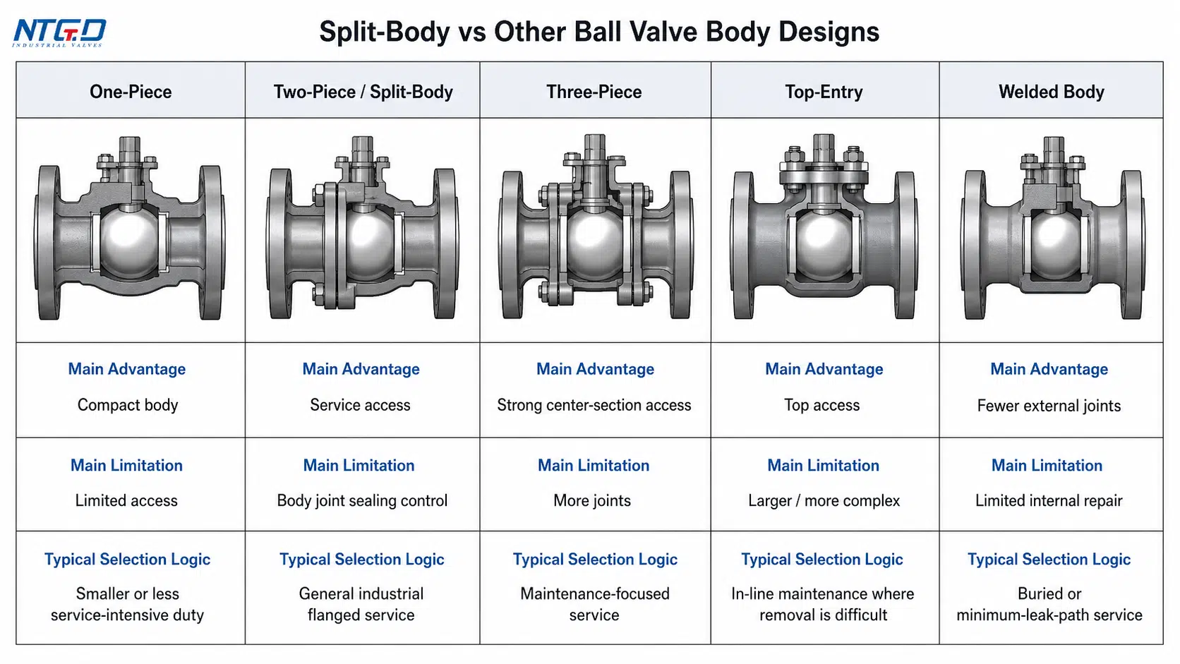
Split-Body vs One-Piece Ball Valves
A one-piece ball valve has a more compact body with fewer body joints. This can reduce external leak paths, but internal access is more limited. One-piece designs are often used in smaller or less service-intensive applications.
A split-body ball valve is more serviceable because the body can be opened according to the manufacturer’s maintenance procedure. This makes it more suitable when seat inspection, part replacement, or long-term maintenance planning matters.
Split-Body vs Top-Entry Ball Valves
A top-entry ball valve is designed so internal parts can be accessed from the top of the valve. This can be useful where removing the valve from the pipeline is difficult or where in-line maintenance is required.
A split-body ball valve may be easier to manufacture across many sizes and configurations, and it is widely used in flanged industrial service. However, maintenance access depends on the exact body design, installation, and pipeline layout. It is not accurate to say every split-body valve must be fully removed or that every top-entry valve is automatically easier to maintain.
Split-Body vs Welded Body Ball Valves
A welded body ball valve has fewer external body joints. This can be valuable in buried service, long-distance pipelines, or services where external leakage paths must be minimized. The trade-off is that internal maintenance access is more limited.
A split-body design offers better access to internal parts, but the body joint and gasket must be managed carefully. For services where maintenance access is important, split-body construction may be preferred. For services where minimum external joints are the main priority, welded body construction may be considered.
What the Comparison Means for Maintenance and Service Conditions
| Body Design | Main Advantage | Main Limitation | Typical Selection Logic |
|---|---|---|---|
| One-piece | Compact, fewer body joints | Limited internal access | Smaller or less service-intensive applications |
| Two-piece / split-body | Better service access than one-piece | Body joint requires sealing control | General industrial flanged service, repairable construction |
| Three-piece | Strong maintenance access in many designs | More joints and assembly requirements | Services where center-section access is valuable |
| Top-entry | Top access to internal parts | Larger and often more complex design | In-line maintenance where removal is difficult |
| Welded body | Fewer external body joints | Limited internal repair access | Buried pipelines or services prioritizing external sealing integrity |
The selection starts with one practical question: is internal access for maintenance a primary lifecycle requirement? If yes, split-body and top-entry designs deserve closer review. If no, one-piece or welded body designs may become more relevant. The final decision should compare access route, total joint count, installation layout, leakage risk, and maintenance plan.
Industrial Applications and Selection Fit
Split body ball valves are used across many industrial sectors because they combine shut-off performance with serviceable construction. The best fit is not defined by industry name alone. It is defined by pressure, temperature, medium, maintenance access, leakage expectations, and operating frequency.
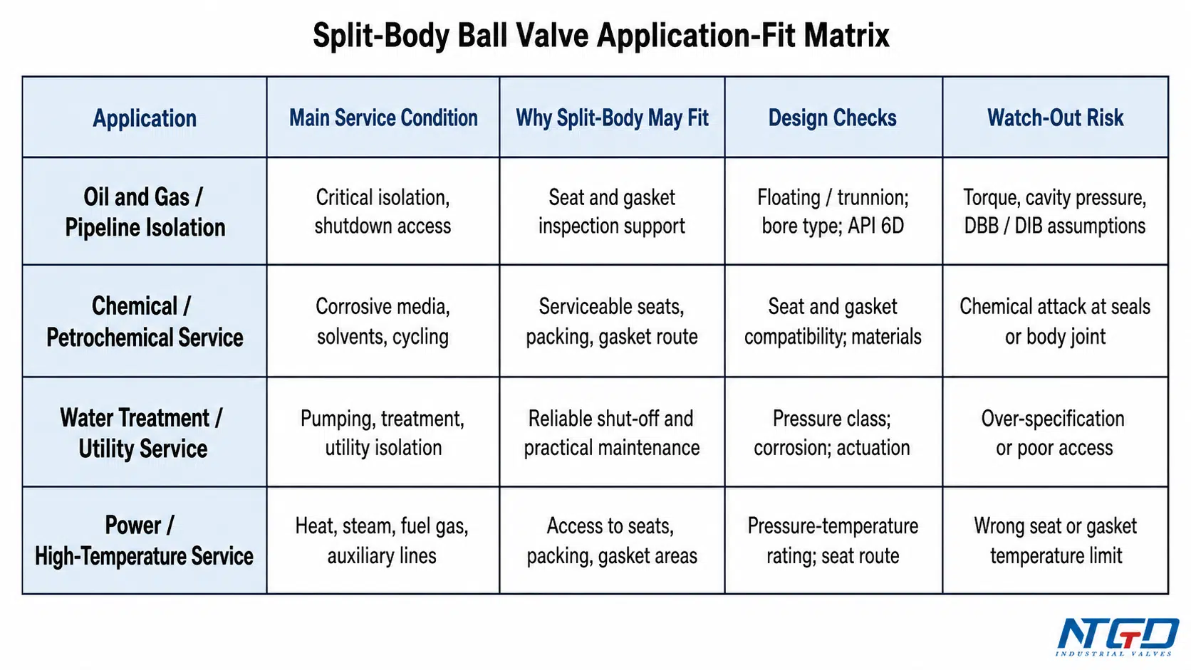
Oil and Gas / Pipeline Isolation
In oil and gas pipeline isolation, the value of a split-body ball valve is strongest when scheduled shutdowns are the main opportunity for inspection and internal intervention. Predictable access to seats, seals, and body gasket areas can support maintenance planning in critical pipeline and process isolation service.
Design points to confirm include:
- Floating or trunnion construction.
- Full bore, reduced bore, or piggable bore requirement.
- API 6D requirement when applicable.
- Fire-safe, anti-static, DBB / DIB, drain / vent, or cavity relief requirement.
- Material compatibility for sour service or corrosive service.
For pipeline isolation, trunnion-mounted split-body ball valves are often considered when size, pressure, and torque requirements exceed the practical range of floating designs.
Chemical and Petrochemical Service
Chemical-service ball valve selection requires careful review of body material, seat material, packing, and gasket compatibility. The valve may face corrosive fluids, solvents, temperature swings, or media that can damage soft sealing materials.
Design points to confirm include:
- Body and trim material.
- Seat material compatibility.
- Stem packing and body gasket material.
- Temperature and pressure limits.
- Fire-safe, low-emission, metal seat, or special coating requirement.
A split-body valve may be useful because internal parts can be inspected during shutdowns. However, the body joint and gasket must be selected for the same chemical environment as the rest of the valve. If the gasket route is weaker than the body material route, the bolted joint can become the limiting point.
Water Treatment and Utility Service
Water treatment and utility systems may use split-body ball valves for isolation in pumping stations, treatment plants, and distribution systems. The service may include treated water, raw water, or chemicals such as chlorine dosing lines, depending on the system.
Design points to confirm include:
- Pressure class.
- Body and seat material.
- Corrosion resistance.
- Full bore or reduced bore.
- Actuation method.
- Maintenance access in installed position.
In many water services, the main value is reliable shut-off and practical maintenance. Severe high-pressure or high-temperature features may not be necessary unless the system requires them.
Power and High-Temperature Service
Power generation and high-temperature industrial services require careful review of pressure-temperature rating, seat route, packing, and body material. Steam, fuel gas, cooling water, condensate, and auxiliary systems may have very different valve requirements.
Design points to confirm include:
- ASME pressure-temperature rating.
- Body material at operating temperature.
- Seat and seal temperature limits.
- Packing and body gasket compatibility.
- Fire-safe or low-emission requirement where applicable.
- Whether metal seated construction is needed.
The split-body design can support maintenance access, but only if the seat, gasket, and packing materials match the service temperature and operating cycle.
When Split-Body Ball Valves May Not Be the Best Choice
Split-body ball valves are not the correct answer for every service.
They may not be the best choice when:
- The valve will be used for continuous throttling: partially open operation can concentrate velocity across the ball edge and seats, causing erosion and loss of shut-off performance.
- The service contains heavy abrasive solids without a suitable seat and coating route: the split-body design may make repair easier, but it does not prevent seat damage if the sealing route is wrong.
- The installation cannot accommodate the valve’s weight or body size: large flanged split-body valves may require more space, support, and handling planning.
- A welded body is preferred to reduce external body joints: in buried or minimum-leak-path service, fewer external joints may matter more than internal access.
- Top-entry access is required: if the valve cannot be removed or opened from the side, split-body maintenance access may not match the installation reality.
- A sanitary valve design is required for hygienic processing: standard industrial split-body ball valves should not be assumed suitable for hygienic service.
- The buyer cannot define pressure, temperature, media, and sealing requirements clearly: incomplete service data can lead to the wrong seat, gasket, ball support, or bore selection.
The strongest selection is not “split body is better.” The stronger selection logic is: split-body construction is valuable when serviceability, body access, and internal component replacement matter enough to justify the design and when the sealing boundaries are properly specified.
Standards, RFQ Data, and Final Specification Checklist
Standards and RFQ fields should not be treated as a generic list. They are part of the technical boundary that tells the supplier how the valve must be designed, tested, and documented.
For split-body ball valves, the RFQ should define the service conditions first, then the valve construction and testing requirements.
Standards Commonly Checked for Split-Body Ball Valves
The applicable standards depend on industry, pressure class, end connection, fire-safe requirement, emission requirement, and project specification.
| Standard / Requirement | Why It May Matter | RFQ Relevance |
|---|---|---|
| API 6D | Pipeline valve requirements in oil and gas service | Relevant when pipeline isolation or project specification requires it |
| API 608 | Metal ball valve requirements | Relevant for many industrial flanged ball valves |
| ASME B16.34 | Pressure-temperature rating and valve body design basis | Helps confirm pressure class and material suitability |
| ASME B16.5 | Flanged end dimensions and ratings | Relevant when flanged connections are specified |
| API 607 / API 6FA | Fire-safe testing | Relevant when fire-safe service is required |
| ISO 15848 | Fugitive emission performance | Relevant when low-emission packing is required |
| NACE / ISO 15156 | Sour service material requirements | Relevant when H₂S or sour service is present |
| ISO 5208 or project leakage test requirement | Pressure and leakage testing reference | Relevant for acceptance testing and leakage class confirmation |
These standards should be confirmed according to the project specification. Do not assume that every split-body ball valve must meet every listed standard.
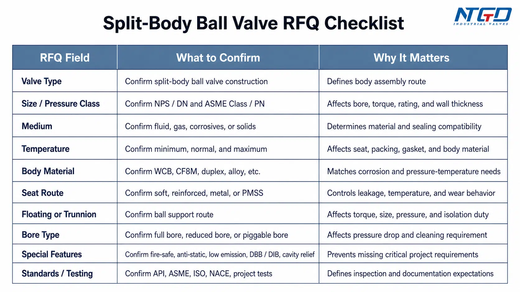
RFQ Fields Engineers Should Confirm
A complete RFQ should give the supplier enough information to support industrial valve selection, including the correct body, ball support, seat, seal, and test requirements.
| RFQ Field | What to Specify | Why It Matters |
|---|---|---|
| Valve type | Split body ball valve | Confirms body construction route |
| Size | NPS / DN | Affects bore, torque, weight, and end connection |
| Pressure class | ASME Class / PN / design pressure | Determines body rating and wall thickness requirement |
| Medium | Fluid or gas, including corrosive or solid content | Determines material and seat compatibility |
| Temperature | Minimum, normal, and maximum | Affects seat, packing, gasket, and body material |
| Body material | WCB, CF8M, duplex, alloy, etc. | Must match corrosion and pressure-temperature needs |
| Ball / stem material | Stainless steel, plated, coated, alloy, etc. | Affects corrosion, wear, and torque |
| Seat route | Soft, reinforced, resilient, metal, PMSS | Determines leakage, temperature, and wear behavior |
| Ball support | Floating or trunnion | Affects pressure, size, torque, and sealing logic |
| Bore type | Full bore, reduced bore, piggable if needed | Affects pressure drop and pipeline cleaning |
| End connection | Flanged, welded, threaded, etc. | Affects installation and maintenance |
| Actuation | Lever, gear, pneumatic, electric, hydraulic | Must match torque and operation requirements |
| Special features | Fire-safe, anti-static, low emission, DBB/DIB, cavity relief | Prevents missing critical project requirements |
| Testing / standards | API, ASME, ISO, NACE, project-specific tests | Defines inspection and documentation expectations |
Final Fit-Check Before Selection or Quotation
Before finalizing a split body ball valve selection, use the RFQ as an engineering review checklist:
- Confirm that the body construction matches the planned maintenance strategy; otherwise, the expected serviceability may not be available in the installed position.
- Confirm floating or trunnion construction before quotation; leaving the ball support route undefined can lead to incorrect torque, seat loading, or pipeline isolation assumptions.
- Confirm seat, packing, and body gasket materials together; a strong body material does not compensate for an incompatible gasket or seat route.
- Confirm bore type against flow, pressure drop, and pigging requirements; a reduced bore valve may be acceptable in some systems but unsuitable where line cleaning or flow capacity is critical.
- Confirm fire-safe, anti-static, low-emission, DBB, DIB, cavity relief, or sour-service requirements before the valve is selected.
- Confirm the applicable standards and test requirements in the RFQ; missing test references can create acceptance issues after manufacturing.
- Confirm that the valve is being used for isolation rather than continuous throttling.
- Confirm that the installation allows safe access for maintenance, lifting, bolting, and gasket replacement.
A split-body ball valve is a strong option when the design requirements are defined clearly. It becomes risky when buyers specify only size and pressure class while leaving seat route, sealing system, bore type, and service conditions undefined.
FAQ
What is a split-body ball valve?
A split-body ball valve is a ball valve with a body made from two or more bolted sections. The split-body construction allows access to internal parts such as the ball, seats, body gasket, and stem sealing area during inspection or maintenance.
How does a split-body ball valve work?
It works like a quarter-turn ball valve. When the bore through the ball aligns with the pipe, flow passes through. When the ball rotates 90 degrees, the solid side of the ball blocks the flow. The split-body design affects maintenance access and sealing boundaries, not the basic open-close principle.
Which parts are usually checked during split-body ball valve maintenance?
The common inspection points include the ball surface, seats, body gasket, body joint faces, stem packing, body bolts, and any drain or vent connections. These parts matter because they control internal shut-off, external leakage, and the integrity of the bolted body joint.
What is the difference between split-body and top-entry ball valves?
A split-body ball valve is opened through bolted body sections, while a top-entry ball valve is designed for access from the top of the valve. Top-entry designs may support in-line maintenance in some installations, while split-body designs are widely used in flanged industrial service. The better choice depends on maintenance access, pressure, size, installation layout, and project specification.
Can split-body ball valves be maintained in-line?
It depends on the valve design, installation layout, end connections, and maintenance procedure. Some split-body designs still require removal or partial disassembly from the pipeline to access internal parts safely. If true in-line maintenance is required, the buyer should compare split-body and top-entry designs before specifying the valve.
Are split-body ball valves suitable for throttling?
They are normally better suited for isolation and shut-off than continuous throttling. A partially open ball valve can expose the seats and ball edge to concentrated velocity, vibration, and wear. If throttling is required, the valve type and trim design should be reviewed separately.
When should floating or trunnion split-body ball valves be used?
Floating split-body ball valves are often considered for smaller or moderate-pressure services where torque remains manageable. Trunnion split-body ball valves are more relevant for larger sizes, higher-pressure service, lower operating torque, and critical pipeline isolation. The final choice should be confirmed by size, pressure class, differential pressure, seat route, and actuator torque.
Which standards should be specified for split-body ball valves in pipeline or oil and gas service?
Pipeline or oil and gas service may require API 6D, ASME pressure and flange standards, fire-safe testing, low-emission requirements, sour-service material requirements, or project-specific leakage testing. The RFQ should state which standards apply rather than assuming that every split-body ball valve includes all of them by default.
What should be included in an RFQ for split-body ball valves?
An RFQ should include size, pressure class, medium, temperature, body material, ball and stem material, seat material, floating or trunnion construction, bore type, end connection, actuation, required standards, testing requirements, and any special features such as fire-safe design, anti-static device, low-emission packing, DBB/DIB, or cavity relief.
Conclusion
Split body ball valves are selected not only because they open and close flow, but because their bolted body construction can improve internal access, inspection, and maintenance planning. The design becomes most valuable when the service requires reliable isolation, defined sealing performance, pressure-rated construction, and clear access to seats, gaskets, packing, and other internal parts.
A strong selection should not stop at size and pressure class. Engineers should also confirm body construction, floating or trunnion route, seat and seal materials, body gasket compatibility, bore type, applicable standards, special safety features, and RFQ documentation requirements.
If body construction, ball support, seat and gasket route, standards, and testing are not confirmed, the maintenance advantage of a split-body design may not translate into reliable field performance. When those fields are defined clearly, split-body ball valves can provide a practical balance between shut-off performance, maintainability, and industrial service reliability.
Final Application Check
If you are selecting split-body ball valves for an industrial pipeline, process unit, water system, or high-pressure service, NTGD Valve can support a pre-quote engineering review of application conditions, floating or trunnion route, seat and gasket compatibility, material selection, actuation torque margin, and RFQ specification clarity.
