Author Name: Bruce Zheng
Author Role: Co-Founder and Valve Engineer at NTGD Valve
Author Bio: Bruce Zheng is Co-Founder and Valve Engineer at NTGD Valve, focusing on industrial valve selection, application, and technical content for global B2B buyers.
Last Updated: May 29, 2026
Quick Answer: What Is a Non-Return Valve?
A non return valve is a self-acting valve designed to allow fluid, gas, steam, or process media to flow in only one direction. It automatically prevents reverse flow, helping protect upstream equipment such as pumps, compressors, boilers, process lines, and storage or utility systems.
A non-return valve is also commonly written as a non-return valve and is often called a check valve or one-way valve. In industrial service, the name is less important than the function: the valve must open reliably under normal forward flow and close quickly enough when flow stops or reverses.
Unlike gate valves, globe valves, or ball valves, most non-return valves do not require a handwheel, lever, actuator, or operator during normal operation. The valve opens when forward pressure is high enough to move the internal closing element away from the seat. When forward flow drops, stops, or reverses, the closing element returns to the seat and blocks reverse flow.
Correct selection matters because the wrong non-return valve may not open fully, may close too slowly, may create excessive pressure loss, or may fail to protect the system under reverse-flow conditions. For industrial buyers, the key is not only “what is a non-return valve,” but also how it works, which type fits the service, how to read the flow direction, and what to confirm before specifying the valve.
Non-return valve, check valve, and NRV: how the terms are related
The terms are closely related, but they should be handled carefully:
| Term | Meaning in this article | Boundary |
|---|---|---|
| Non return valve / non-return valve | Main topic of this page | Used for the general industrial valve that prevents reverse flow |
| Check valve | Common equivalent term | In many industrial contexts, it refers to the same valve function, but this page is not a broad check valve hub |
| NRV | Common abbreviation for non-return valve | Mentioned lightly, but this page is not an NRV full-form, parts, or component guide |
| One-way valve | Functional description | Used only to explain the one-direction flow function |
If the reader needs the abbreviation-focused explanation, NTGD’s NRV valve guide covers NRV full form, common parts, working logic, and NRV-specific selection in more detail.
This article focuses on the working principle, diagram, types, applications, and selection logic of non-return valves used in industrial systems.
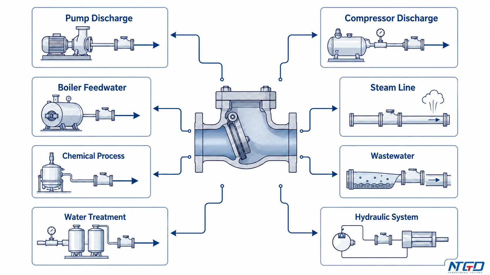
Where non-return valves are commonly used in industrial systems
Non-return valves are used where reverse flow can damage equipment, contaminate upstream media, disturb process control, or create unsafe operating conditions. Common industrial positions include pump discharge lines, compressor discharge lines, boiler feedwater systems, steam lines, chemical pipelines, wastewater systems, irrigation systems, water treatment plants, and utility piping.
They are especially important when fluid should move forward under normal pressure but must not return after the pump stops, the compressor cycles, pressure fluctuates, or downstream pressure becomes higher than upstream pressure. Correct selection can reduce the risk of backflow-related downtime, but the valve type, orientation, pressure condition, and media behavior must all be checked together.
How Does a Non-Return Valve Work?
A non-return valve works by using differential pressure. Forward flow creates enough pressure force to open the valve. Reverse flow or loss of forward pressure causes the valve to close.
The basic working sequence is:
- Upstream pressure rises.
- Forward pressure overcomes the valve’s cracking pressure.
- The disc, ball, flap, plate, diaphragm, or other closing element moves away from the seat.
- Flow passes through the valve in the allowed direction.
- Forward flow stops, or its pressure drops below the outlet-side pressure.
- Gravity, spring force, reverse pressure, or a combination of these forces pushes the closing element back toward the seat.
- Reverse flow is blocked.
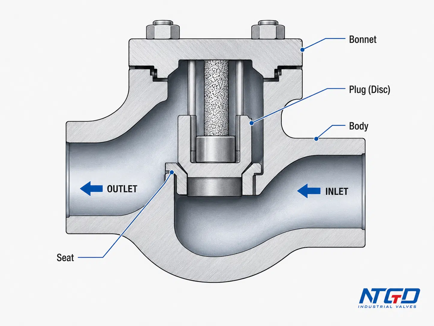
The exact movement depends on the valve type. A swing non-return valve uses a hinged disc. A lift non-return valve uses a guided disc or piston-like element. A ball non-return valve uses a ball. A spring-loaded design uses spring force to help close the valve quickly.
Forward flow opens the valve
During normal forward flow, the inlet side pressure is higher than the outlet side pressure. Once the pressure difference is high enough, the closing element lifts, swings, slides, or compresses away from the seat.
This minimum pressure difference is called cracking pressure. A valve with a very low cracking pressure may open more easily in low-pressure systems. A valve with a higher cracking pressure may be used where tighter closing control or specific service behavior is required. The correct value should be checked against the valve design, media condition, and project specification.
If the cracking pressure does not match the available system pressure, the valve may not open fully. That can create unstable flow, extra pressure drop, vibration, chattering, or accelerated wear.
Reverse flow closes the valve
When the downstream pressure becomes higher than the upstream pressure, the fluid attempts to move backward. In this condition, the closing element is pushed back toward the seat. Gravity, reverse-flow force, spring force, or a combination of these forces helps the valve close.
This is the main difference between a non-return valve and a manually operated isolation valve. A non-return valve responds automatically to flow and pressure conditions. It does not normally require an operator to close the valve when reverse flow begins.
Why differential pressure matters
Differential pressure controls both opening and closing behavior. If the upstream pressure is not high enough, the valve may not open fully. If the valve does not open fully, it can create extra pressure drop, vibration, unstable flow, or premature wear.
If reverse pressure occurs suddenly, the valve may close rapidly. In some systems, fast closure can contribute to valve slam or water hammer. This risk depends on valve type, flow velocity, pipe layout, pump behavior, and the closing mechanism.
For this reason, the non return valve working principle should always be reviewed together with the system’s available pressure, flow profile, and operating cycle. The valve does not operate in isolation; it responds to the actual pressure conditions created by the pipeline.
Cracking pressure, backpressure, and reseal pressure
These terms are important when reading a non-return valve datasheet or discussing selection with an engineering team.
| Term | Meaning | Why it matters |
|---|---|---|
| Cracking pressure | The minimum pressure difference needed to start opening the valve | If it is too high, the valve may not open properly in low-pressure service |
| Backpressure | Pressure acting from the outlet side toward the inlet side | Higher backpressure helps close the valve but can also affect system behavior |
| Reseal pressure | The pressure condition at which the valve closes tightly again | Important when reverse leakage must be minimized |
| Differential pressure | Pressure difference between upstream and downstream sides | Controls opening, closing, pressure drop, and stability |
For an external engineering-model reference, MathWorks describes cracking pressure as the initial resistance a check valve must overcome before it begins to open.
These terms should not be treated as fixed values for all non-return valves. They depend on valve design, size, spring force, seat design, installation orientation, and service condition.
In selection work, cracking pressure should be low enough for normal system flow to open the valve reliably, while reseal behavior should match the expected reverse-pressure condition. If reverse leakage is critical, the required shutoff expectation should be specified clearly rather than assumed from the valve name alone.
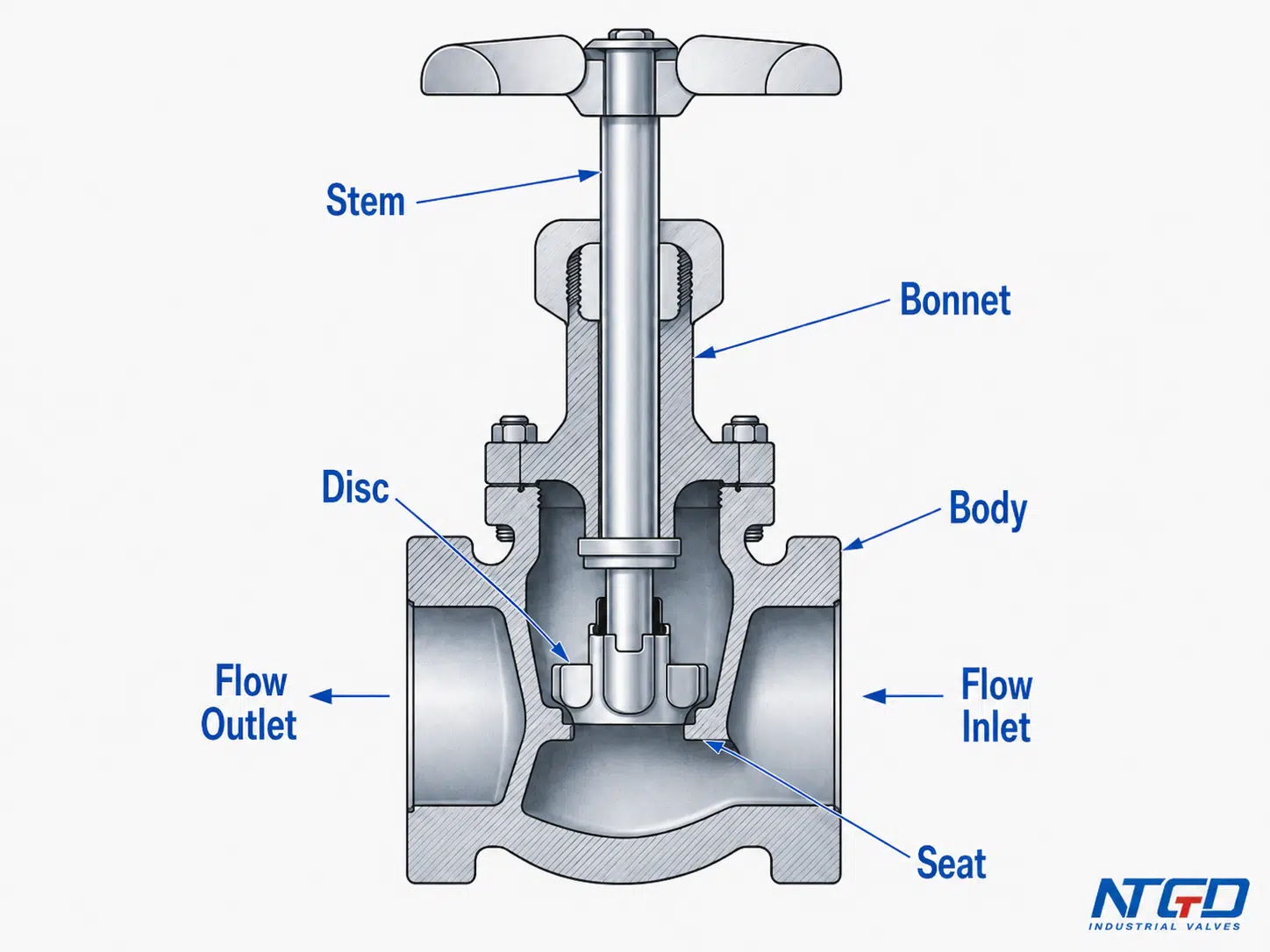
Non-Return Valve Diagram and Flow Direction
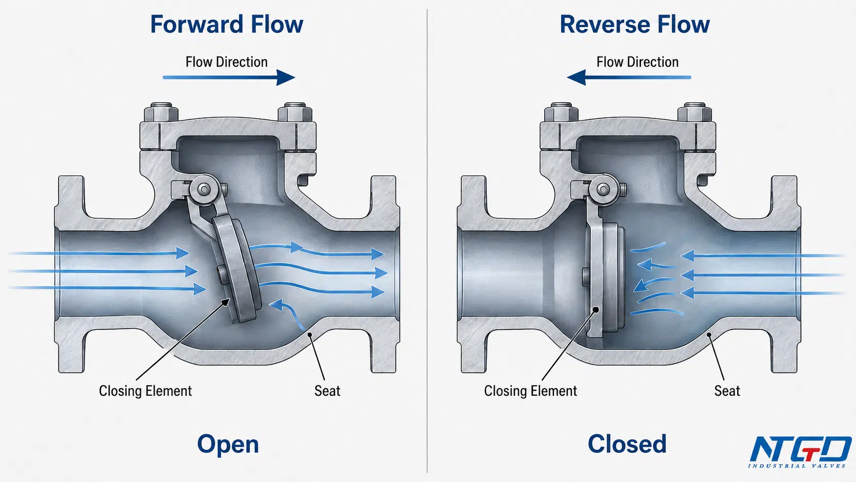
A non return valve diagram should show three basic things: the valve body, the allowed flow direction, and the internal closing element that blocks reverse flow.
A useful diagram does not need to show every manufacturing detail. For article-level understanding, the most important visual information is:
| Diagram element | What it shows | Why it matters |
|---|---|---|
| Flow arrow | The allowed direction of flow | Helps prevent reverse installation |
| Seat area | Where the closing element seals | Explains how reverse flow is blocked |
| Disc, ball, flap, or plate | The moving closure element | Shows the difference between valve types |
| Inlet and outlet | Pipeline direction | Helps connect the diagram with installation |
| Open / closed position | Working sequence | Helps explain how the valve responds to pressure |
What the flow arrow means
Most non-return valves have a flow direction mark on the body. The arrow shows the direction in which the valve is designed to open. If the valve is installed in the wrong direction, it may stay closed, restrict flow, or fail to prevent reverse flow correctly.
Correctly reading the flow arrow is the first installation check for reverse-flow protection. The arrow should match the intended pipeline flow from upstream to downstream. This should be verified during installation, commissioning, inspection, and troubleshooting.
How to read a simple non-return valve drawing
A basic non-return valve drawing normally shows forward flow entering the inlet, moving past the closing element, and exiting through the outlet. When reverse flow occurs, the closing element moves toward the seat and helps form a sealing barrier against flow from the outlet side back toward the inlet side.
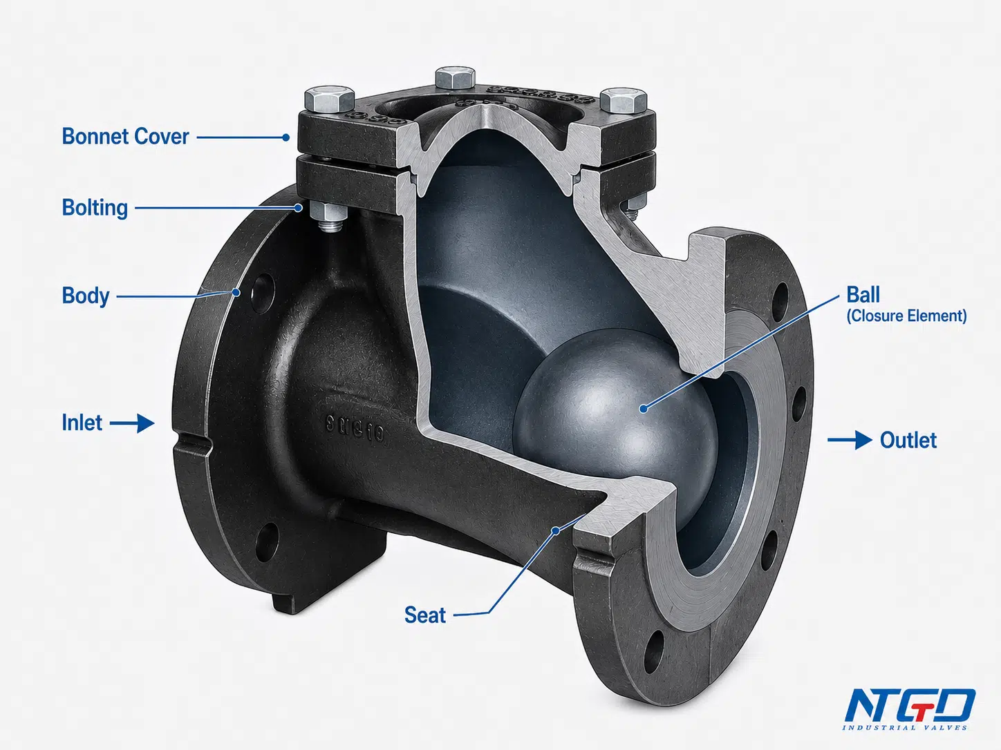
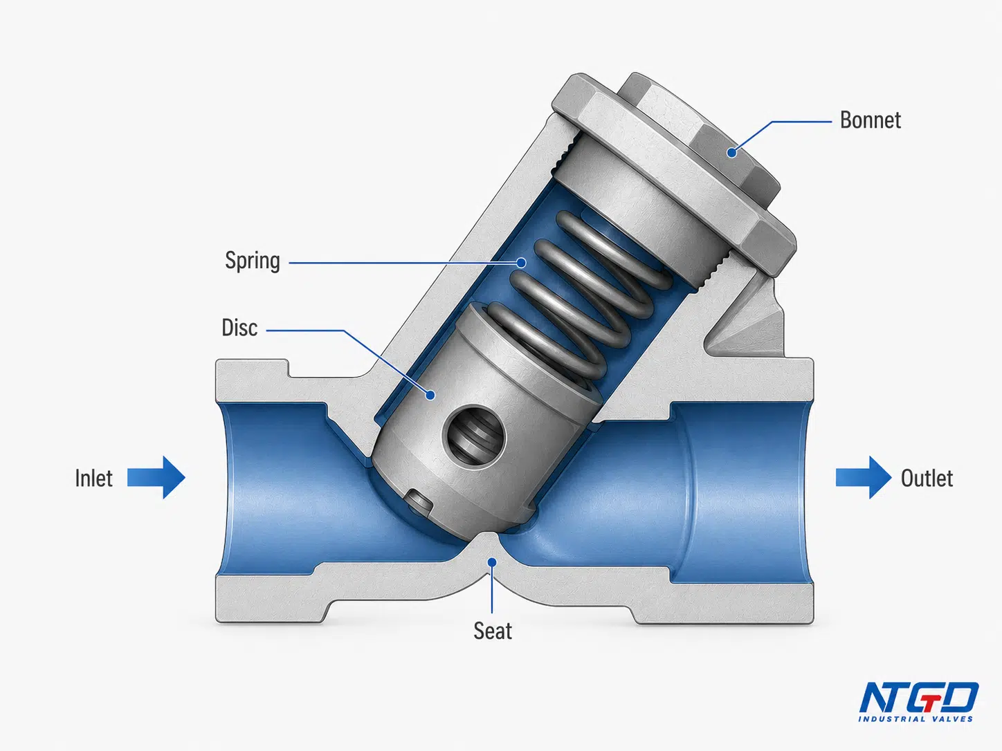
For a swing design, the drawing may show a disc rotating on a hinge. For a lift design, it may show a disc moving vertically or along a guide. For a ball design, it may show a ball moving away from or toward the seat. For a spring-loaded design, it may show a spring pushing the closure element toward the seat.
The drawing should be used to understand operation and flow direction, not to replace the manufacturer’s dimensional drawing, cross-section drawing, assembly drawing, or installation manual.
Diagram vs symbol: what this article covers and what it does not cover
This article explains practical non-return valve diagrams related to working principle, flow direction, and valve type. It does not act as a full P&ID symbol guide.
A P&ID symbol usually represents the valve’s function in a simplified schematic form. It does not show the actual internal mechanics, seat design, disc travel, spring arrangement, or installation limitations. For selection work, the physical design, closure mechanism, flow direction, installation orientation, and service conditions are more important than the symbol alone.
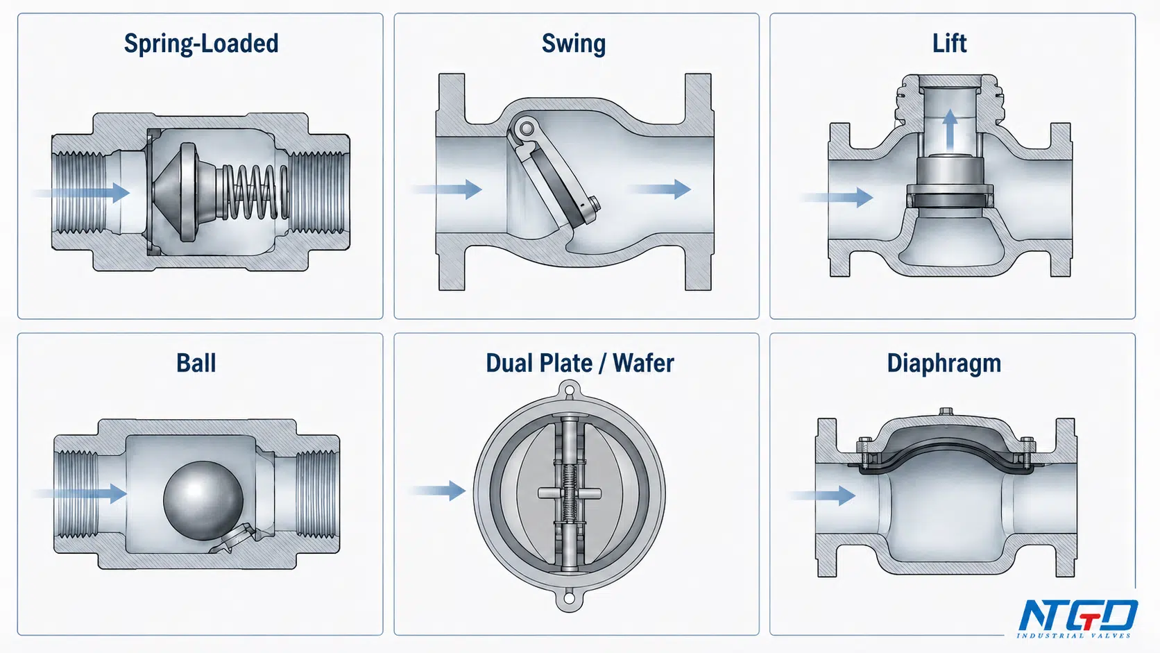
Main Types of Non-Return Valves
There are several types of non-return valves. They all prevent reverse flow, but they do not close in the same way. The internal closure element, travel distance, closing speed, pressure drop, and installation sensitivity can be very different.
Type overview table
| Type of non-return valve | Main closing element | Typical fit | Key selection caution |
|---|---|---|---|
| Spring-loaded in-line non-return valve | Disc or poppet with spring | Compact piping, faster closing, general liquid or gas service | Cracking pressure and spring force must match the system |
| Swing non-return valve | Hinged disc or flap | Large pipelines, relatively low flow resistance, steady forward flow | May slam if flow reverses quickly |
| Lift non-return valve | Guided disc or piston-like element | Higher-pressure service, controlled disc movement | Orientation and pressure drop must be checked |
| Ball non-return valve | Ball | Wastewater, viscous or slurry-like media, sediment-containing service where ball movement can tolerate some solids and operate quietly in suitable conditions | Ball movement and seat condition must remain reliable |
| Dual plate or wafer non-return valve | Two spring-assisted plates | Compact face-to-face installation, large pipelines | Spring, plate, and flow velocity must be reviewed |
| Diaphragm non-return valve | Flexible diaphragm | Low-pressure or special media applications | Material compatibility and pressure limits must be checked |
| Y-pattern non-return valve | Angled spring-loaded disc | Services requiring easier access for inspection | Larger body space may be required |
| Stop non-return valve | Disc plus manual closing mechanism | Boiler, power, or systems needing automatic and manual closing logic | Should not be treated as a standard simple check valve |
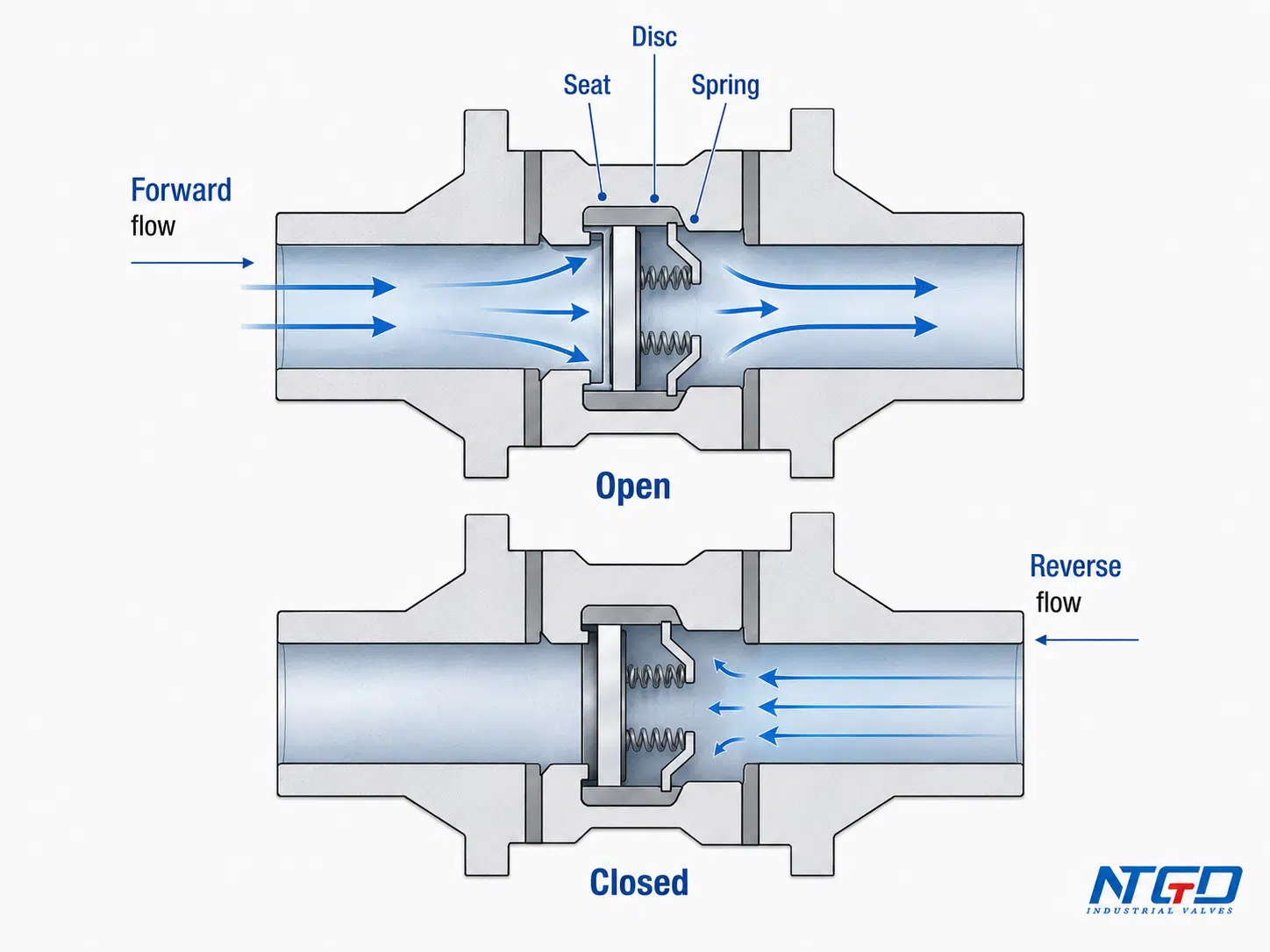
Spring-loaded in-line non-return valve
A spring-loaded in-line non-return valve uses spring force to help close the valve. During forward flow, upstream pressure pushes the disc or poppet away from the seat. When forward flow weakens or stops, the spring pushes the disc back toward the seat.
This design is compact and can close faster than some gravity-dependent designs. It is often useful where quick response is needed, but the spring force must be matched to the service. Too much spring force may increase cracking pressure and pressure loss. Too little spring force may reduce closing reliability or allow unstable movement in variable-flow service.
For a deeper review of spring force, cracking pressure, vertical or horizontal installation, and non-slam behavior, see NTGD’s spring-loaded check valve selection guide.
Swing non-return valve
A swing non-return valve uses a hinged disc that swings away from the seat during forward flow and returns to the seat when flow stops or reverses. It is widely used in larger pipelines and systems where a relatively open flow path is desired.
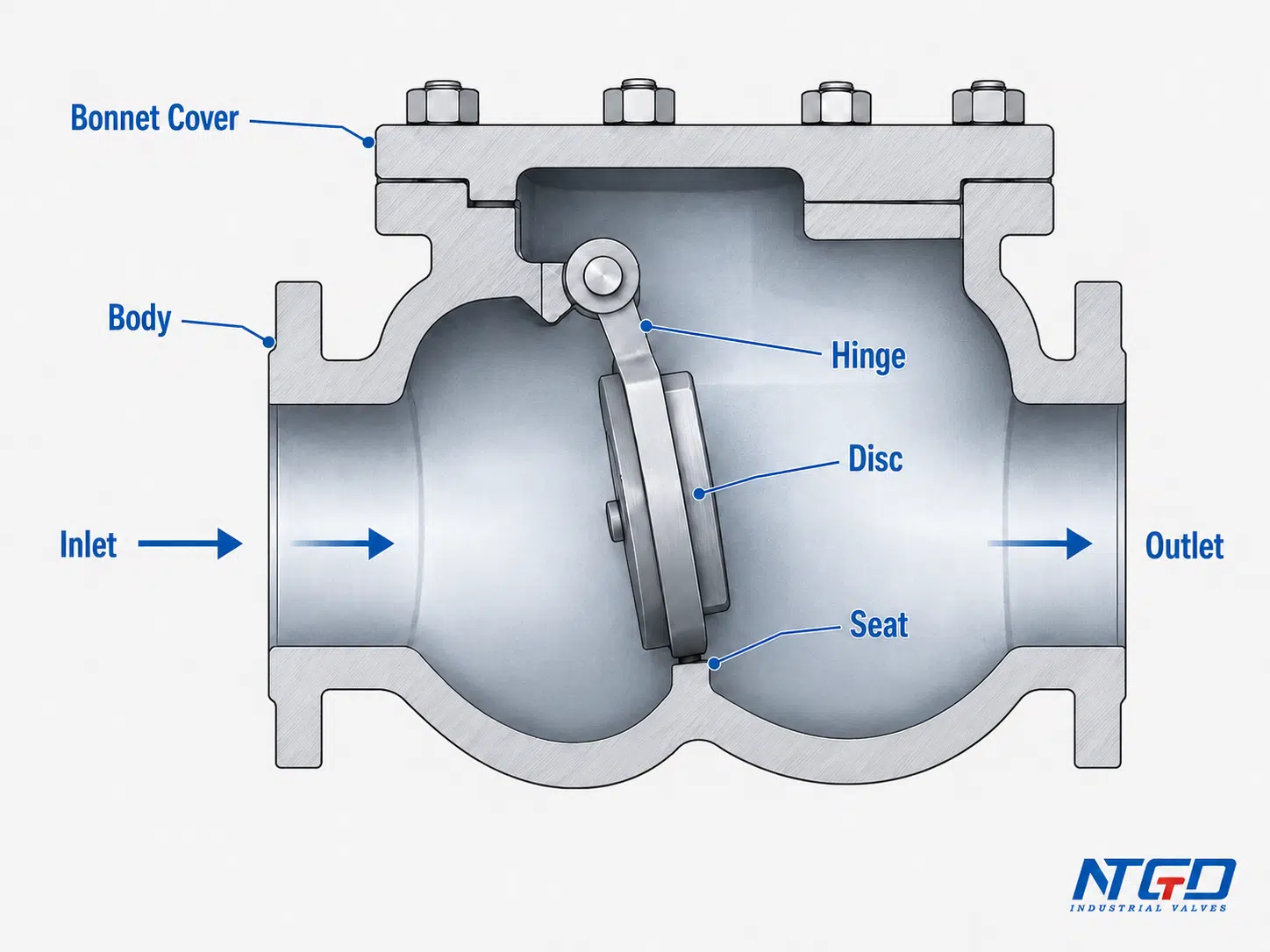
Swing designs can be suitable for water, wastewater, utility, and process lines, but the closing behavior must be reviewed. If reverse flow develops quickly, the disc may close with impact. This can increase the risk of valve slam, noise, vibration, or water hammer in some systems.
As a fit-check, swing non-return valves are often more suitable for steady forward-flow service than for systems with frequent pump starts, rapid flow reversal, or strong pressure fluctuation.
Where the design is described as a flap-style one-way valve, the non return flap valve page can help clarify flap movement, installation direction, and flap-versus-swing selection.
Lift non-return valve
A lift non-return valve uses a disc or piston-like closure element that lifts from the seat under forward pressure. When forward pressure drops, gravity, backpressure, or spring force returns the disc to the seat.
Lift non-return valves are often used where guided movement and tighter control of the disc are needed. They can be suitable for high-pressure or high-velocity service, depending on design. However, they may create more flow resistance than some swing designs because the flow path changes direction inside the valve.
A lift non-return valve can be installed in horizontal or vertical service only when the design supports that orientation. Gravity-assisted lift designs must be installed so the disc can return correctly to the seat. If orientation is wrong, the valve may not close reliably.
Ball non-return valve
A ball non-return valve uses a ball as the closing element. Forward flow moves the ball away from the seat. Reverse flow, gravity, or spring force moves the ball back to the seat to stop reverse flow.
Ball designs can be useful in wastewater, slurry-like, viscous, or sediment-containing service where the ball movement and seat design help tolerate certain suspended solids. They can also operate quietly in some services. However, the ball and seat must be compatible with the media, and the valve should be inspected if debris prevents full seating.
A ball non-return valve should be reviewed when solids, sediment, or viscous media are present, but it should not be assumed suitable for every dirty service without checking seat design, flow velocity, cleaning access, and installation orientation.
Dual plate or wafer non-return valve
A dual plate or wafer non-return valve uses two spring-assisted plates that open under forward flow and close when flow stops or reverses. The compact wafer-style body makes it common in space-limited installations and larger pipeline sizes.
Compared with a traditional swing design, a dual plate valve often has shorter disc travel and faster response. This can help reduce reverse-flow volume before closure, but spring behavior, plate movement, flow velocity, and water hammer risk still need to be checked for the actual system.
This type is often considered when installation space is limited or when large pipeline sizes require a compact face-to-face design. The final choice should still be checked against pressure drop, flow stability, and maintenance requirements.
For compact wafer-style construction and two-plate closure behavior, review the dual plate wafer check valve page before finalizing large-size or space-limited pipeline specifications.
Diaphragm non-return valve
A diaphragm non-return valve uses a flexible diaphragm to open under forward flow and seal against reverse flow. It can be used in selected low-pressure or special media applications where a flexible sealing element is suitable.
The main selection point is compatibility. Diaphragm material, temperature, pressure, chemical resistance, and expected cycle behavior must be checked before use. It should not be assumed that diaphragm-style non-return valves are suitable for all industrial pipelines.
Specialized types: Y-pattern and stop non-return valves
A Y-pattern non-return valve places the disc and spring arrangement at an angle to the main flow path. This can improve access for cleaning or inspection in some designs, but the body is usually larger and requires more installation space.
A stop non-return valve combines automatic non-return function with an external closing mechanism such as a handwheel, lever, or actuator. It can allow flow in normal service while also giving operators a way to close the valve manually.
This design is often associated with boiler, power, or critical process systems, but it should be selected according to the project specification rather than treated as a general-purpose non-return valve. If the manual shutoff function is not considered in the operating procedure, the valve may create unexpected flow restriction or incomplete system protection.
If the project requires both automatic reverse-flow prevention and a manual shutoff function, review the stop check valve page before treating it as a standard simple non-return valve.
Applications of Non-Return Valves in Industrial Systems
Non-return valves are used wherever backflow could damage equipment, contaminate media, reverse process flow, or create unsafe operating conditions. The correct application depends on both the system and the valve design.
Pumps and compressor discharge lines
One of the most common uses is on pump discharge lines. When a pump stops, downstream pressure can push fluid backward toward the pump. A non-return valve helps prevent reverse rotation, mechanical stress, and backflow into the suction side.
In compressor systems, a non-return valve can prevent compressed gas or air from flowing backward into the compressor after shutdown or pressure fluctuation.
For pump discharge systems where reverse flow, seat impact, or slam tendency is a concern, a tilting disc check valve may be reviewed as one possible anti-slam direction, depending on the actual flow and shutdown behavior.
Boiler, steam, and high-temperature service
Non-return valves can be used in boiler feedwater, steam, and high-temperature service, but the valve design must match the temperature, pressure, media, seat material, and applicable project requirements.
A boiler non-return valve may help prevent hot water or steam-related backflow from moving into upstream equipment. In high pressure steam service, selection should not be based only on valve type name. Material, pressure class, seat design, end connection, and installation conditions must be verified.
Chemical, wastewater, and process pipelines
In chemical and process systems, a non-return valve helps prevent unwanted mixing, contamination, reverse reaction flow, or process instability. Material compatibility becomes especially important in these services.
In wastewater systems, ball, swing, or specially designed non-return valves may be used depending on solids content, clogging risk, maintenance access, and flow conditions.
HVAC, water treatment, and utility systems
In utility water, cooling water, irrigation, and water treatment systems, non-return valves help maintain one-direction flow and reduce the risk of backflow between system sections. These services may appear simple, but orientation, flow velocity, debris, and pressure fluctuations still affect performance.
Application mapping table
| Application | Why a non-return valve is used | Common design consideration |
|---|---|---|
| Pump discharge | Prevents reverse flow toward the pump | Closing speed, water hammer risk, pressure drop. A valve that closes too slowly may allow more reverse flow, while harsh closure may increase pressure surge risk |
| Compressor discharge | Prevents backflow into compressor equipment | Gas compatibility, pressure rating, sealing behavior, and response during compressor cycling |
| Boiler feedwater | Helps prevent hot reverse flow into upstream equipment | Pressure, temperature, material, seat design, and project requirements |
| Steam line | Prevents reverse steam or condensate-related flow | Temperature rating, seat design, installation condition, and condensate behavior |
| Chemical process line | Prevents contamination or reverse process flow | Material compatibility, leakage tolerance, and cleaning or isolation strategy |
| Wastewater line | Prevents backflow in drainage or treatment systems | Solids handling, clogging risk, seat design, and maintenance access |
| Water treatment / utility line | Maintains one-direction flow | Orientation, flow velocity, debris control, and inspection access |
| Hydraulic system | Helps control reverse flow in selected circuits | Pressure, response speed, fluid compatibility, and circuit behavior |
Different applications require different priorities. A pump discharge line may focus on closing speed and water hammer control. A wastewater line may focus on solids handling and cleaning access. A chemical process line may focus on material compatibility and reverse contamination risk. Application mapping should therefore lead into selection review rather than replace it.
How to Select a Non-Return Valve for Industrial Service
A non-return valve should be selected by service condition, not only by nominal size. The same pipeline size can require different non-return valve designs depending on flow behavior, media, pressure, temperature, and installation layout.
For broader service-condition routing across valve types, NTGD’s industrial valve selection guide can be used before finalizing the non-return valve type, material, pressure class, and connection standard.
Wrong selection may lead to incomplete opening, unstable operation, reverse leakage, excessive pressure loss, difficult maintenance, or increased water hammer risk. These outcomes are not caused by the valve name alone; they usually result from a mismatch between valve design and actual service conditions.
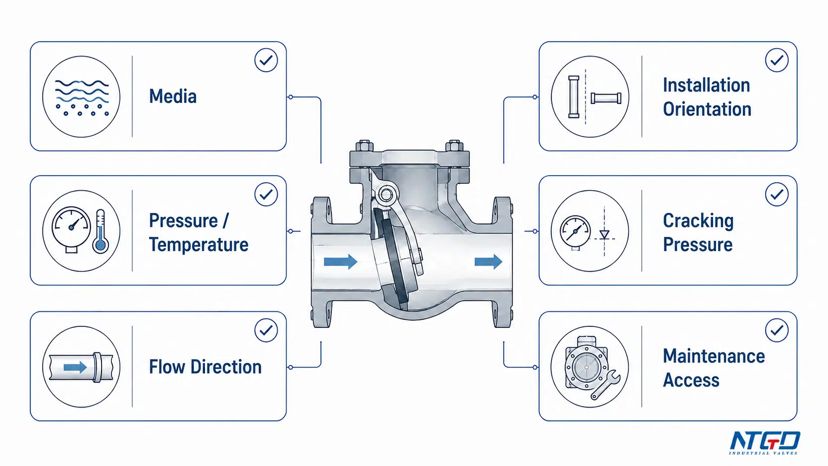
Media, pressure, and temperature
The first selection check is the media. Clean water, wastewater, steam, gas, viscous fluid, slurry-like media, and chemicals can require different body materials, seat materials, closure designs, and maintenance expectations.
Pressure and temperature must also be checked against the valve rating and project specification. For high-temperature or high-pressure service, the exact limit depends on material, pressure class, end connection, seat design, and manufacturer’s datasheet.
Flow direction and installation orientation
The valve must be installed in the correct flow direction. The body arrow should match the intended direction of flow. If installed backward, the valve may prevent normal forward flow or fail to protect the system.
Orientation is also important. Some non-return valves can be installed in horizontal or vertical pipelines. Others require a specific orientation because gravity helps the disc or ball return to the seat. This is especially important for lift non-return valves and certain swing or ball designs.
Cracking pressure and pressure drop
Cracking pressure affects whether the valve opens correctly under normal flow. If the available differential pressure is too low, the valve may remain partly closed, creating unstable flow or extra pressure loss.
Pressure drop also varies by design. A swing valve may offer a relatively open flow path in some services. A lift valve may create more flow resistance because the flow path changes direction. A spring-loaded design may add resistance from spring force. These effects should be checked against system requirements.
Solids, viscosity, and contamination risk
If the media contains solids, sediment, scale, fibers, or viscous fluid, the closure element and seat must be selected carefully. Debris can prevent full closure and cause reverse leakage. In these services, ball-type or specially designed wastewater non-return valves may be more suitable than a design with narrow internal passages.
Chemical contamination risk should also be considered. In food, beverage, chemical, and process service, reverse flow can mix media or contaminate upstream sections. Material compatibility and cleaning access become important selection factors.
Maintenance access and lifecycle considerations
A non-return valve is often installed in a position where it is expected to work automatically for long periods. However, automatic operation does not mean no maintenance. Seat wear, debris, corrosion, hinge wear, spring fatigue, or damaged sealing surfaces can affect performance.
Maintenance access should be reviewed before installation. A valve that is difficult to remove or inspect may create higher downtime cost later, even if it is inexpensive at the time of purchase. For services with dirty media, frequent cycling, or difficult shutdown conditions, maintenance access can be as important as the initial valve type.
Selection factor table
| Selection factor | Why it matters | What to confirm before selection |
|---|---|---|
| Media type | Affects material, seat, and closure design | Clean, dirty, viscous, corrosive, steam, gas, or liquid service |
| Pressure and temperature | Determines body and trim suitability | Pressure class, temperature range, material rating |
| Flow direction | Controls correct installation | Body arrow and pipeline flow direction |
| Installation orientation | Affects closure reliability | Horizontal, vertical upward, vertical downward, or special mounting |
| Cracking pressure | Affects opening behavior | Available differential pressure in normal flow |
| Pressure drop | Affects pump load and system efficiency | Valve type and flow path restriction |
| Water hammer risk | Affects pipe stress and valve damage | Flow velocity, pump stop behavior, closure speed |
| Solids or debris | Affects sealing and clogging | Seat design, cleaning access, strainer need |
| Maintenance access | Affects lifecycle cost | Access for inspection, cleaning, or replacement |
| End connection | Affects installation and sealing | Flanged, threaded, welded, wafer, or other project requirement |
A strong selection review should connect these factors together. For example, a valve with acceptable pressure class may still be unsuitable if it cannot close reliably in the installed orientation, or if the cracking pressure is too high for the available system pressure.
Advantages, Limitations, and Misuse Risks
Non-return valves provide important system protection, but they are not universal solutions. Their performance depends on correct selection, installation, and service conditions.
Engineering benefits when correctly selected
A correctly selected non-return valve can provide several benefits:
- Prevents reverse flow in pipelines.
- Protects pumps, compressors, boilers, and process equipment.
- Helps reduce contamination risk between process sections.
- Operates automatically without a normal external operator.
- Supports one-direction flow control in utility, process, and water systems.
- Can reduce equipment damage caused by backflow after shutdown.
- Can be used in horizontal or vertical installations when the design allows it.
These benefits depend on correct sizing, flow direction, orientation, material selection, and valve type.
Limitations that should be checked before use
Non-return valves also have limitations:
| Limitation | Why it matters |
|---|---|
| One-direction function only | It cannot replace an isolation valve where manual shutoff is required |
| Pressure drop | Lift, spring-loaded, or compact designs may add more resistance than a more open flow-path design, depending on construction |
| Orientation sensitivity | Gravity-assisted lift, swing, or ball designs may not close correctly if installed in the wrong position |
| Debris sensitivity | Foreign material can prevent full seating, especially where the seat or closure path is exposed to solids |
| Inspection difficulty | Some valves cannot be visually confirmed open or closed during operation |
| Pulsating service | Repeated pressure fluctuation can cause chattering, wear, or unstable operation |
| Reverse leakage | Sealing depends on seat design, condition, pressure, and media |
| Water hammer risk | Fast or delayed closure in certain systems can create pressure surge |
Water hammer, slamming, and reverse-flow risks
A non-return valve does not automatically eliminate water hammer. In some systems, incorrect valve selection can increase the risk of slam or pressure surge.
For example, a large swing disc may close after reverse flow has already started, causing impact at the seat. A spring-assisted or shorter-travel design may reduce reverse-flow volume before closure in suitable systems, but spring force and system dynamics must still be reviewed. A valve that is too large may operate partly open and become unstable.
A system-level check valve slam review is useful when pump shutdown, reverse velocity, valve travel distance, and closure speed may interact.
There is no single non-return valve type that eliminates water hammer in every system. Water hammer review should consider flow velocity, pump stop behavior, pipe length, valve location, closing speed, valve type, and operating procedure.
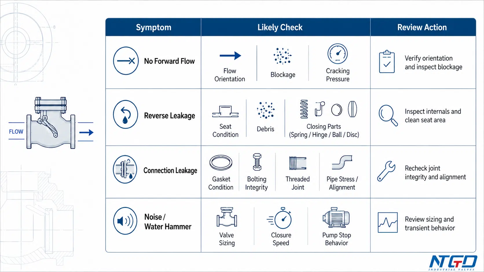
Troubleshooting and Maintenance Checklist
When a non-return valve does not operate correctly, the issue is often related to pressure condition, incorrect installation, debris, damaged seat, worn closure element, or unsuitable valve selection.
Before inspection or repair, the line should be isolated, depressurized, drained if required, and handled according to site safety procedures and manufacturer instructions.
No forward flow
If the non-return valve does not allow forward flow, possible causes include insufficient upstream pressure, wrong installation direction, blocked pipeline, jammed closure element, or cracking pressure that is too high for the system.
Reverse flow is not stopped
If reverse flow continues through the valve, the seat may be blocked by debris, the disc or ball may be damaged, the hinge or guide may be worn, the spring may be damaged, or the valve may be installed in the wrong orientation.
Leakage at connection
Connection leakage is usually related to flange gasket condition, threaded joint sealing, loose bolting, incorrect torque, damaged sealing surfaces, or pipe stress. The correction should follow the valve and piping specification.
Leakage through body or seat
Leakage through the valve body, cover, or seat area can indicate body damage, corrosion, erosion, worn seat surfaces, damaged closure element, or foreign material trapped at the sealing surface.
Troubleshooting matrix
| Symptom | Likely cause | Inspection point | Typical action |
|---|---|---|---|
| No forward flow | Upstream pressure too low | Compare system pressure with cracking pressure | Verify pressure condition and valve selection |
| No forward flow | Valve installed backward | Check body flow arrow | Reinstall in correct flow direction if needed |
| No forward flow | Pipeline or valve blocked | Inspect inlet, seat area, and internal passage | Remove debris after safe shutdown |
| Reverse flow not stopped | Debris on seat | Inspect sealing area | Clean valve and check upstream filtration |
| Reverse flow not stopped | Damaged disc, ball, plate, spring, or hinge | Inspect closure element | Repair or replace damaged components |
| Reverse flow not stopped | Wrong orientation | Check installation direction and mounting position | Correct installation according to design |
| Connection leakage | Loose bolts or damaged gasket | Inspect flange or threaded connection | Tighten or replace sealing component as specified |
| Body leakage | Cracked, corroded, or eroded body | Inspect body and cover area | Remove from service and replace or repair according to specification |
| Noise or vibration | Valve chattering or unstable flow | Check flow velocity and valve sizing | Review valve size, type, and operating condition |
| Water hammer after pump stop | Closure speed mismatch | Review pump stop behavior and valve type | Consider alternative closure design or surge control review |
If debris repeatedly prevents full seating, the system should also be reviewed for upstream filtration, such as an industrial Y strainer or another suitable strainer arrangement.
Preventive checks
For services where shutdown is costly or media conditions are severe, preventive checks can help reduce unexpected failure. Common checks include inspecting seat condition, confirming that debris is not trapped in the valve, verifying spring or hinge movement where applicable, and reviewing valve behavior after abnormal noise, vibration, or water hammer events.
If repeated reverse leakage, severe vibration, body leakage, or suspected water hammer occurs, the system should be safely isolated and reviewed by qualified personnel before returning to normal service.
Frequently Asked Questions
In industrial selection, is a non-return valve the same as a check valve?
In many industrial contexts, a non-return valve and a check valve refer to the same general valve function: allowing flow in one direction and preventing reverse flow. This article uses non-return valve as the main term. For users who need to browse the broader product family, NTGD’s check valve product range covers related check valve types and product options.
Is a non-return valve the same as an NRV valve?
Yes. NRV is commonly used as an abbreviation for non-return valve. However, this article does not focus on NRV full form, NRV parts, or detailed NRV component naming. It focuses on the working principle, types, diagram, applications, and industrial selection of non-return valves.
Can a non-return valve be installed vertically or horizontally?
Some non-return valves can be installed vertically or horizontally, but this depends on the valve design. Spring-loaded designs are often less dependent on gravity. Lift, swing, and ball designs may have orientation limits. The valve’s flow arrow, datasheet, and manufacturer instructions should always be checked before installation.
What does the arrow mean in a non-return valve diagram?
The arrow shows the allowed flow direction. The valve is designed to open in the direction of the arrow and close against reverse flow. If the valve is installed opposite to the arrow direction, it may block normal flow or fail to protect the system.
What is cracking pressure in a non-return valve?
Cracking pressure is the minimum differential pressure needed to start opening the valve. If the upstream pressure cannot overcome the cracking pressure, the valve may stay closed or open only partially. This value is important in low-pressure systems and systems with variable flow.
Which type of non-return valve is used for pumps?
Pump discharge lines often use swing, spring-loaded, dual plate, or other application-specific non-return valves. The best choice depends on flow rate, pump stop behavior, water hammer risk, pressure drop, pipe size, and maintenance access.
Can a non-return valve be used in boiler or steam service?
Yes, selected non-return valves can be used in boiler, feedwater, steam, or high-temperature service. However, these services require careful review of pressure rating, temperature rating, material, seat design, end connection, and project requirements.
Does a non-return valve prevent all leakage?
Not necessarily. A non-return valve is designed to prevent reverse flow, but reverse leakage depends on seat design, pressure condition, media cleanliness, wear, debris, and valve condition. If tight shutoff is critical, the required leakage performance should be specified clearly.
What is the difference between a non-return valve diagram and a P&ID symbol?
A non-return valve diagram usually helps explain the physical valve, internal closure movement, flow direction, and working principle. A P&ID symbol is a simplified schematic symbol used in piping documentation. It shows valve function in a system drawing, but it does not explain the actual internal mechanism or selection details.
Conclusion
A non return valve is an automatic one-way valve used to prevent reverse flow in industrial pipelines. Its working principle is based on differential pressure: forward pressure opens the valve, while reverse pressure or loss of forward flow closes it.
The main selection challenge is that different non-return valves behave differently. A swing design, lift design, ball design, spring-loaded design, dual plate design, diaphragm design, Y-pattern design, and stop non-return valve can all prevent backflow, but their flow resistance, closing speed, installation sensitivity, maintenance access, and service suitability are not the same.
For industrial service, the correct choice should consider media, pressure, temperature, cracking pressure, flow direction, installation orientation, solids content, water hammer risk, and lifecycle maintenance. A simple non-return valve diagram can help explain flow direction and working logic, but final selection should always be checked against the project specification and the manufacturer’s datasheet.
If you are confirming a non-return valve specification, the checkpoints above provide a practical starting framework for reviewing the valve type against actual service conditions.
For industrial non-return valve selection, confirm the media, pressure, temperature, flow direction, installation orientation, end connection, and expected operating behavior before finalizing the specification. NTGD Valve can support application review and RFQ-ready technical clarification for non-return valves used in pump, boiler, steam, water, wastewater, chemical, and general process systems.
For product-specific size range, pressure rating, material, end connection, and application data, review NTGD’s non return check valve product specifications before sending final RFQ details.
