Author Name: Bruce Zheng
Author Role: Co-Founder and Valve Engineer at NTGD Valve
Author Bio: Bruce Zheng is Co-Founder and Valve Engineer at NTGD Valve, focusing on industrial valve selection, application, and technical content for global B2B buyers.
Last Updated: June 4, 2026
A gear operated butterfly valve is a butterfly valve fitted with a manual gearbox or gear operator. Instead of turning the valve stem directly with a lever, the operator turns a handwheel. The handwheel drives a gearbox, usually a worm gear mechanism, which rotates the stem and disc in a controlled 90-degree movement.
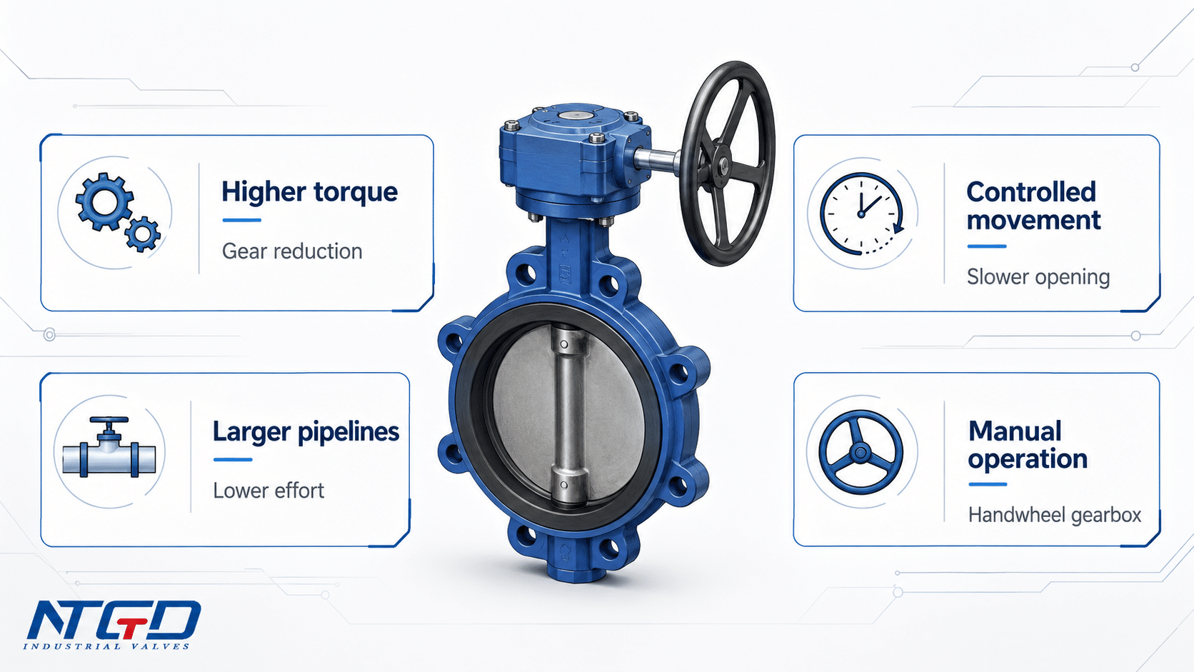
In simple terms, it is a manual butterfly valve with a built-in torque multiplier. The gear operator converts handwheel input into slower, higher-torque stem output, making the valve easier and safer to operate when direct lever operation becomes difficult.
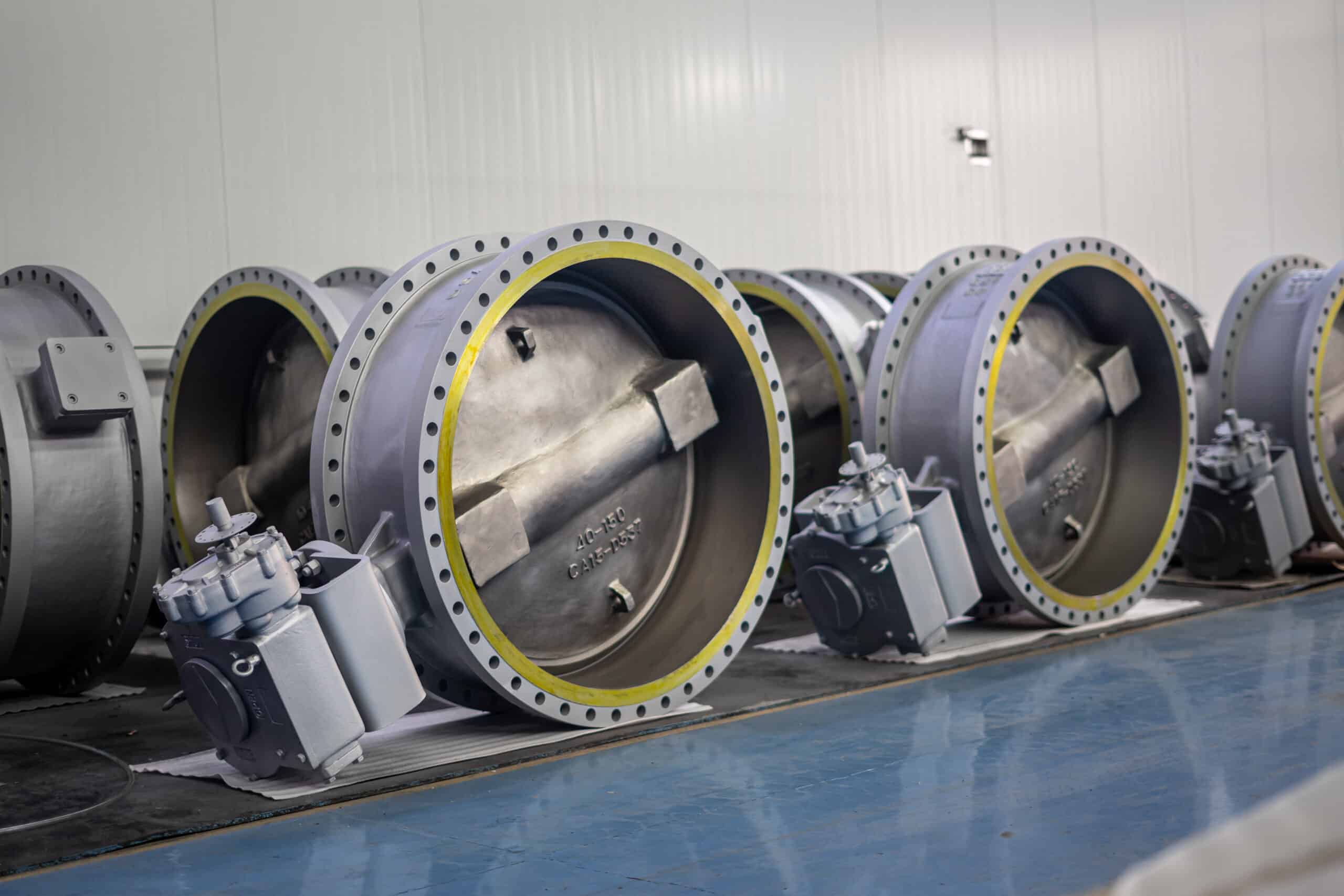
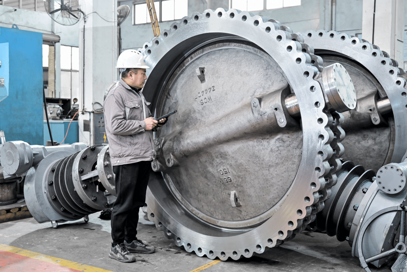
Gear operated butterfly valves are commonly used on medium to large pipelines, higher-torque services, or installations where gradual manual operation is preferred. The gearbox reduces manual effort, gives the operator better control over opening and closing speed, and helps hold the disc position more securely.
A gear operated butterfly valve is not a different valve body type. It is a butterfly valve with a specific operation method. The valve may still be wafer, lug, flanged, double flanged, or eccentric in body design. The “gear operated” part refers to how the valve is opened and closed.
What Is a Gear Operated Butterfly Valve?
A gear operated butterfly valve is a quarter-turn valve that uses a handwheel and gearbox to control the disc. The disc is mounted on a stem inside the valve body. When the gearbox turns the stem, the disc rotates between open, partially open, and closed positions.
In a simple manual butterfly valve with lever operation, the handle directly turns the stem. In a gear operated design, the handwheel input first passes through a gearbox. This gear reduction increases output torque and makes the valve easier to operate, especially on larger sizes or higher-torque services.
Quick Answer
A gear operated butterfly valve is a butterfly valve equipped with a manual gear operator. The gear operator acts as a torque multiplier, converting handwheel rotation into controlled stem and disc movement. The valve disc still rotates 90 degrees, but the handwheel may need multiple turns because the gearbox reduces speed and increases torque.
Gear Operation Is an Operating Method, Not a Body Type
Terms such as wafer butterfly valve, lug butterfly valve, and flanged butterfly valve describe how the valve body connects to the pipeline. Terms such as lever operated, gear operated, pneumatic actuated, and electric actuated describe how the valve is operated.
A gear operated butterfly valve can therefore be:
- a gear operated wafer butterfly valve;
- a gear operated lug butterfly valve;
- a gear operated flanged butterfly valve;
- a double flanged gear operated butterfly valve;
- an eccentric or double eccentric gear operated butterfly valve.
The gearbox does not change the basic butterfly valve principle. It changes how torque is applied to the stem and disc.
Gearbox Operated, Geared, and Gear Operated Butterfly Valves
In industrial use, buyers may use several similar terms:
| Term | Practical Meaning |
|---|---|
| Gear operated butterfly valve | Most common technical term for a butterfly valve operated by gearbox and handwheel |
| Gearbox operated butterfly valve | Same general meaning, emphasizing the gearbox |
| Geared butterfly valve | Shorter wording, often used in product discussions |
| Butterfly valve with gear operator | Buyer-oriented wording, usually referring to a butterfly valve supplied with a mounted gearbox |
| Butterfly valve gearbox | Usually refers to the gearbox component integrated with the valve operator, not the complete valve body |
For this article, the main subject is the complete gear operated butterfly valve, not a spare gearbox, replacement gearbox, or gearbox parts catalog.
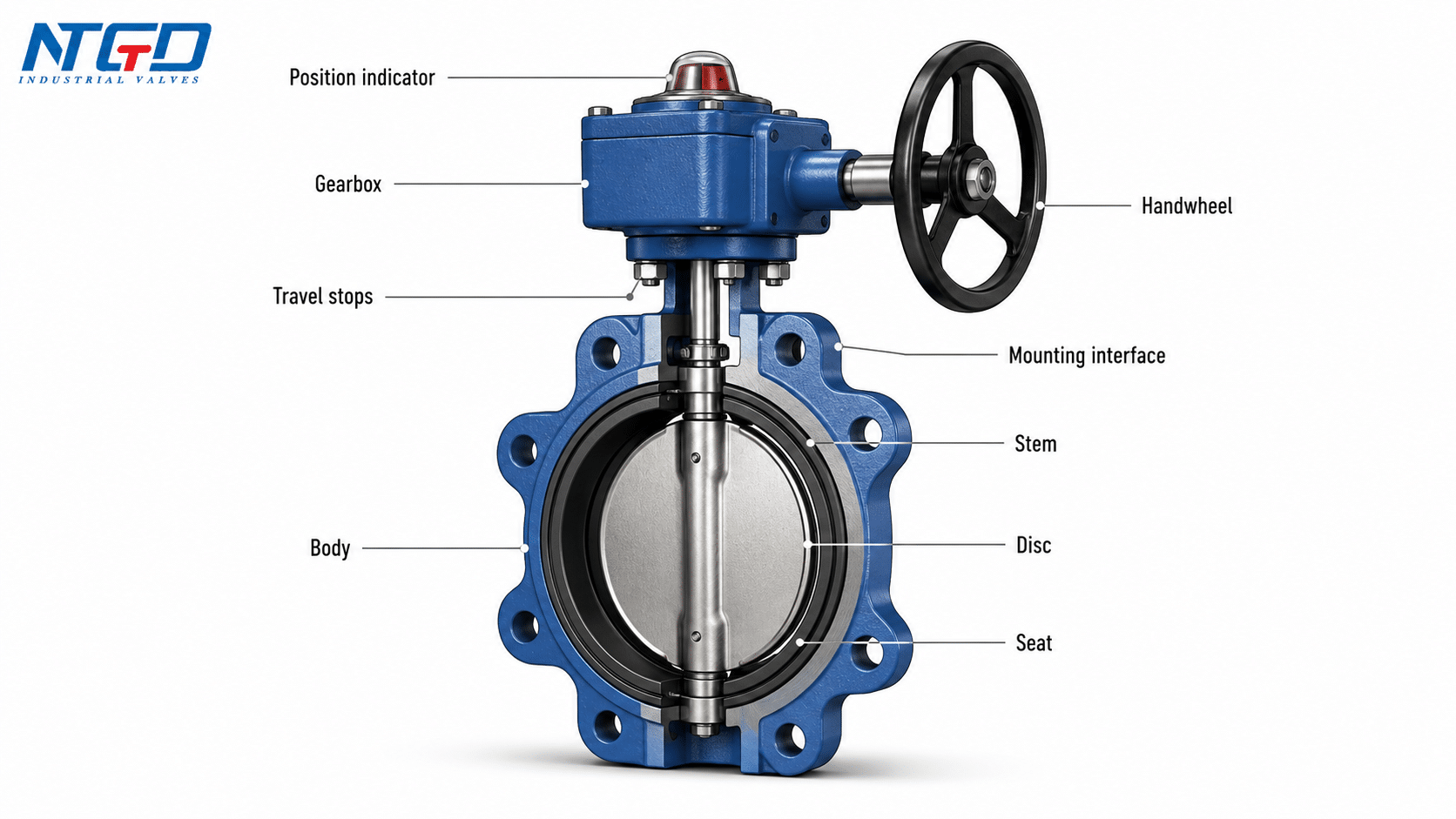
In practical terminology, the gear operator usually refers to the complete manual operating unit, including the gearbox, handwheel, mounting interface, position indicator, and travel stops. The gearbox is the torque-multiplying reduction mechanism inside that operator assembly.
How a Gearbox Operated Butterfly Valve Works
The working principle can be summarized as:
handwheel → worm gear / gearbox → output shaft / stem → disc rotation → open, closed, or intermediate position
When the operator turns the handwheel, the gearbox reduces the input speed and increases the output torque. The gearbox then transfers this torque to the valve stem. The stem rotates the disc inside the valve body.
This conversion is the key value of a gearbox operated butterfly valve. It changes a relatively low handwheel input into slower, higher-torque stem output, allowing the operator to control larger or higher-torque valves with less physical effort.
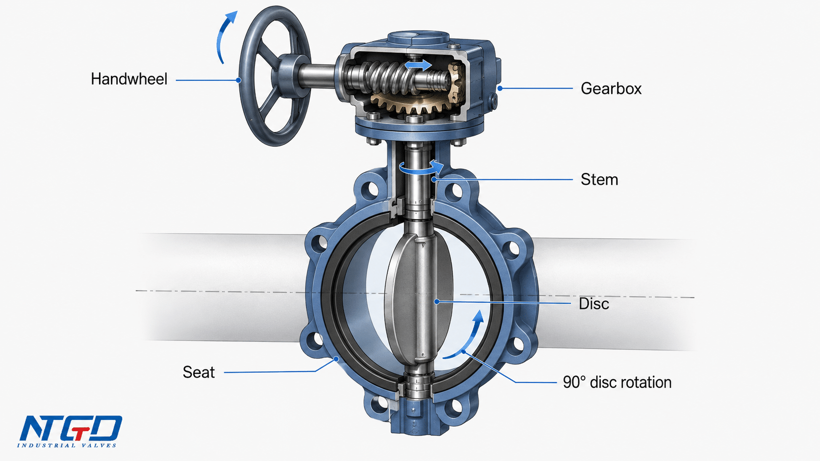
Handwheel Input, Worm Gear Reduction, and Stem Rotation
Most manual gear operated butterfly valves use a worm gear or similar reduction mechanism. The worm gear allows a relatively small handwheel effort to generate higher output torque at the stem.
This is useful because butterfly valve torque is affected by several conditions:
- valve size;
- seat design;
- pressure differential;
- disc position;
- media condition;
- operating frequency;
- installation and aging condition.
As torque increases, direct lever operation can become difficult or unsafe. A butterfly valve gear operator makes the movement more gradual and easier to control.
Why the Disc Is Quarter-Turn but the Handwheel May Turn Multiple Times
A butterfly valve is still a quarter-turn valve because the disc moves about 90 degrees from fully closed to fully open.
However, the handwheel on a gear operated butterfly valve usually does not turn only 90 degrees. Because of gear reduction, the handwheel may rotate several turns while the disc only rotates 90 degrees. This is normal.
The result is:
- slower operation;
- lower handwheel effort;
- better control of disc movement;
- reduced chance of sudden closure;
- easier operation on larger or higher-torque valves.
This multi-turn handwheel behavior gives the operator more control over opening and closing speed. That can be valuable in larger sizes, higher-torque services, or systems where sudden disc movement may create pressure surge or water hammer risk.
This point matters because some users compare a gear operated valve with a handwheel-operated valve. In many gear operated butterfly valves, the handwheel is part of the gear operator. The real comparison is usually between direct lever operation and geared handwheel operation.
Position Indicator, Travel Stops, and Self-Locking Gear Function
A butterfly valve gearbox may include several useful features:
| Gearbox Feature | Function | Why It Matters |
|---|---|---|
| Position indicator | Shows whether the valve is open, closed, or partially open | Helps operators confirm valve position visually |
| Travel stops | Limit the open and closed positions | Helps prevent over-travel or misalignment |
| Self-locking worm gear | Helps hold the disc position under normal operating conditions | Useful for intermediate positions and safer manual control |
| Mounting interface | Connects the gearbox to the valve top works | Must match valve stem and mounting pattern |
| Handwheel | Provides manual input | Must be accessible for operation and maintenance |
A worm gear operator can help hold the disc position when the handwheel stops moving. However, actual holding behavior still depends on gearbox design, torque load, valve condition, installation, and manufacturer specification. It should not be assumed without checking the valve and gearbox design.
When Should a Butterfly Valve Use Gear Operation?
Gear operation is selected when direct lever operation becomes impractical, uncomfortable, or risky. There is no universal valve size at which all butterfly valves must use a gearbox. The decision depends on operating torque, pressure, seat design, frequency of operation, and site conditions.
Valve Size, Operating Torque, and Pressure Differential
As butterfly valves become larger, the torque required to move the disc normally increases. Higher pressure differential and tighter seat designs can also increase operating torque.
Gear operation is commonly considered when:
- the valve is medium to large size;
- the lever force would be too high for comfortable operation;
- the valve is operated under higher differential pressure;
- the disc must move gradually instead of snapping open or closed;
- the valve is installed in a location where direct lever movement is difficult.
The actual threshold should be judged by the manufacturer’s torque data, seat design, pressure differential, media condition, and project specification—not by a fixed DN or inch size alone.
Controlled Opening and Closing vs Fast Manual Operation
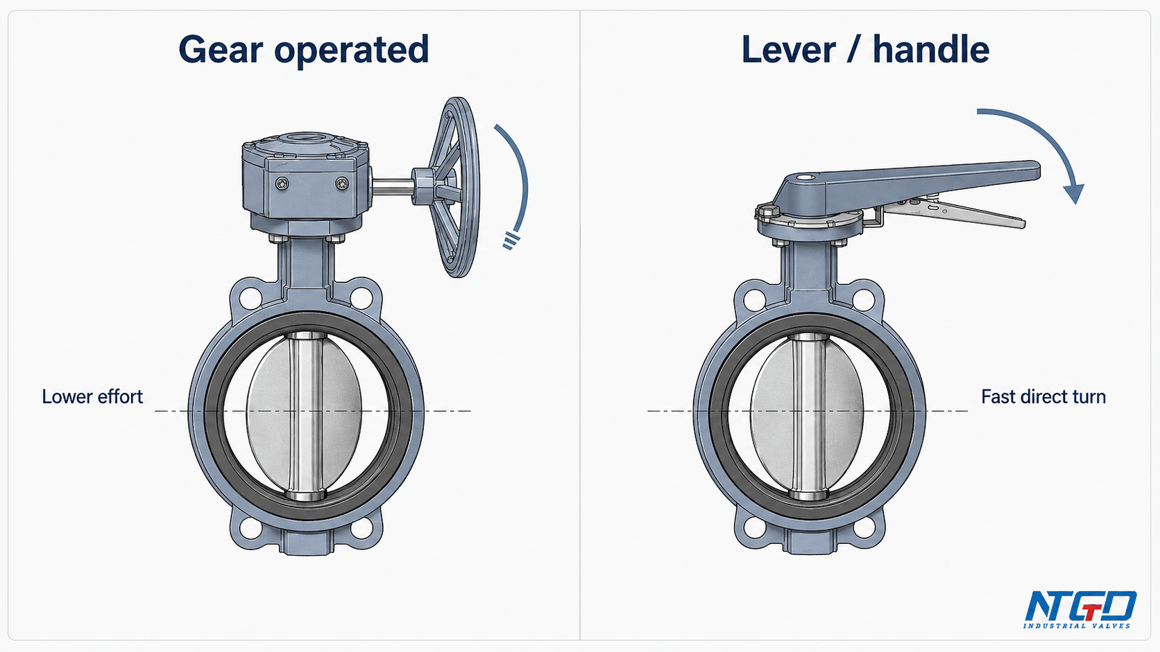
A lever-operated butterfly valve opens and closes quickly. This can be useful for small valves and simple isolation service.
A gear operated butterfly valve moves more slowly because the handwheel turns through a gearbox. This slower movement can be an advantage when the process requires more controlled operation.
| Operation Need | Gear Operation Fit |
|---|---|
| Fast open / close on small low-torque valves | Usually less necessary |
| Smooth manual control on larger valves | Strong fit |
| Reduced manual force | Strong fit |
| Gradual operation to avoid sudden flow change | Strong fit |
| Frequent emergency shutoff | May not be ideal because operation is slower |
| Precise control valve duty | Must be reviewed carefully; a butterfly valve is not automatically a precision control valve |
Operator Safety, Water Hammer Risk, and Site Access
Gear operation can reduce operator effort and help avoid sudden disc movement. In some piping systems, rapid valve closure can increase transient pressure risk. A geared handwheel gives the operator more gradual control than a direct lever.
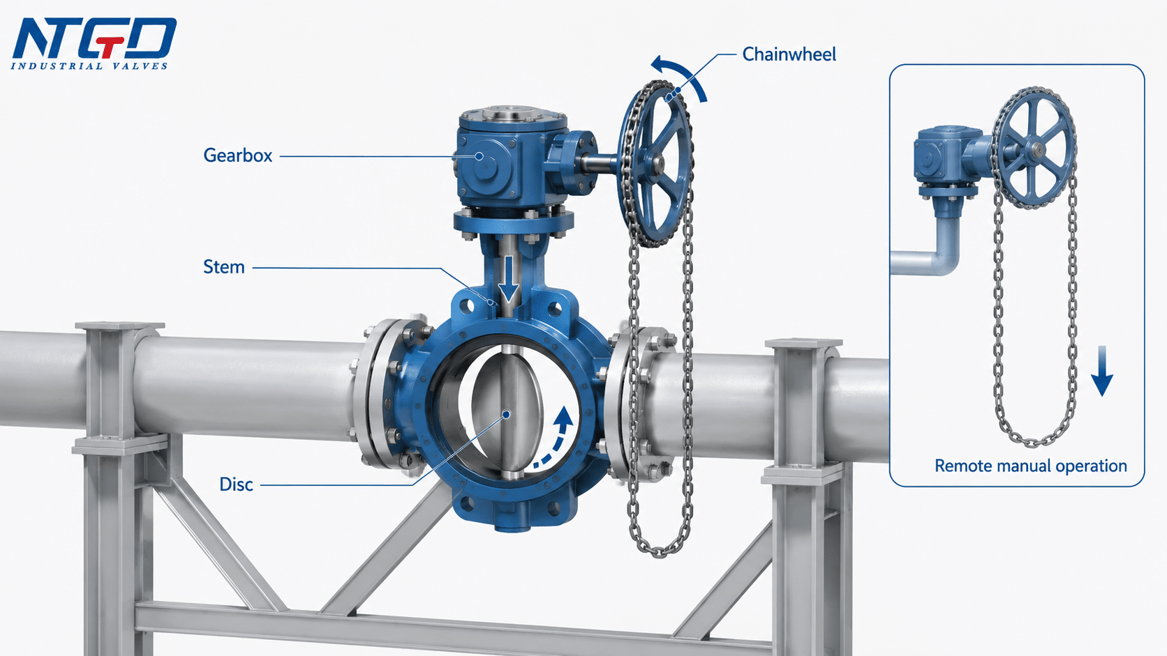
Site access also matters. If a valve is installed overhead, underground, near a wall, or in a confined area, the operator arrangement may need a chainwheel, extension stem, lock, or special handwheel access arrangement. These details should be reviewed before ordering.
The practical selection question is not “what size is the valve?” but “does the actual operating torque, site access, and process risk make direct lever operation uncomfortable, unsafe, or unsuitable?”
Main Components of a Gear Operated Butterfly Valve
A gear operated butterfly valve combines the normal pressure-containing and sealing components of a butterfly valve with a manual gear operator.
The table below shows how each component affects operation, selection, and maintenance. It is not a spare-parts catalog; it is a functional overview for valve selection and field review.
| Component | Function | Selection / Maintenance Impact |
|---|---|---|
| Valve body | Holds the internal components and connects to the pipeline | Body type affects connection style, face-to-face design, pressure class, and installation method |
| Disc | Rotates inside the flow path to open, throttle, or close the valve | Disc material and profile affect torque, flow resistance, and corrosion resistance |
| Stem / shaft | Transfers gearbox torque to the disc | Stem design affects torque transmission and alignment |
| Seat / liner | Provides the sealing surface between disc and body | Seat material affects shutoff performance, temperature range, chemical compatibility, and torque |
| Gasket / flange sealing area | Seals between valve body and pipeline flanges where applicable | Gasket selection depends on flange type, media, pressure, and installation method |
| Handwheel | Provides manual input to the gearbox | Must be accessible and suitable for the required operating effort |
| Gearbox / gear operator | Reduces speed and increases output torque to rotate the stem | Must match valve torque, stem size, mounting interface, environment, and operating frequency |
| Worm gear / gear segment | Creates mechanical advantage inside the gearbox | Worn or damaged gears may cause backlash, hard operation, or loss of movement |
| Position indicator | Shows disc position | Misalignment can cause incorrect open / closed reading |
| Travel stops | Limit open and closed positions | Incorrect adjustment may prevent full opening or full closure |
| Mounting interface | Connects gearbox to the valve top works | Must match the valve stem and mounting pattern; not every gearbox is interchangeable |
A butterfly valve gearbox should be selected with the valve, not treated as a generic spare part. Compatibility depends on stem dimensions, required torque, mounting interface, gearbox rating, and service environment.
For selection, the gearbox or gear operator must match the valve top works, stem size, mounting interface, and torque requirement. A mismatch may cause difficult operation, inaccurate position indication, stem damage, or premature gearbox wear.
Gear Operated vs Lever / Handle Operated Butterfly Valves
The most common comparison is not really “gear operated valve vs handwheel.” A gear operated butterfly valve often uses a handwheel. The more accurate comparison is:
gear operated butterfly valve vs lever / handle operated butterfly valve
A lever-operated butterfly valve uses a handle to turn the stem directly. A gear operated butterfly valve uses a handwheel connected to a gearbox, and the gearbox turns the stem.
The Main Difference in Operation
| Factor | Gear Operated Butterfly Valve | Lever / Handle Operated Butterfly Valve |
|---|---|---|
| Operating method | Handwheel drives gearbox, gearbox turns stem | Lever directly turns stem |
| Disc movement | Disc still rotates 90 degrees | Disc rotates 90 degrees |
| Hand movement | Handwheel may require multiple turns | Lever usually moves through a quarter turn |
| Operating torque | Lower manual effort for higher torque valves | Higher manual effort as valve size or torque increases |
| Operating speed | Slower but more controlled | Faster but less gradual |
| Suitable valve size | Common for medium and larger valves or higher-torque service | Common for smaller valves and simpler service |
| Control feel | Better gradual movement | More direct, faster movement |
| Space requirement | Handwheel may need less sweep space than a lever | Lever requires swing space |
| Cost | Typically higher because a gearbox is added | Typically lower, depending on size and valve design |
| Maintenance | Gearbox condition should be inspected according to service severity | Simpler mechanism, but maintenance still depends on service conditions |
| Typical use | Larger pipelines, utilities, water treatment, HVAC, industrial systems | Small lines, low torque service, quick manual operation |
Operation method should be selected by actual torque requirement, not valve size alone. A smaller valve with higher pressure differential, a tight seat, or difficult media may require more operating torque than a larger low-pressure valve.
When Lever Operation May Still Be Enough
Lever operation can be suitable when:
- the valve is small;
- torque is low;
- quick manual operation is needed;
- the valve is easy to access;
- cost and simplicity are more important than torque reduction.
Gear operation is not the best choice for every service. It becomes valuable when the process actually needs torque advantage, controlled movement, safer operation, or better position management.
Gear Types, Operator Options, and Connection Configurations
In practice, the term butterfly valve gear type can be confusing because it may refer to the valve’s operating mechanism or to the body / connection configuration. These two classifications should be separated before selection.
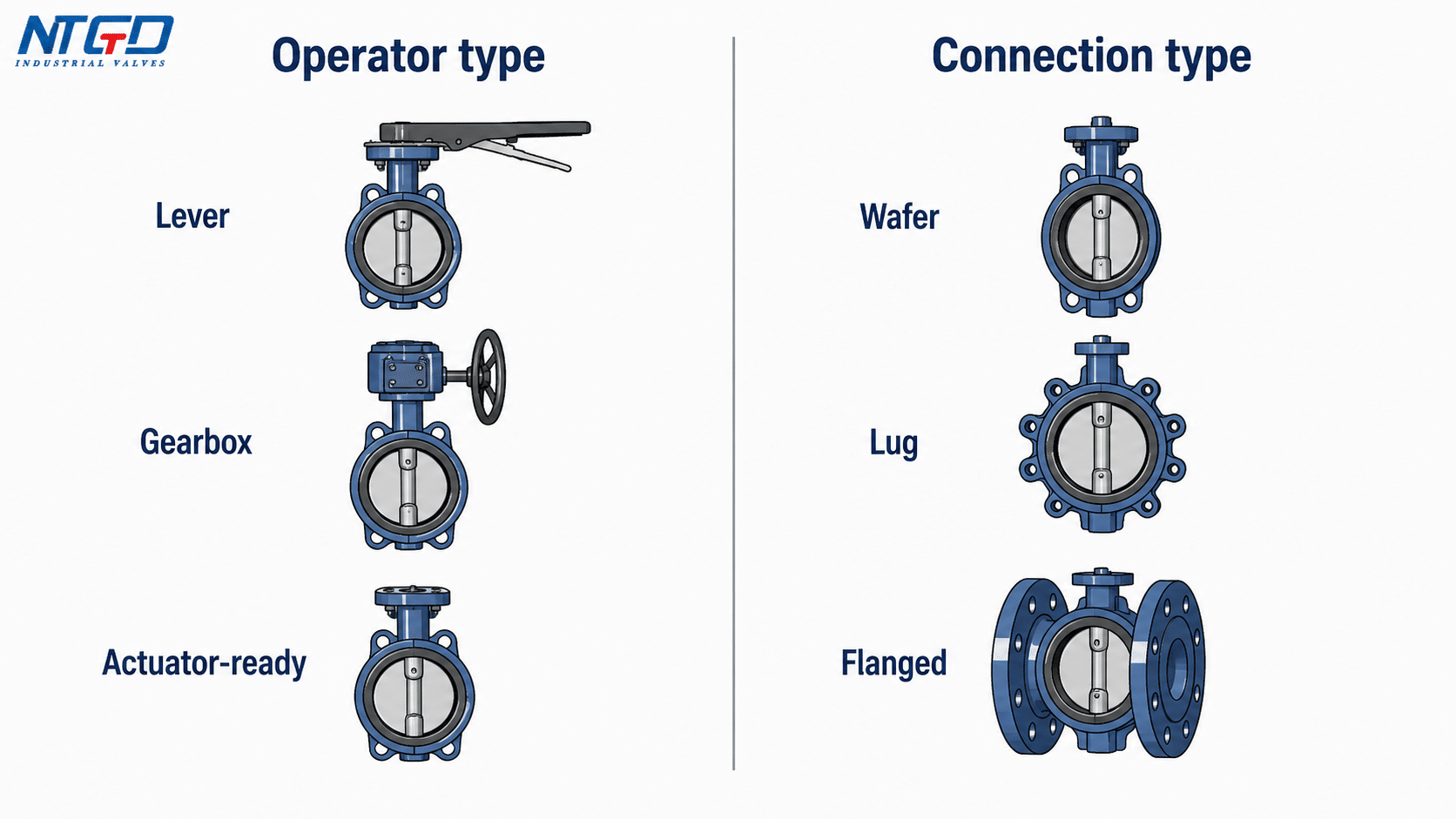
Operator Type vs Connection Type: Do Not Mix These Two Classifications
| Classification | Examples | What It Describes |
|---|---|---|
| Operator type | Lever, handwheel gearbox, worm gear operator, chainwheel, electric actuator, pneumatic actuator | How the valve is operated |
| Connection / body configuration | Wafer, lug, flanged, double flanged, eccentric | How the valve body connects to the pipeline or how the disc/seat design is arranged |
A gear operated butterfly valve should be described by both its body configuration and its operator type. For example:
- gear operated wafer butterfly valve;
- gear operated lug butterfly valve;
- gear operated flanged butterfly valve;
- worm gear operated butterfly valve.
This article focuses on manual gear operator selection for butterfly valves. Electric, pneumatic, and hydraulic actuators are separate operation categories and should be evaluated separately when remote control, automation, fail-safe position, or signal feedback is required.
Common Operator Options for Gear Operated Butterfly Valves
| Operator / Gear Option | Main Use | Caution |
|---|---|---|
| Worm gear operator | Most common manual gearbox for butterfly valves | Gear ratio and torque capacity must match the valve |
| Chainwheel operation | Useful where the valve is high or hard to reach | Requires safe access and proper installation layout |
| Lockable gear operator | Helps prevent unauthorized or accidental operation | Locking arrangement must match site safety practice |
| Gearbox with position indicator | Helps operators confirm disc position | Indicator must be aligned with actual disc position |
| Actuator-ready mounting interface | Allows future automation planning | This only means the valve may support future automation planning; this article still focuses on manual gear operator selection |
Electric and pneumatic actuators are adjacent operation options, but they are not the main subject of this article. They should be reviewed separately when remote control, automation, fail position, signal feedback, or fast cycling is required.
Common Connection Configurations
| Configuration | How It Connects | Typical Use | Selection Caution |
|---|---|---|---|
| Gear operated wafer butterfly valve | Clamped between two pipe flanges | Compact installation and general utility service | Requires correct flange alignment and bolt tightening |
| Gear operated lug butterfly valve | Uses threaded or through-bolt lug-style body | Piping systems where one side may need removal in some designs | Dead-end service capability depends on manufacturer design |
| Gear operated flanged butterfly valve | Has integral flanged ends | Larger sizes or applications needing more rigid flange connection | Face-to-face and flange standard must match the pipeline |
| Gear operated double flanged butterfly valve | Flanged on both sides with more robust body structure | Large-diameter water, wastewater, and industrial pipelines | Weight, installation space, and support must be reviewed |
| Eccentric / double eccentric gear operated butterfly valve | Disc and shaft geometry reduce seat friction in many designs | Higher-performance shutoff or larger industrial service | Seat design, sealing direction, and torque data must be confirmed |
These configurations should be selected based on pipe design, pressure class, service medium, installation space, and maintenance access.
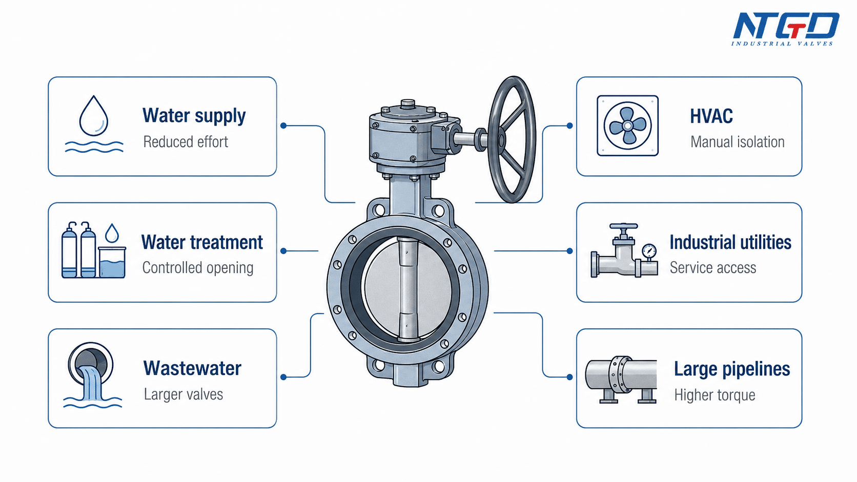
Applications and Service Fit for Gear Operated Butterfly Valves
Gear operated butterfly valves are often used where manual operation is still preferred, but direct lever operation is not practical.
| Application / Service | Why Gear Operation Fits | Caution / Not Ideal Condition |
|---|---|---|
| Water supply systems | Large pipe sizes and moderate operating frequency often benefit from reduced handwheel effort | Confirm seat material, pressure rating, and maximum operating pressure to avoid leakage or premature valve damage |
| Water treatment plants | Controlled opening and closing helps operators manage flow changes | Media may contain solids or chemicals; material compatibility and seat wear should be reviewed |
| Wastewater systems | Gear operation can help on larger valves and difficult-to-operate lines | Debris, corrosion, and seat wear require inspection planning |
| HVAC and cooling water | Manual control may be needed on larger chilled water or cooling water lines | Not a substitute for automated control where remote modulation is required |
| Industrial utilities | Suitable for air, water, cooling, and utility lines where manual operation is acceptable | Confirm medium, temperature, cycling requirements, and gearbox accessibility |
| Power plant auxiliary systems | Larger utility lines may require gearbox operation for safer manual handling | Project specifications and testing requirements must be checked |
| Chemical processing | Gear operation can help with controlled manual isolation | Material compatibility, operating frequency, and service temperature should be reviewed carefully |
| Large-diameter pipelines | Higher operating torque often makes gearbox operation practical | Support, access, gearbox orientation, and installation clearance are important |
| Moderate throttling / isolation service | Gearbox allows gradual disc positioning | A butterfly valve is not automatically a precision control valve |
A gear operated butterfly valve is often a good fit for manual isolation and coarse regulation on medium to large pipelines. For high-frequency automation, tight control loops, or remote operation, pneumatic or electric actuation may be more suitable.
Advantages and Limitations of Gear Operated Butterfly Valves
Gear operation improves manual usability, but it also adds mechanical complexity. Selection should consider both sides.
| Factor | Advantage | Limitation / Caution |
|---|---|---|
| Operating torque | Reduces manual effort by using gear reduction | Gearbox must be sized for actual valve torque |
| Operating control | Allows slower and more gradual opening / closing | Slower than direct lever operation |
| Larger valve sizes | More suitable than lever operation when torque is high | Larger gearbox may add weight and space requirements |
| Operator safety | Can reduce sudden movement and excessive manual force | Safe access to handwheel is still required |
| Position holding | Worm gear and travel stops can help hold position | Indicator and stops must be checked and maintained |
| Cost | Adds operational convenience for suitable services | Typically higher than lever operation, depending on valve size and gearbox design |
| Maintenance | Gearbox may make difficult manual operation easier | More mechanical parts require inspection, especially in wet, outdoor, corrosive, or high-cycle services |
| Flow control | Supports moderate regulation and controlled manual positioning better than a direct lever | For precision flow control, review a dedicated control valve or actuator / positioner solution where required |
| Installation | Can reduce lever swing space | Gearbox orientation and handwheel access must be considered |
When Another Operation Method May Be Better
A different operation method may be better when:
- the valve is small and easy to operate by lever;
- very fast manual shutoff is required;
- remote operation is required;
- automatic fail-open or fail-close function is required;
- frequent cycling would make manual operation inefficient;
- precise control duty is required.
In these cases, lever, pneumatic, electric, or control valve solutions may need to be reviewed separately.
Troubleshooting Gear Operated Butterfly Valves
Troubleshooting should first separate gearbox problems from valve sealing or pipeline problems. A hard-to-turn handwheel is not always a gearbox failure. Internal leakage is not always caused by the gear operator.
All troubleshooting should follow the manufacturer’s operation and maintenance instructions and the site’s safety procedure. The table below is an initial diagnostic guide, not a complete repair manual.
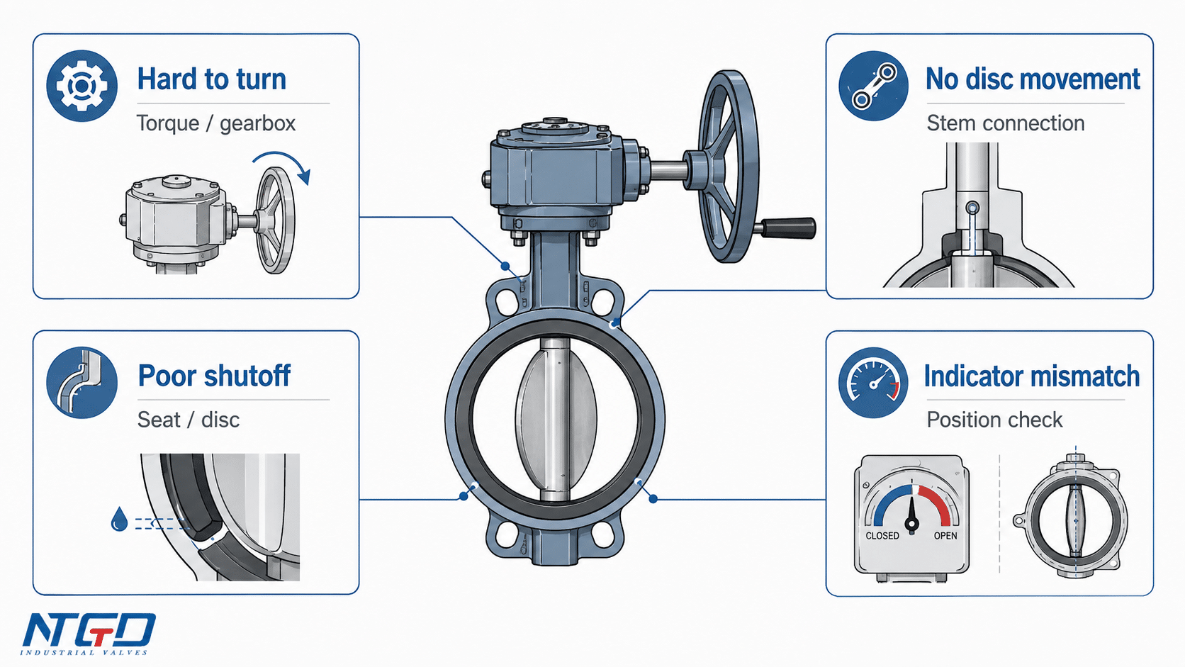
| Symptom | Possible Cause | Inspection Point | Recommended Action |
|---|---|---|---|
| Valve is hard to open or close | High operating torque, dry gearbox, corrosion, seat swelling, debris around disc | Check handwheel force, gearbox condition, line pressure, and media buildup | First review gearbox condition, lubrication status, external corrosion, and service torque conditions; then inspect valve internals if the problem remains |
| Handwheel turns but disc does not move | Damaged gear teeth, loose coupling, stem connection failure | Check stem movement and position indicator response | Stop operation and inspect the gearbox-stem connection before applying more force |
| Valve cannot fully open or close | Travel stop misadjustment, obstruction, seat damage, disc misalignment | Check travel stops, disc position, and pipeline debris | Adjust stops only according to manufacturer instructions; inspect seat and disc if closure remains poor |
| Position indicator does not match flow condition | Indicator misalignment or gearbox/stem issue | Compare indicator position with actual valve response | Recalibrate or inspect gearbox and stem connection |
| Gearbox rattles, wobbles, or has excessive backlash | Gear wear, loose fasteners, damaged bearing, poor mounting | Check mounting bolts, handwheel play, gearbox housing, and abnormal noise | Tighten external fasteners if allowed by the manual; otherwise inspect or replace worn components |
| Gearbox corrosion or water ingress | Outdoor exposure, poor sealing, damaged coating | Check gearbox housing, seals, and lubricant condition | Review gearbox protection, sealing condition, and maintenance requirement; severe corrosion should be evaluated before further operation |
| Internal leakage through valve | Seat wear, disc damage, debris, incorrect closure, wrong material | Check disc/seat contact and service media | Inspect seat and disc; confirm valve selection and service compatibility |
| External leakage at flange area | Gasket issue, flange misalignment, uneven bolting | Check flange joint and gasket condition | Reinstall or replace gasket according to project procedure |
| Leakage around stem area | Stem seal or packing wear | Check stem area for leakage during operation | Inspect seal design and replace parts if required |
| Valve opens or closes unevenly | Stem/disc misalignment, gearbox issue, uneven seat load | Check operation smoothness and pipeline stress | Inspect installation alignment and valve condition |
Gearbox Problems vs Valve Sealing Problems
A gearbox controls movement. It does not create the main sealing performance of the valve. Shutoff depends mainly on the disc, seat, stem alignment, pressure direction, installation, and service condition.
This distinction matters during troubleshooting:
- If the handwheel feels heavy but the valve position changes normally, first review gearbox condition, lubrication, corrosion, and actual operating torque.
- If the handwheel moves normally but shutoff is poor, inspect the seat, disc, gasket, and stem sealing before assuming the gearbox is the root cause.
- If leakage occurs outside the valve, inspect flange gaskets, stem seals, and installation alignment.
- If the position indicator is wrong, inspect the gearbox-stem relationship before assuming the valve is open or closed.
Separating gearbox mechanical issues from valve sealing issues can shorten field diagnosis and reduce unnecessary replacement decisions.
RFQ Checklist and FAQ for Gear Operated Butterfly Valves
Before requesting a gear operated butterfly valve quotation or technical review, prepare the following information.
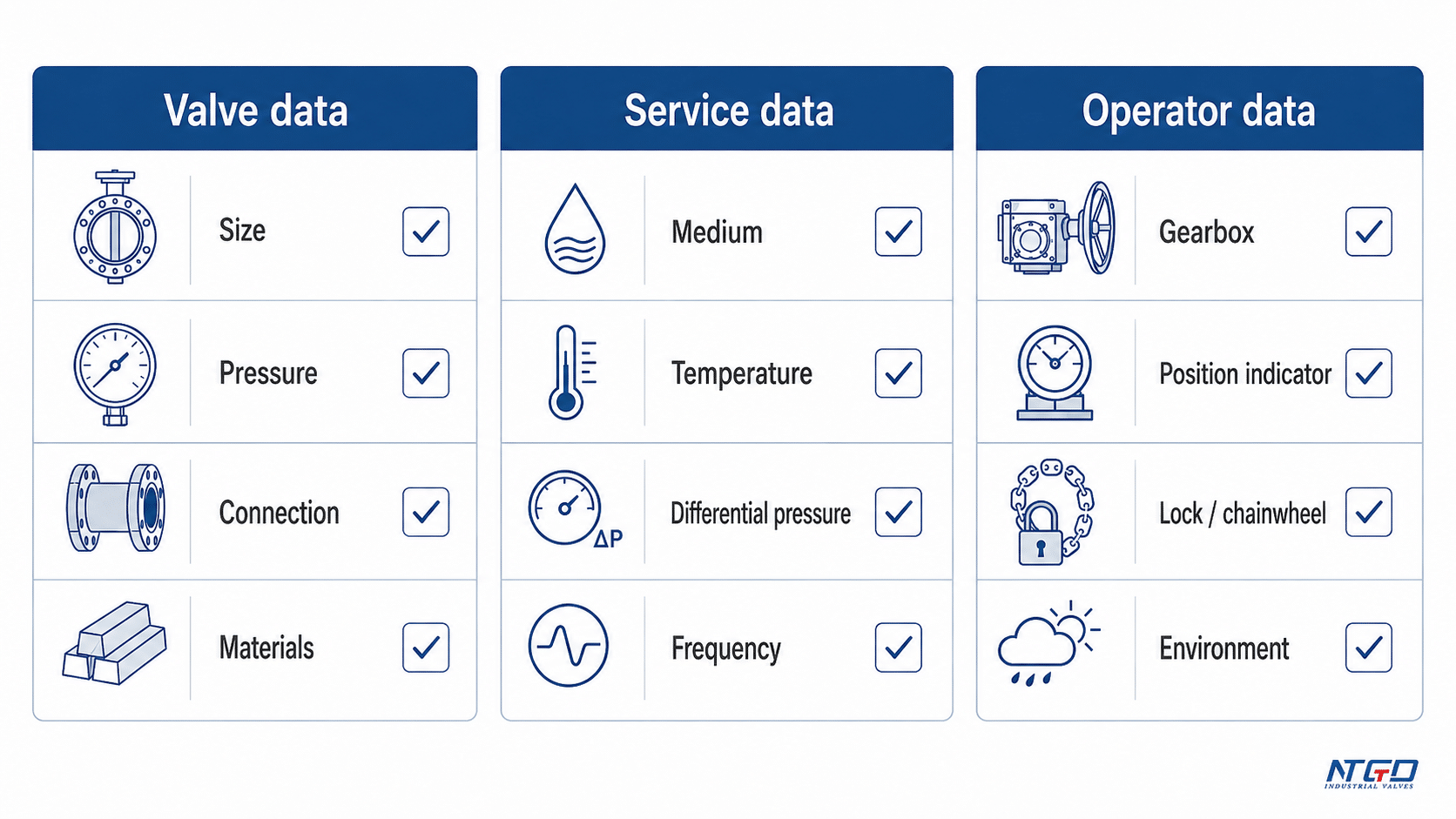
| RFQ Item | Why It Matters |
|---|---|
| Valve size | Affects torque, body design, gearbox selection, and installation space |
| Pressure class / rating | Determines pressure boundary and seat load requirements |
| Connection type | Wafer, lug, flanged, double flanged, or other configuration |
| Body material | Must match pressure, environment, and corrosion conditions |
| Disc material | Affects corrosion resistance, flow exposure, and durability |
| Stem material | Important for torque transmission and corrosion resistance |
| Seat / liner material | Affects sealing, temperature range, chemical compatibility, and operating torque |
| Medium | Determines material compatibility and potential debris / corrosion risk |
| Temperature | Affects seat material and sealing performance |
| Pressure differential | Strongly affects operating torque |
| Operating frequency | Helps decide whether manual gear operation is suitable |
| Gearbox / gear operator requirement | Determines handwheel, gear ratio, torque capacity, and mounting interface |
| Position indicator requirement | Useful for field operation and confirmation |
| Lock / chainwheel / extension need | Depends on site access and safety practice |
| Indoor / outdoor / corrosive environment | Affects gearbox housing, coating, and protection requirements |
| Testing or standard requirement | Must follow project specification and applicable valve standards |
| Datasheet or drawing requirement | Helps verify dimensions, materials, and installation compatibility |
FAQ
What is a gear operated butterfly valve?
A gear operated butterfly valve is a butterfly valve opened and closed by a manual gearbox and handwheel. The gearbox increases output torque and turns the stem, which rotates the disc inside the valve body.
Is a gear operated butterfly valve the same as a butterfly valve with a gearbox?
In most practical discussions, yes. A butterfly valve with a gearbox is commonly called a gear operated butterfly valve or gearbox operated butterfly valve. The complete valve includes the body, disc, seat, stem, and mounted gear operator.
What is a gear operator for a butterfly valve?
A gear operator for a butterfly valve is the manual gearbox assembly mounted on the valve top works. It connects the handwheel to the stem and helps rotate the disc with less manual effort.
Why do some handwheel butterfly valves need a gearbox while others do not?
A handwheel alone does not always mean the valve has gear reduction. Small or low-torque butterfly valves may be operated directly by a lever or simple manual device. Larger valves, tighter seats, higher pressure differential, or difficult access may require a gearbox so the handwheel can turn the stem with more torque and better control.
What is the difference between gear operated and lever operated butterfly valves?
A lever-operated butterfly valve directly turns the stem with a handle. A gear operated butterfly valve uses a handwheel and gearbox to turn the stem. Gear operation is slower but easier for larger or higher-torque valves.
When should a butterfly valve use a gearbox?
A butterfly valve should use a gearbox when direct lever operation would require too much force, when smoother operation is needed, when the valve is larger, or when pressure differential and seat design increase operating torque.
Can the gearbox be replaced?
A gearbox may be replaceable on some valve designs, but it is not a universal part. Replacement depends on stem size, mounting interface, torque rating, gearbox design, and manufacturer compatibility. An incorrect replacement may cause operating failure, inaccurate position indication, stem damage, or gearbox damage.
What causes a gear operated butterfly valve to be hard to turn?
Common causes include high line torque, dry or corroded gearbox components, seat swelling, debris around the disc, travel stop misadjustment, or stem/disc alignment issues.
How often should the gearbox on a gear operated butterfly valve be inspected?
Inspection frequency should follow the manufacturer’s operation and maintenance instructions and the actual service severity. Outdoor, wet, corrosive, high-cycle, or high-torque services usually require closer inspection. Common checks include lubrication condition, fasteners, corrosion, backlash, position indicator alignment, and travel stop condition.
Are gear operated butterfly valves suitable for throttling?
They can be used for moderate regulation in some services because the gearbox gives more gradual movement than a lever. For precision flow control, the valve design, operating range, actuator arrangement, and control requirements should be reviewed separately.
What information should be provided before requesting a quote?
Provide valve size, pressure rating, connection type, materials, medium, temperature, pressure differential, operating frequency, service environment, and any gearbox, position indicator, lock, chainwheel, or datasheet requirements.
Conclusion
A gear operated butterfly valve is selected when a butterfly valve needs safer, easier, and more controlled manual operation than a direct lever can provide. The gearbox does not change the basic butterfly valve principle: the disc still rotates 90 degrees. It changes how torque is applied to the stem and how gradually the valve moves.
For the right service, gear operation can reduce manual effort, improve position control, and make larger butterfly valves easier to handle. For small, low-torque valves, a lever may still be simpler and more economical.
Final butterfly valve selection should be based on valve size, operating torque, pressure differential, seat design, operating frequency, installation access, service environment, and project specification. Matching these factors to a specific project is where application review can help.
If you are selecting a gear operated butterfly valve for an industrial pipeline, prepare the valve size, pressure class, connection type, materials, medium, temperature, pressure differential, and operator requirements before inquiry. NTGD can review these service conditions and help match the valve body configuration and gear operator arrangement to the actual operating requirements.
