Author Name: Bruce Zheng
Author Role: Co-Founder and Valve Engineer at NTGD Valve
Author Bio: Bruce Zheng is Co-Founder and Valve Engineer at NTGD Valve, focusing on industrial valve selection, application, and technical content for global B2B buyers.
Last Updated: June 3, 2026
How does a gate valve work? A gate valve uses multi-turn stem motion to lift or lower a gate or wedge across the flow path. When the gate is fully raised, the valve provides an open passage; when the gate is lowered into the seats, it creates shutoff for isolation service.
This mechanical principle makes a gate valve suitable for on-off isolation service, not continuous throttling. Fully open, the gate moves out of the bore and allows flow to pass through with low resistance. Fully closed, the gate or wedge contacts the valve seats and blocks the flow path.
In industrial service, the working principle is simple to describe but important to apply correctly. Shutoff reliability depends on how the stem, gate or wedge, seats, packing, body and operating device work together under real media, pressure and temperature conditions.
What Is a Gate Valve?
A gate valve is a linear-motion isolation valve used to start or stop flow in a pipeline. Unlike a ball valve or butterfly valve, which uses quarter-turn rotation to move the closing element, a gate valve uses multi-turn operation to move the gate in a straight line.
In a typical industrial gate valve, the closing element moves perpendicular to the flow direction. When the gate is lifted, the flow path opens. When the gate is lowered into the seat area, the flow path closes.
This article focuses on the generic working principle of industrial gate valves. Wedge-specific designs, knife gate valves, high-pressure gate valves, forged steel gate valves and actuator sizing are related topics, but they should be handled in dedicated product or technical pages rather than expanded inside this working principle guide.
For industrial service, this makes the gate valve suitable for:
- full-open flow service;
- full-closed shutoff service;
- pipelines where low pressure loss is preferred when the valve is open;
- applications where frequent throttling is not required.
The key operating boundary is clear: a gate valve is designed to isolate the line. It is not designed to precisely regulate flow.
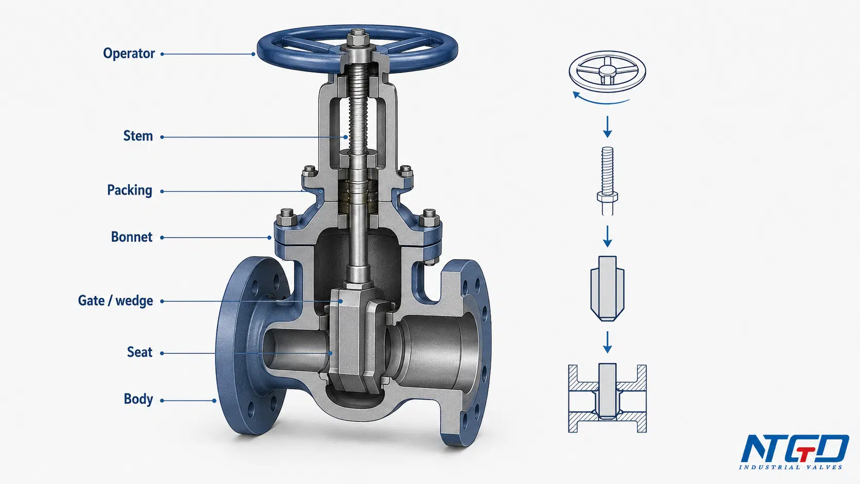
Main Components Involved in the Working Principle
A gate valve has many parts, but the table below only lists the core components directly involved in the working principle. It is not a complete parts list.
| Component | Role in the Working Principle | What Happens During Operation | Notes / Boundary |
|---|---|---|---|
| Body | Contains the flow passage and pressure boundary | Fluid passes through the body bore when the valve is open | Body design affects pressure class and end connection, but body design is not expanded here |
| Bonnet | Covers the upper valve chamber and supports the stem assembly | The gate may move upward into the bonnet area when the valve opens | Bonnet types belong to a separate design topic |
| Handwheel / actuator | Provides the input motion | The operator turns the stem directly or through a gear or actuator | Manual, gear, electric or pneumatic input may differ, but the internal principle remains similar |
| Stem | Transfers motion from the operator to the gate or wedge | Threaded stem motion converts rotation into controlled vertical travel | Stem type affects whether the valve position is visually obvious |
| Gate / wedge | Main closing element | Moves up to open the flow path and down to contact the seats for shutoff | Wedge shape may vary by design, but detailed wedge type selection belongs elsewhere |
| Seat / seat rings | Provide the sealing interface | The gate or wedge contacts the seats when closing | Seat condition directly affects shutoff performance |
| Packing / sealing area | Helps seal around the stem | Reduces leakage around the moving stem area | Packing details belong to maintenance and design topics |
For a deeper breakdown of body, bonnet, stem, gate or wedge, seat, packing and operating-device functions, use NTGD’s gate valve parts and components guide after this working-principle overview.
These components should be read as a working system, not as isolated parts. The handwheel or actuator supplies motion, the stem controls travel, the gate or wedge changes the flow path, and the seats provide the sealing interface. Shutoff reliability depends on the alignment between stem travel, gate movement and seat contact.
Gate Valve Working Principle: From Rotary Input to Linear Gate Movement
The gate valve working principle is based on a mechanical conversion:
rotary input → threaded stem movement → linear gate movement → open or closed flow path
In most manual gate valves, the operator turns a handwheel. This rotary motion is transferred to the stem. Through the stem threads, rotation is converted into linear travel. The gate or wedge then moves vertically inside the valve body.
| Step | Mechanical Action | Component Involved | Result in Flow Path |
|---|---|---|---|
| 1 | Operator applies rotary input | Handwheel, gear operator or actuator | The valve begins to move from its current position |
| 2 | Rotation is transferred to the stem | Stem and stem threads | Rotary motion becomes controlled linear travel |
| 3 | Stem movement drives the gate or wedge | Stem, gate or wedge | The closing element moves up or down |
| 4 | Gate position changes the bore opening | Gate / wedge and valve body | Flow path becomes open, partially obstructed or closed |
| 5 | Gate or wedge contacts the seat during closure | Gate / wedge and seat rings | Shutoff is created when seat contact is achieved |
These five steps describe the common internal logic of gate valve operation. The external input may be manual, gear-operated, electric or pneumatic, but the internal mechanical chain remains based on controlled gate travel and seat contact.
How the Threaded Stem Converts Rotation into Travel
The threaded stem is the core motion-conversion part. When the operator turns the handwheel, the stem thread controls how the gate moves upward or downward. The exact mechanical arrangement depends on the stem design, but the principle remains the same: rotation is converted into controlled linear motion.
This is why gate valves usually require multiple turns to open or close. They are not quick-opening quarter-turn valves. The number of turns depends on valve size, stem pitch, gear ratio and manufacturer design.
This multi-turn linear motion also affects system planning. A gate valve may be reliable for isolation, but it is usually slower to operate than a quarter-turn valve. For emergency shutoff, remote operation or large-size valves, operation time and actuator selection should be reviewed during specification.
How the Gate or Wedge Moves Across the Flow Path
Inside the valve body, the gate or wedge moves in a straight path relative to the flow. It does not rotate into the flow like a ball valve. It does not swing like a check valve. It does not pivot like a butterfly valve.
Instead, the gate or wedge travels vertically:
- upward movement opens the flow path;
- downward movement closes the flow path;
- final downward travel brings the gate or wedge into the seat area.
This vertical movement is the mechanical reason a gate valve is described as a linear-motion isolation valve. Because the gate moves out of the bore when fully open, the valve can provide a relatively unobstructed flow path. The same linear travel also means the opening and closing stroke is longer than in a quarter-turn valve.
Gate Valve Operation: How It Opens and Closes
Gate valve operation can be explained in two directions: opening and closing. The operating device may be a handwheel, gear operator, electric actuator or pneumatic actuator, but the internal logic remains focused on stem movement, gate travel and seat contact.
Opening Sequence
When a gate valve opens, the operator turns the handwheel or actuator in the opening direction specified by the valve marking, datasheet or manufacturer’s instruction. The stem then moves the gate or wedge upward.
As the gate rises, it moves away from the seat area and out of the flow path. Once the valve is fully open, the bore becomes largely unobstructed. This is the condition where the gate valve offers low flow resistance compared with a partially open position.
A simplified opening sequence is:
- Operator applies opening input.
- Stem thread converts rotation into vertical movement.
- Gate or wedge lifts away from the seats.
- Flow path becomes increasingly open.
- Fully open position provides a clear passage through the valve body.
The fully open position matters because the gate edge is removed from the main flow path. This reduces direct high-velocity impact on the closing element and supports stable isolation service when the valve is correctly selected and sized.
Closing Sequence
When a gate valve closes, the operator turns the handwheel or actuator in the closing direction specified for that valve. The stem moves the gate or wedge downward.
As the gate approaches the seat area, the flow path becomes restricted. At the final stage, the gate or wedge enters the seating area and contacts the valve seats. Proper shutoff depends on this seating contact.
A simplified closing sequence is:
- Operator applies closing input.
- Stem drives the gate or wedge downward.
- The gate moves into the flow path.
- The gate or wedge contacts the seat surfaces.
- The valve reaches the fully closed position and blocks flow.
If final seat contact is incomplete, the valve may appear closed from the outside but still leak internally. This is why seat condition, gate alignment and correct operation are critical for reliable isolation.
Manual, Gear and Actuated Operation: Same Internal Principle
Different operation methods change how the input motion is supplied. They do not change the basic internal working principle.
| Operation Method | Input Source | Internal Principle | When Used | Boundary |
|---|---|---|---|---|
| Manual handwheel | Human operator | Handwheel turns the stem, stem moves the gate | Smaller valves or accessible locations | Not a fast quarter-turn operation |
| Gear operator | Handwheel plus gearbox | Gear reduces effort and drives the stem | Larger valves or higher torque demand | Gear dimensions are not covered here |
| Electric actuator | Motorized input | Actuator rotates or drives the stem mechanism | Remote or automated operation | Actuator sizing is a separate topic |
| Pneumatic actuator | Air-powered input | Actuator supplies controlled motion to operate the valve | Automated systems where pneumatic supply is available | Pneumatic actuator design is not covered here |
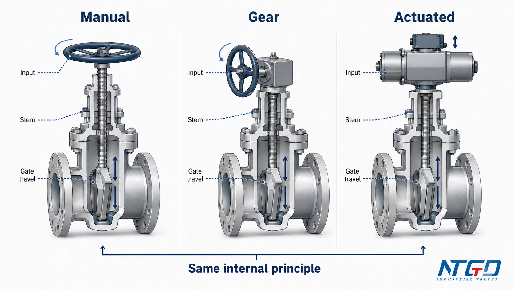
Regardless of the operation method, a gate valve still requires controlled multi-turn or stroke travel to complete the full open-close cycle. An actuator can automate the input, but it does not change the internal gate travel and seat-contact logic.
Open, Partially Open and Closed Positions
The table below compares the three main operating states of a gate valve. It helps explain the difference between correct isolation service and the common mistake of using a gate valve as a throttling device.
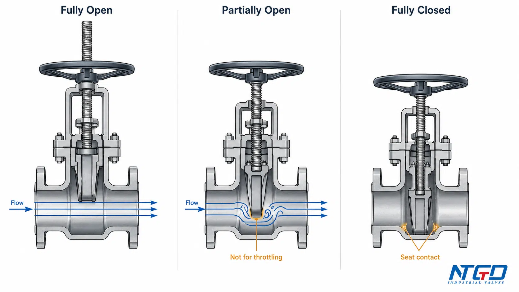
| Valve Position | Gate / Wedge Position | Flow Path | Seat Contact | Recommended Use | Risk |
|---|---|---|---|---|---|
| Fully open | Gate / wedge lifted out of the bore | Flow path is clear and resistance is relatively low | No shutoff contact | Recommended for normal flow service | Low resistance when correctly sized |
| Partially open | Gate / wedge remains inside part of the flow path | Flow is restricted and disturbed | Usually not fully seated | Not recommended for normal throttling | Turbulence, vibration, erosion, seat / gate wear |
| Fully closed | Gate / wedge lowered into the seat area | Flow path is blocked | Seat contact creates shutoff | Recommended for isolation | Shutoff depends on seat condition, gate alignment and design |
Why Fully Open Is Preferred for Flow
When a gate valve is fully open, the gate is lifted away from the main flow path. This creates a more direct passage through the valve body. In many industrial pipelines, this is the main advantage of gate valve operation: low resistance when the valve is open.
This does not mean every gate valve has identical pressure-drop behavior. Actual flow performance depends on size, bore design, pressure class, internal geometry and project specification. However, the working principle supports low-resistance isolation better than fine flow regulation.
Why Partially Open Is Not Recommended
A partially open gate valve leaves the gate or wedge in the flow path. Fluid can strike the edge of the gate, creating unstable flow, vibration and localized erosion. The relationship between stem travel and flow rate is not precise enough for control duty.
Extended operation in the partially open position can damage the gate and seat surfaces. Over time, this may reduce shutoff tightness even when the valve is later moved to the fully closed position. In critical isolation service, loss of shutoff reliability can create leakage risk, contamination risk or unplanned maintenance.
This is why a gate valve should not be selected as a throttling valve. If the system requires continuous flow modulation, pressure control or frequent adjustment, a valve designed for control duty should be reviewed.
Wedge Movement, Seat Contact and Shutoff Principle
The gate or wedge is the closing element that creates shutoff when it moves into the seat area. In many industrial gate valves, the closure element is wedge-shaped. During closing, the gate or wedge moves downward and contacts the seats inside the valve body.
Shutoff is not created simply because a metal part blocks the flow path. It is created when the closing element reaches the seat area and forms sealing contact with the seat surfaces.
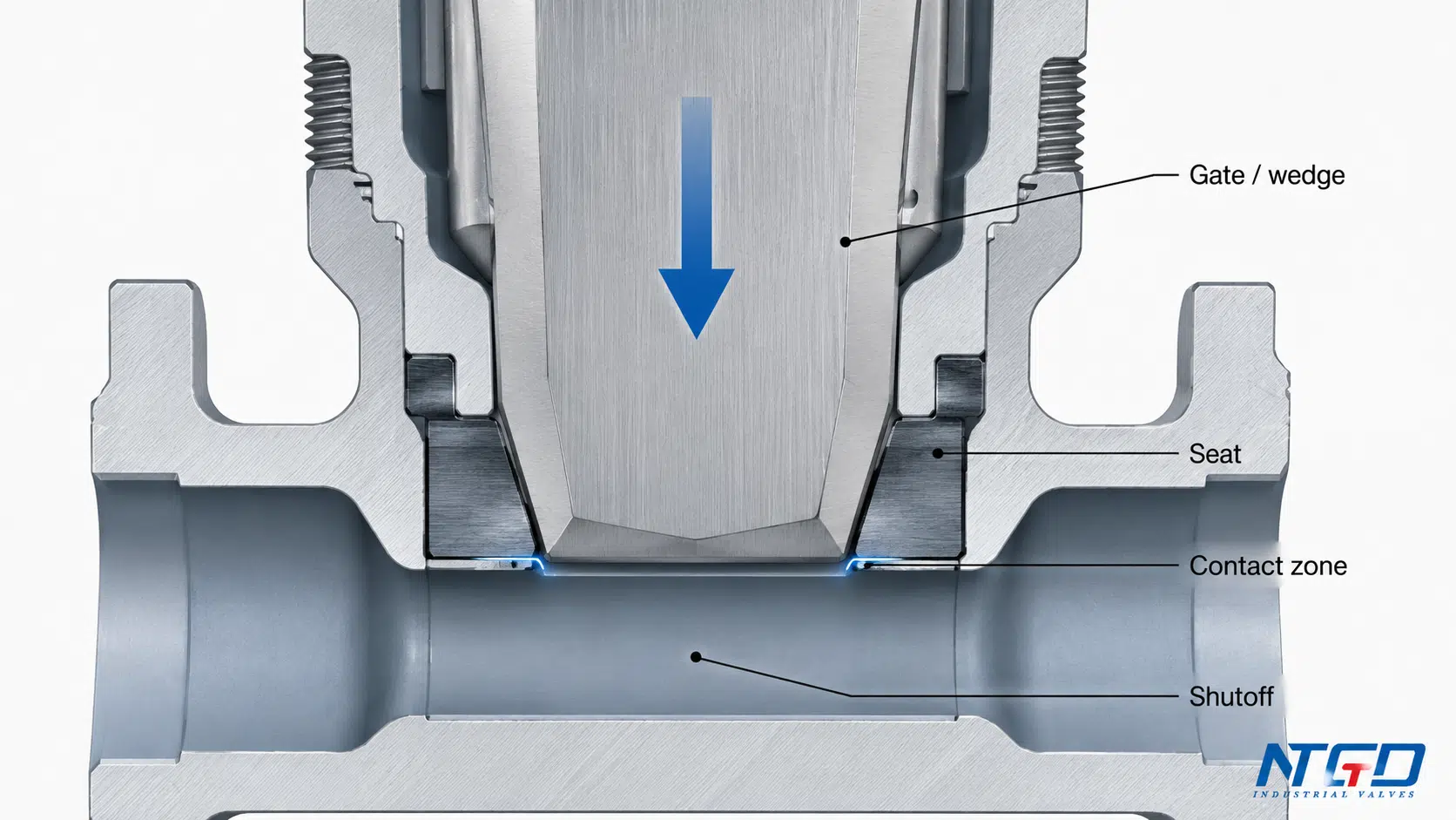
What Happens Near the Seat During Closing
Near the end of the closing stroke, the gate or wedge approaches the seat rings. The final seating action creates contact pressure between the closing element and the seat surfaces. This contact pressure allows the valve to isolate the line.
If contact pressure is insufficient, the valve may not achieve reliable shutoff even if the gate has reached the closed position. Debris near the seat, damaged seating surfaces, poor alignment or incorrect operation can all affect shutoff performance. These conditions belong to maintenance and troubleshooting, but they explain why the seat area is central to the working principle.
Why Gate / Wedge Design May Vary
Different gate valves may use different gate, wedge or disc designs. Wedge gate valves use a wedge-shaped closing element, while other designs, such as parallel slide or slab-type gate valves, achieve shutoff with different internal arrangements.
This article does not compare those designs in detail. The generic working principle remains narrower:
the closing element moves across the flow path, reaches the seat area, and creates shutoff through seat contact.
Detailed solid wedge, flexible wedge, split wedge, slab gate or parallel slide selection belongs in a dedicated gate valve design or selection guide.
If the selection question is specifically about rigid or more tolerant wedge behavior, route that decision to NTGD’s solid vs flexible wedge gate valve guide instead of expanding the wedge comparison inside this article.
Why Gate Valves Are Not Used for Throttling
Gate valves are commonly misunderstood as general “flow control” valves. In industrial selection, this is risky. A gate valve is mainly an isolation valve. It should normally be operated fully open or fully closed.
A partially open gate valve can create several problems:
- Turbulence: the gate edge disturbs the flow path.
- Vibration or chatter: unstable flow can cause the gate to vibrate.
- Erosion: high-velocity flow can attack the gate or seat surfaces.
- Seat wear: repeated partial opening can damage sealing areas.
- Unstable control: stem travel does not provide precise proportional flow control.
- Reduced shutoff reliability: worn gate or seat surfaces can prevent tight closure later.
This boundary is consistent with an engineering handbook discussion of gate valve limitations, which describes nonlinear opening behavior, vibration in partially open positions, and disk / seat wear when gate valves are used for regulation.
The engineering consequence is not limited to poor flow control. Long-term partial opening can reduce the valve’s ability to isolate the pipeline when shutoff is later required. For continuous modulation, a control valve or another valve type designed for throttling duty should be considered.
If the system requires flow regulation instead of simple isolation, compare the functional boundary in NTGD’s globe valve vs gate valve selection guide before finalizing the valve route.
This does not mean a gate valve will fail immediately if it is briefly between positions during normal operation. The problem is using the valve intentionally and repeatedly as a throttling device.
How Stem Type Affects Open / Closed Visibility
Users often ask how to tell whether a gate valve is open or closed. The answer depends partly on the stem design.
In a rising stem gate valve, the stem rises as the valve opens. This makes the valve position easier to identify visually. If the stem is visibly raised, the valve is usually open or moving toward open, depending on the design and position marking.
In a non-rising stem gate valve, the stem rotates but does not rise visibly outside the valve. The gate moves internally, so the valve position may not be obvious from stem height alone. In that case, the operator may need a position indicator, valve tag, operating record, datasheet or manufacturer instruction.
| Stem Type | Position Visibility | Working Principle Note | Boundary |
|---|---|---|---|
| Rising stem / OS&Y | Easier to see because stem travel is visible | Stem movement gives a visual clue of opening or closing | Full comparison belongs to a separate rising vs non-rising stem guide |
| Non-rising stem | Less visually obvious from outside | Gate moves internally while stem rotation remains externally compact | Position indication may be required |
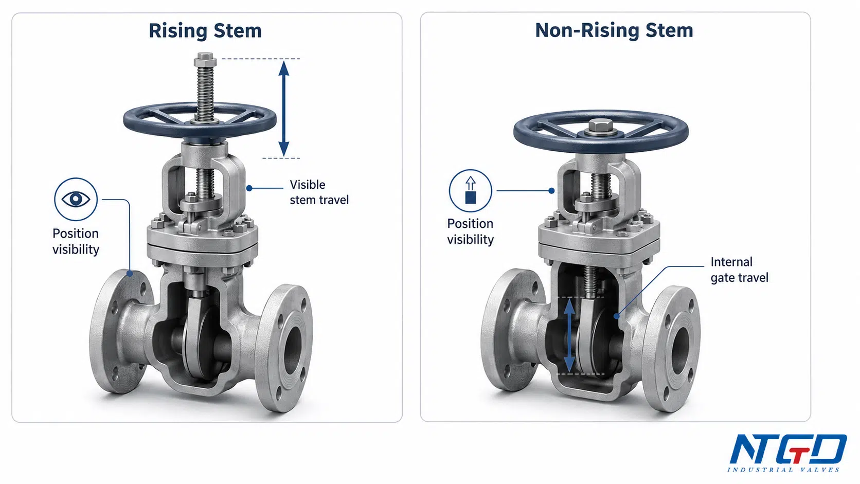
For a fuller selection-focused comparison of visible stem travel, compact installation space, thread exposure and maintenance access, see NTGD’s rising stem vs non-rising stem gate valve guide.
Regardless of stem type, the internal gate movement, seat contact and shutoff principle remain the same. Rising stem designs are often preferred when clear position visibility matters. Non-rising stem designs are often used where vertical space is limited or where external stem travel is not preferred.
Application and Specification Support for Industrial Gate Valves
Understanding how a gate valve works helps buyers and engineers prepare a better specification. The working principle affects more than the basic open / close function. It affects shutoff expectation, operation method, stem type, seating design and service suitability.
The interaction between the stem, gate or wedge and seats explains why service conditions matter. Media, pressure, temperature, size, material, seat design and operation method all affect whether a gate valve can provide reliable isolation in a real pipeline.
Before requesting a gate valve recommendation, prepare the following information.
| RFQ Item | Why It Matters for Gate Valve Selection | Example Information to Prepare |
|---|---|---|
| Media | Affects material, corrosion and erosion risk | Water, steam, oil, gas, slurry, chemical fluid |
| Pressure | Affects pressure class and body / bonnet design | Operating pressure and design pressure |
| Temperature | Affects material, packing and seat suitability | Normal and maximum operating temperature |
| Valve size | Affects operation torque, number of turns and actuator need | DN size or inch size |
| Pressure class | Defines pressure rating and flange compatibility | Class 150, 300, 600 or project-specific requirement |
| Material | Affects corrosion resistance and service life | WCB, stainless steel, forged steel, alloy material |
| Seat / wedge design | Affects shutoff behavior and service fit | Metal seat, resilient seat, wedge type if specified |
| Stem type | Affects position visibility and space requirement | Rising stem or non-rising stem |
| Operation method | Affects accessibility and automation | Manual, gear, electric or pneumatic |
| Shutoff requirement | Defines sealing expectation | Isolation duty, tight shutoff requirement, test requirement |
After these operating conditions are confirmed, the specification can be reviewed against NTGD’s industrial gate valve product range before RFQ.
For high pressure service, forged steel construction, wedge-specific selection or knife gate valve applications, the working principle should be connected to the relevant product specification rather than forced into one generic article.
FAQ
How does a gate valve open and close during operation?
A gate valve opens and closes by moving the gate or wedge up and down inside the valve body. The operator turns a handwheel, gear operator or actuator, the stem converts that input into linear travel, and the gate moves upward to open or downward into the seat area to close.
How do you know if a gate valve is open or closed?
When standing in front of a gate valve, position visibility depends on the stem design. A rising stem valve is easier to read because the stem travel is visible. A non-rising stem valve may require a position indicator, valve tag, operating record, datasheet or manufacturer instruction.
How do I know how many turns are needed to open or close a gate valve?
There is no universal number of turns. It depends on valve size, stem pitch, operator design, gear ratio and manufacturer construction. A large gate valve usually requires more turns than a small valve. The correct reference is the valve datasheet, drawing or manufacturer instruction.
Which way do you turn a gate valve to open?
Do not assume one universal clockwise or counter-clockwise rule for every industrial gate valve. The opening direction should be confirmed from the handwheel marking, valve tag, project specification, site standard or manufacturer instruction.
Can a gate valve be used for throttling?
A gate valve is not recommended for throttling. It is mainly designed for fully open or fully closed isolation service. Partial opening can create turbulence, vibration, erosion and seat / gate wear, reducing future shutoff reliability.
What does the wedge do in a gate valve?
The wedge is a closure element that moves into the seat area to create shutoff. In a wedge gate valve, the wedge-shaped gate contacts the seats when the valve closes. Detailed solid wedge, flexible wedge and split wedge selection belongs to a separate wedge gate valve topic.
What if a gate valve does not fully close?
If a gate valve does not fully close, possible causes include debris near the seat, damaged seat surfaces, stem problems, gate misalignment or packing / operating issues. For inspection and corrective actions, route this issue to NTGD’s gate valve maintenance and troubleshooting guide rather than treating incomplete closure as normal operation. This should be handled as a maintenance or troubleshooting task, not as part of the normal working principle.
Does a gate valve have a flow direction?
Some gate valves are effectively bi-directional, while others may have a preferred flow direction depending on seat design, pressure class, testing requirement or manufacturer design. If a flow arrow is present, or if the datasheet specifies an installation direction, follow the manufacturer’s documentation, drawing and project piping specification. This article focuses on working principle, not detailed flow direction rules.
Conclusion
A gate valve works by using multi-turn linear motion to move a gate or wedge across the flow path. The operator supplies rotary input, the threaded stem converts that input into linear travel, and the gate moves up or down inside the valve body. Fully open, the valve provides a clear flow path. Fully closed, the gate or wedge contacts the seats and creates shutoff.
The most important selection lesson is that a gate valve is an isolation valve. It should normally be used fully open or fully closed, not as a throttling valve. How a gate valve works directly affects shutoff reliability, operating torque, stem visibility, seat design, material suitability and operation method.
If you are selecting a gate valve for a real industrial service, prepare the operating conditions and shutoff requirements before asking for a technical recommendation. This helps the supplier or engineering team review whether a standard gate valve, wedge gate valve, forged steel gate valve, high pressure gate valve or another valve design is more suitable for the service.
