Author Name: Bruce Zheng
Author Role: Co-Founder and Valve Engineer at NTGD Valve
Author Bio: Bruce Zheng is Co-Founder and Valve Engineer at NTGD Valve, focusing on industrial valve selection, application, and technical content for global B2B buyers.
Last Updated: May 28, 2026
What Are the Main Parts of a Gate Valve?
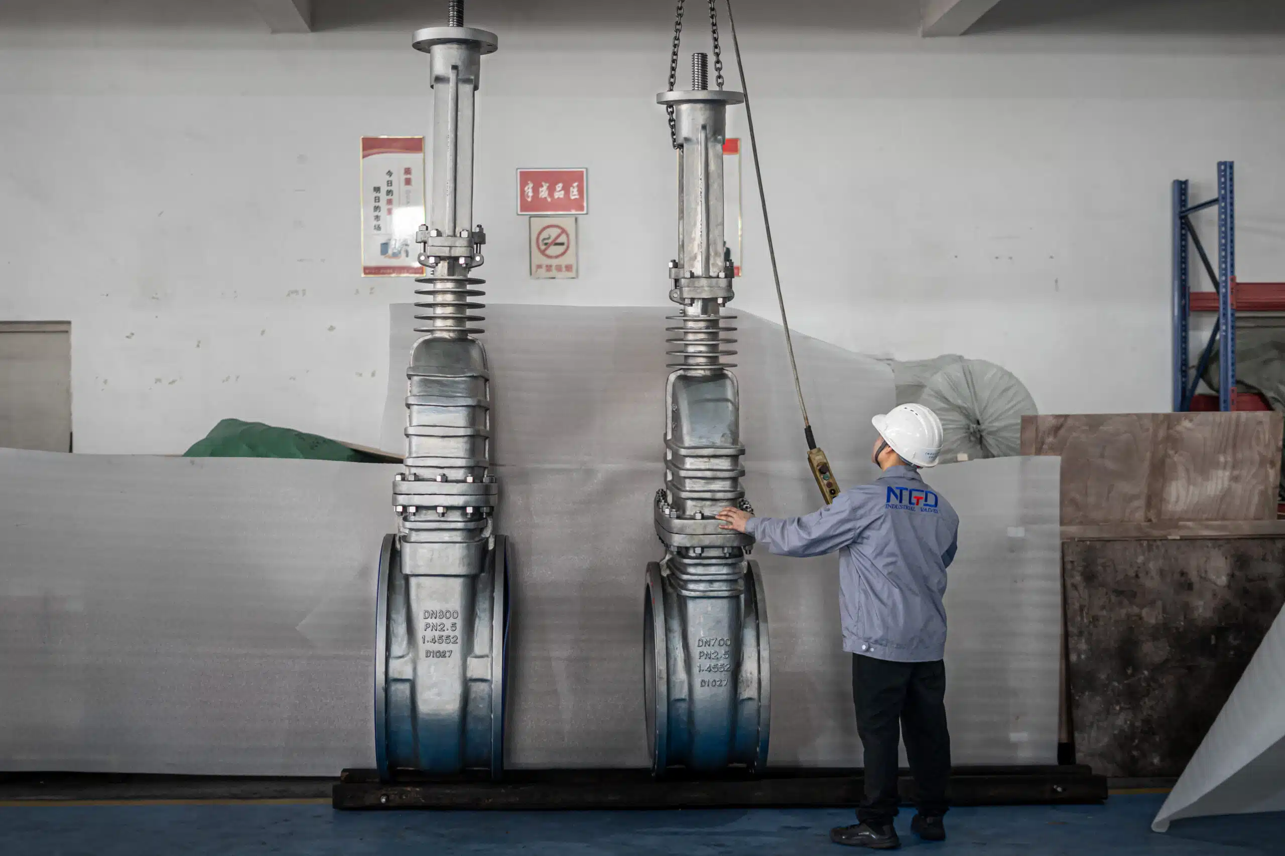
A gate valve is made of several mechanical parts that work together to open or shut off flow in a pipeline. The main gate valve parts usually include the body, bonnet, gate or wedge, seat, stem, packing, gland, gasket, and an operating device such as a handwheel, gearbox, or actuator.
In industrial service, these parts should not be viewed as a simple spare-parts list. Each component affects how the valve contains pressure, moves the gate, seals against the seat, prevents external leakage, and connects to the pipeline. For buyers and engineers, understanding these gate valve components helps when reviewing drawings, checking datasheets, preparing RFQs, or comparing different gate valve designs.
For related product specifications, NTGD’s industrial gate valve range can be reviewed after the basic part functions are understood.
Quick Answer: Gate Valve Parts at a Glance
The following list covers the main gate valve parts that an industrial buyer, engineer, or maintenance team should be able to recognize on a drawing, datasheet, or specification sheet.
The main parts of a gate valve are:
- Body — the main pressure-retaining shell connected to the pipeline.
- Bonnet — the upper pressure-retaining cover that supports the stem and packing area.
- Gate / Wedge / Disc — the moving shutoff member that rises or lowers to open or close the flow path.
- Seat / Seat Ring — the sealing surface where the gate contacts the valve body.
- Stem — the threaded or moving shaft that transfers handwheel or actuator motion to the gate.
- Packing and Gland — the sealing system around the stem that helps prevent leakage to atmosphere.
- Gasket and Bolting — the sealing and fastening parts at the body-bonnet joint.
- Handwheel, Gearbox or Actuator — the operating device used to move the stem and gate.
A typical gate valve is mainly used for fully open or fully closed service. It is not normally selected for throttling because a partially open gate can expose the seat and gate surfaces to concentrated flow, vibration, and wear.
Gate Valve Parts vs Gate Valve Components
In most industrial engineering discussions, gate valve parts and gate valve components refer to the same physical elements. The word parts is commonly used in procurement, maintenance, spare identification, and diagram-reading contexts. The word components is more often used in engineering specifications, datasheets, technical drawings, and design discussions.
For an RFQ, both terms can be used naturally. A buyer may ask for the “main gate valve parts,” while an engineer may review the “gate valve components” on a datasheet. In both cases, the important point is to identify the correct function, location, material requirement, and service condition for each part.
This article is not a brand-specific replacement parts catalog. It explains the parts of a gate valve, how they function, and what information should be confirmed before specifying an industrial gate valve.
Gate Valve Parts Diagram and Basic Structure
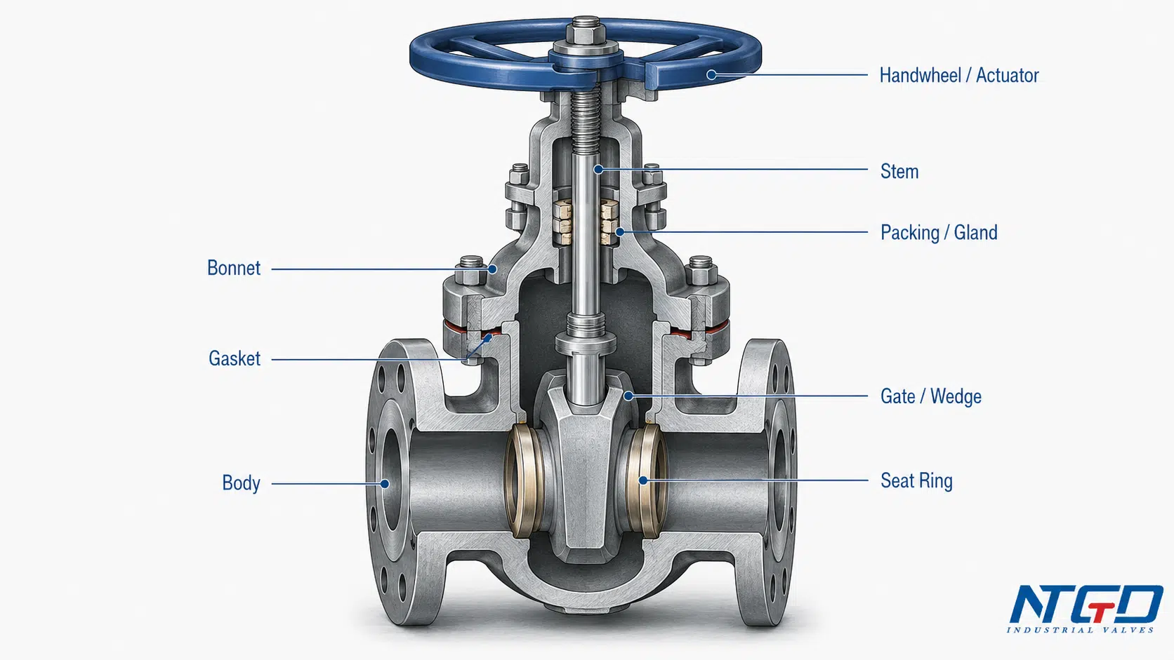
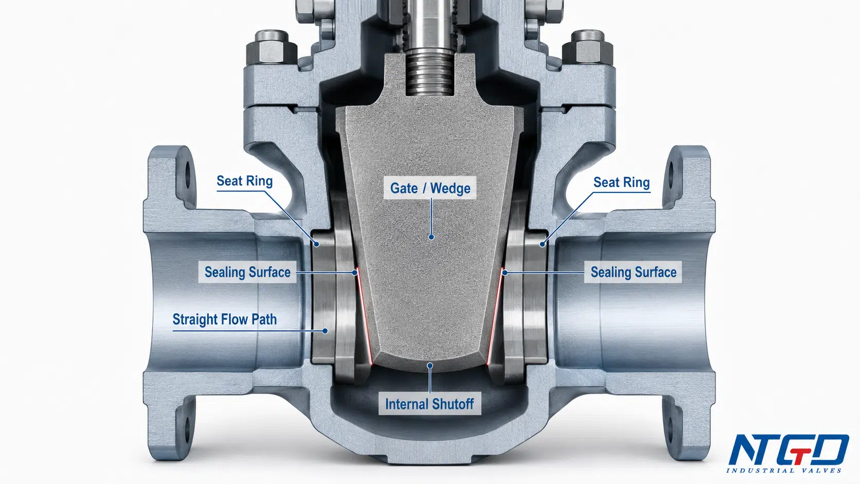
A gate valve parts diagram should show the valve body, bonnet, stem, gate or wedge, seat area, packing gland, gasket, and operating device in their correct relative positions. For a B2B technical article, a labeled cutaway diagram is more useful than a simple outside view because it shows how the internal shutoff parts relate to the external pressure boundary.
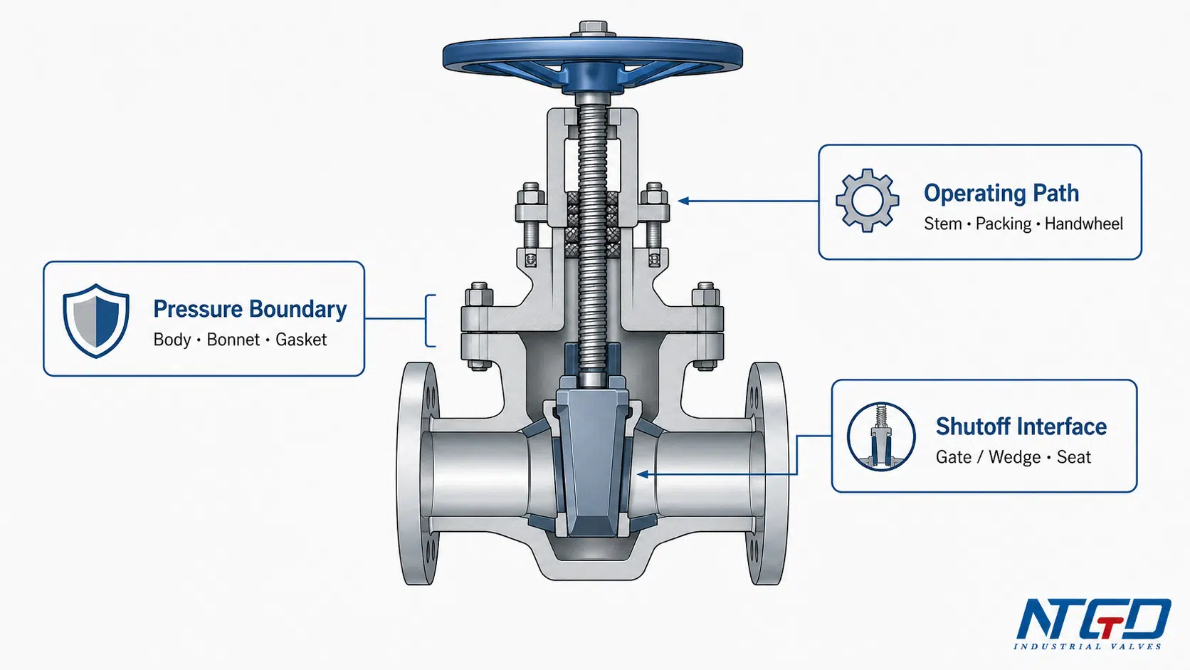
The diagram should make three basic structure zones clear:
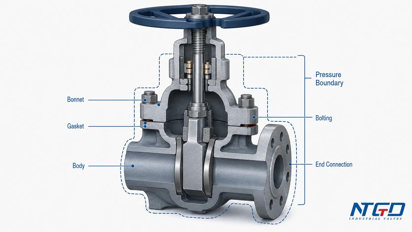
- Pressure boundary — body, bonnet, gasket, bolting, and end connections.
- Shutoff and sealing interface — gate / wedge and seat / seat ring.
- Operating and leakage-control system — stem, stem nut, yoke, packing, gland, handwheel, gearbox, or actuator.
How to Read a Gate Valve Parts Diagram
When reading a gate valve diagram, start with the pressure boundary. Identify the body, bonnet, end connections, gasket area, and bolting first because these parts contain pressure and connect the valve to the pipeline. Then move to the shutoff interface, where the gate or wedge contacts the seat. Finally, check the operating and leakage-control path, including the stem, packing, gland, handwheel, gearbox, or actuator.
This reading order helps engineers avoid confusing different failure modes. Body-bonnet leakage is not the same as seat leakage. Stem leakage is not the same as internal leakage across the gate. A clear diagram should help the reader separate these areas before reviewing materials, trim, or RFQ details.
The body forms the main shell around the flow passage. Inside the body, the gate or wedge moves up and down across the flow path. The seat or seat ring is the sealing surface where the gate contacts the body when the valve is closed. Above the body, the bonnet closes the upper part of the valve and supports the stem area. Around the stem, packing and a gland assembly help control leakage where the stem exits the pressure boundary.
A good gate valve parts diagram should not confuse a gate valve with a globe valve, ball valve, check valve, butterfly valve, or generic control valve. The key visual point is that the gate moves across a generally straight flow path to isolate flow, rather than rotating like a ball or disc.
What a Labeled Gate Valve Diagram Should Show
A useful labeled gate valve diagram should normally show:
- Body
- Bonnet
- Gate, wedge, or disc
- Seat or seat ring
- Stem
- Stem nut or yoke nut, if visible
- Packing
- Gland or gland follower
- Gasket at the body-bonnet joint
- Bolting, where applicable
- Handwheel, gearbox, or actuator
- End connection, such as flanged or welded ends
The exact appearance depends on the gate valve design. A forged steel gate valve, cast steel gate valve, resilient seated gate valve, pressure seal bonnet gate valve, or OS&Y gate valve may not look identical. The part names also vary slightly by manufacturer. That is why diagrams should be checked against the project datasheet and manufacturer drawing before procurement or maintenance decisions.
Gate Valve Parts and Functions Table
The table below summarizes common gate valve parts, their functions, key RFQ specification points, and common operational risks. It is intended to help buyers and engineers connect each component to a practical decision, not to replace a manufacturer-specific drawing or parts list.
| Gate Valve Part | Typical Location | Main Function | RFQ / Specification Note | Common Issue to Watch |
|---|---|---|---|---|
| Body | Main valve shell connected to the pipeline | Contains pressure and houses the internal flow passage | Confirm body material, end connection, size, pressure class, and design standard | Corrosion, erosion, casting or forging defects, body damage |
| Bonnet | Upper cover connected to the body | Closes the upper pressure boundary and supports the stem area | Confirm bonnet type, gasket design, bolting, and pressure-temperature suitability | Leakage at body-bonnet joint, bolt relaxation, gasket failure |
| Gate / Wedge / Disc | Inside the body, moving across the flow path | Opens or closes the flow passage | Confirm wedge type and whether the design suits the service media | Seat wear, jamming, surface damage |
| Seat / Seat Ring | Sealing area inside the body | Provides the sealing surface against the gate | Confirm seat design and trim material according to service | Leakage, wear, erosion, debris damage |
| Stem | Extends from operating device to gate | Transfers motion from handwheel, gearbox, or actuator to the gate | Confirm rising or non-rising stem design if relevant | Thread wear, bending, corrosion, difficult operation |
| Stem Nut / Yoke Nut | Around the stem or operating mechanism | Converts rotary motion into linear gate movement in many designs | Confirm design when operation method and torque matter | Wear, thread damage, high operating torque |
| Handwheel | Top of manual valve | Allows manual operation | Confirm manual operation suitability for size and torque | Broken handwheel, difficult operation |
| Gearbox | Between handwheel/actuator and stem on larger valves | Reduces operating effort or controls torque transmission | Confirm gearbox requirement for larger or high-torque valves | Gear wear, poor lubrication, difficult operation |
| Actuator | Top-mounted operating device | Enables electric, pneumatic, hydraulic, or remote operation | Confirm actuator type, control signal, fail position, and torque requirement | Incorrect sizing, delayed response, control mismatch |
| Packing | Around the stem inside stuffing box | Helps control external leakage along the stem | Confirm packing material suitable for media and temperature | Stem leakage, hardening, wear, over-compression, or temperature/media mismatch |
| Gland / Gland Follower | Compresses packing around stem | Maintains packing compression | Confirm accessible adjustment and material compatibility | Uneven compression, leakage, stem friction |
| Stuffing Box | Bonnet area around stem packing | Holds packing and supports stem sealing | Confirm design suitability for service pressure and temperature | Packing extrusion, leakage, corrosion |
| Gasket | Between body and bonnet or other joints | Seals static pressure joints | Confirm gasket type and material according to service | Joint leakage, blowout risk if incorrectly specified |
| Bolting | Body-bonnet joint or end connection | Holds pressure-retaining parts together | Confirm material and standard requirements for service | Loosening, corrosion, improper tightening |
| Yoke | External support for stem and operating parts | Supports rising stem or outside screw design | Confirm if OS&Y or rising stem visibility is required | Mechanical damage, misalignment |
| Backseat | Near the upper stem/bonnet area in some designs | May provide secondary stem-area sealing in specific fully open conditions | Confirm actual design and manufacturer instructions before relying on it | Misuse, wear, false assumption of isolation |
| Drain / Vent Plug | Optional body or bonnet connection | Draining, venting, or pressure release depending on design | Confirm if required by project specification | Plug leakage, corrosion, incorrect use |
The most important point is that a gate valve is not only a body, bonnet, gate, stem, and seat. For industrial service, packing, gland, gasket, bolting, stem nut, yoke, and actuator details can affect external leakage risk, maintenance frequency, operating torque, and RFQ accuracy.
Pressure Boundary, Sealing Interface and Operating Path
A practical way to understand gate valve structure is to divide the components into three functional groups.
| Structure Group | Included Parts | Main Role | Buyer Check |
|---|---|---|---|
| Pressure boundary | Body, bonnet, gasket, bolting, end connections | Contains internal pressure and connects the valve to the pipeline | Material, pressure class, end connection, standard, gasket design |
| Shutoff and sealing interface | Gate / wedge / disc, seat / seat ring, sealing surfaces | Stops or allows flow through the bore | Seat design, trim material, wedge type, service media |
| Operating and leakage-control path | Stem, stem nut, handwheel, gearbox, actuator, packing, gland, stuffing box | Moves the gate and controls leakage around the stem | Operation method, torque, stem design, packing material, accessibility |
This grouping helps prevent a common specification mistake: treating all valve parts as equal. A damaged handwheel is not the same risk as a damaged seat. A gasket issue is not the same as seat leakage. Each component belongs to a different function group, and each function group affects specification in a different way.
Why the Same Part Name May Vary by Valve Design
Different manufacturers and standards may use slightly different part names. For example, the moving shutoff member may be called a gate, wedge, disc, or obturator depending on the drawing or valve type. The stem sealing area may be described as packing, gland packing, stuffing box, or gland assembly.
This is normal, but it can create RFQ confusion. Describing the function and location of a part reduces the chance of name confusion between manufacturer drawings. For example, “stem packing suitable for the service temperature” is clearer than simply writing “packing” without service context.
Pressure-Retaining Parts: Body, Bonnet, Gasket and Bolting
Pressure-retaining parts form the external shell of the gate valve. These parts must contain internal pressure and maintain mechanical integrity under the service conditions. In a typical gate valve, the most important pressure-retaining parts are the body and bonnet, supported by gaskets, bolting, and end connections.
Valve Body
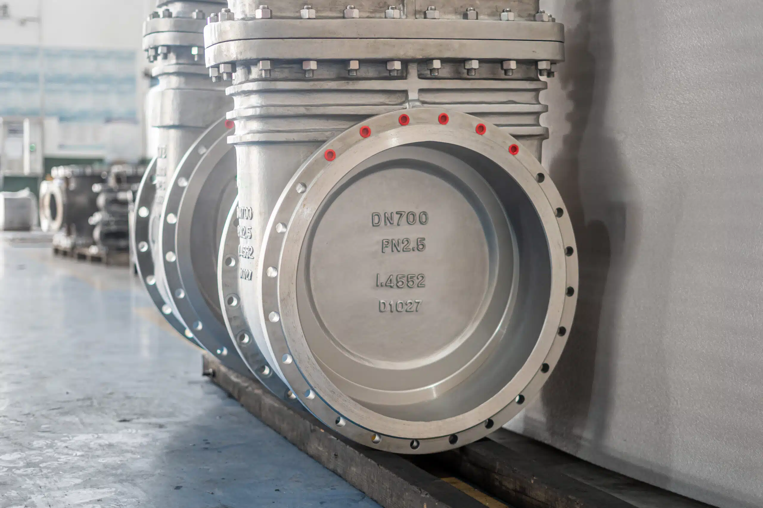
The valve body is the main shell of the gate valve. It contains the flow passage, supports the seats, houses the gate, and connects the valve to the pipeline. In many industrial designs, the body also defines the end connection type, such as flanged, butt-weld, socket-weld, threaded, or other project-specific connections.
The body affects several specification points:
- pressure class;
- body material;
- end connection;
- bore type;
- corrosion or erosion suitability;
- compatibility with service media;
- body-bonnet connection design.
For general industrial gate valves, body material may vary according to service requirements. Common material families can include cast steel, forged steel, stainless steel, ductile iron, or alloy materials, but the correct choice must be matched to the service media, temperature range, pressure class, corrosion risk, and applicable project specification. If the body material or pressure-boundary design is mismatched to the service, the result may be accelerated corrosion, external leakage risk, or pressure-integrity problems.
Bonnet and Body-Bonnet Joint
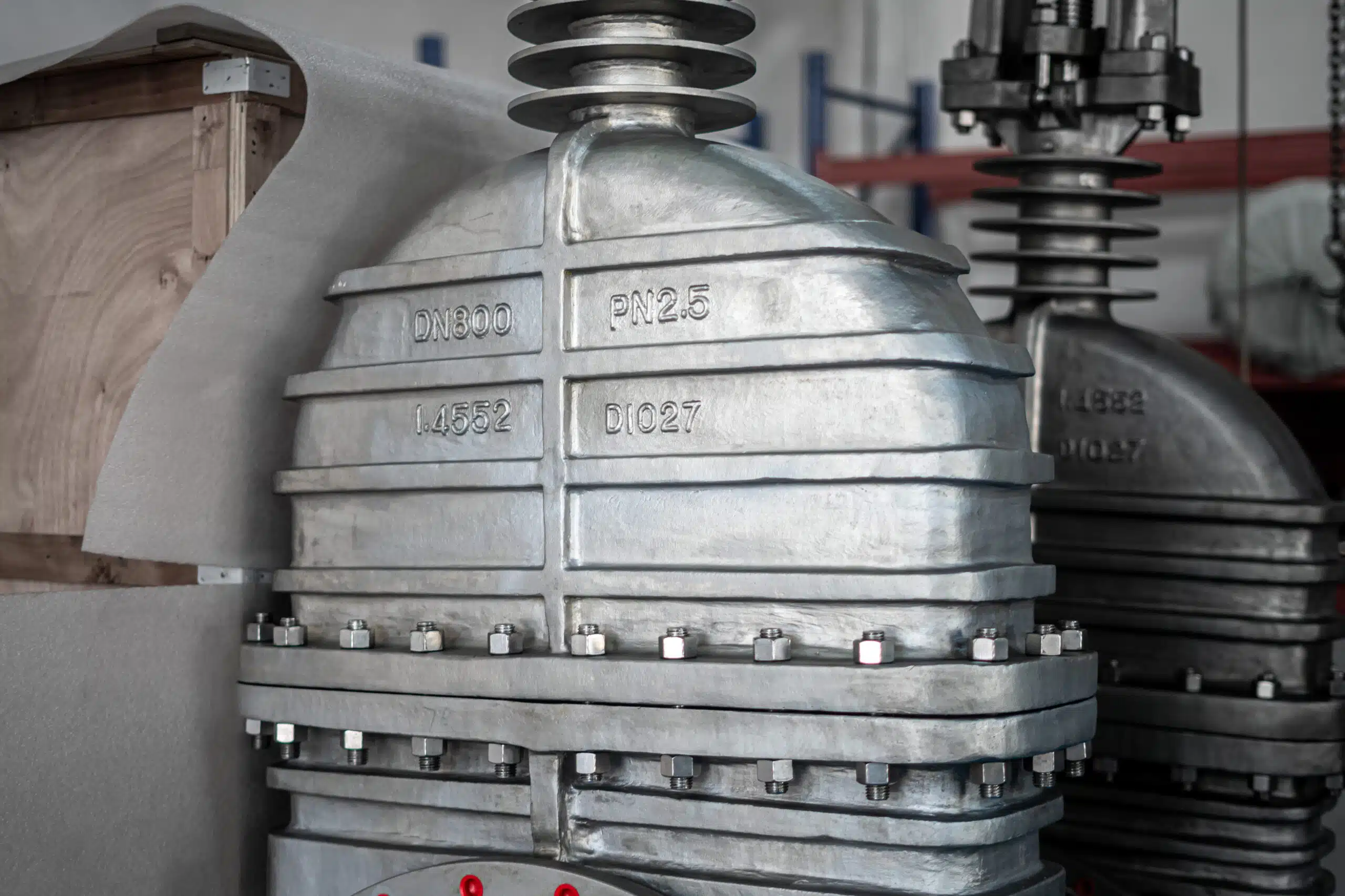
The bonnet closes the upper part of the valve body and supports the stem and packing area. It is part of the pressure boundary, not just a cover. The body-bonnet joint must seal reliably because leakage at this joint is an external leakage risk.
Bonnet design varies by valve type. Some gate valves use bolted bonnets, welded bonnets, threaded bonnets, or pressure seal bonnets. The current article does not expand bonnet types into a separate guide because bonnet selection depends on pressure class, temperature, service severity, maintenance expectations, and the manufacturer’s design. In this parts guide, the key point is that the bonnet must be reviewed as part of the pressure boundary and stem-sealing structure.
The body-bonnet joint should be reviewed together with the gasket and bolting. A suitable body material alone does not guarantee reliable sealing if the gasket, bolt material, tightening practice, or joint design is not appropriate for the service.
Gasket, Bolting and Pressure Boundary Details
Gaskets seal static joints such as the body-bonnet connection. Bolting holds the pressure-retaining parts together. These components may seem secondary, but they can strongly affect external leakage risk and maintenance reliability.
For industrial procurement, the gasket and bolting should not be treated as generic accessories. The exact gasket type and bolting material should be verified against the valve design, pressure class, temperature, fluid, and applicable project requirements.
Some gate valves also include a backseat feature near the upper stem area. A backseat may provide secondary sealing around the stem area under specific fully open conditions, but it should not be treated as a substitute for proper isolation, depressurization, or manufacturer-approved maintenance procedures.
A useful RFQ should confirm:
- body material;
- bonnet type;
- gasket material or sealing design;
- bolt / nut material requirements, if specified;
- pressure class;
- applicable design and testing standards;
- service media and temperature.
Shutoff and Sealing Parts: Wedge, Gate, Seat and Trim
The shutoff and sealing parts determine whether the gate valve can isolate flow properly. The key parts are the gate or wedge and the seat or seat ring. These parts form the internal sealing interface when the valve is closed.
Correctly separating the pressure boundary from the shutoff interface helps avoid specification mistakes. A valve may have a suitable body material but still leak internally if the gate-seat interface is not suitable for the media, temperature, pressure differential, or solids content.
Gate, Wedge or Disc
The gate is the moving shutoff member inside the valve body. In many industrial gate valves, this part is wedge-shaped, so it may be called a wedge. Some drawings may use the word disc. The function is the same in the context of this article: it moves across the flow path to open or close the valve.
When the valve opens, the gate moves upward and clears the flow passage. When the valve closes, the gate moves downward and contacts the seat surfaces. Because gate valves are designed mainly for isolation, they are normally used in fully open or fully closed positions.
The gate or wedge affects:
- shutoff performance;
- operating torque;
- seat contact pattern;
- wear behavior;
- suitability for clean, dirty, high-temperature, or abrasive service.
There are different gate designs, such as solid wedge, flexible wedge, split wedge, parallel gate, or other special structures. Specific wedge selection depends on service conditions such as pressure, temperature, media cleanliness, thermal expansion, and operating frequency. That belongs to gate valve selection or subtype design rather than basic parts identification, so this article only explains the gate or wedge as the general shutoff member.
Detailed wedge, parallel and knife-route comparisons belong in a separate gate valve types guide, while this section keeps the focus on the gate or wedge as the shutoff member.
Seat and Seat Ring
The seat is the sealing surface where the gate contacts the valve body. In some designs, the seat may be an integral part of the body. In others, separate seat rings may be installed. The exact construction depends on the valve design and manufacturer.
The seat is critical because it directly affects internal leakage. A gate valve can have a strong body and a functional stem, but if the gate-seat interface is damaged, contaminated, or incorrectly specified, shutoff performance may be affected.
Seat design should be reviewed according to:
- fluid type;
- temperature;
- pressure class;
- required shutoff performance;
- corrosion or erosion risk;
- trim material;
- whether the design is resilient seated or metal seated.
Seat wear or damage is a common cause of internal leakage because the gate can no longer contact the sealing surface correctly. In services with particles, high temperature, corrosion, or erosion risk, the seat and trim should be specified according to those conditions instead of relying on a generic “standard seat” description.
For a deeper comparison of soft-seal and hard-seal seat routes, see NTGD’s resilient seated vs metal seated gate valves guide.
What Are Gate Valve Trim Parts?
The word trim does not mean all gate valve parts. In many valve discussions, trim refers to the internal parts that are exposed to the fluid and are directly related to flow control or sealing. For a gate valve, trim commonly includes parts such as the gate or disc, seat or seat ring, stem, and related sealing surfaces.
However, trim definitions may vary by manufacturer, standard, and valve type. For that reason, an RFQ should not only say “standard trim” unless the project specification already defines what that means. A clearer request should identify the required trim material, seat design, stem material, and service conditions.
A simple rule is:
- Full parts = all components that make up the valve.
- Trim parts = selected internal parts, usually those in contact with the fluid or involved in sealing and movement.
Operating and Leakage-Control Parts
Operating parts move the gate. Leakage-control parts help prevent media from escaping along the stem or through static joints. These parts are important because a gate valve can fail to operate correctly even when the body, bonnet, gate, and seat are still structurally intact.
Stem, Stem Nut and Yoke
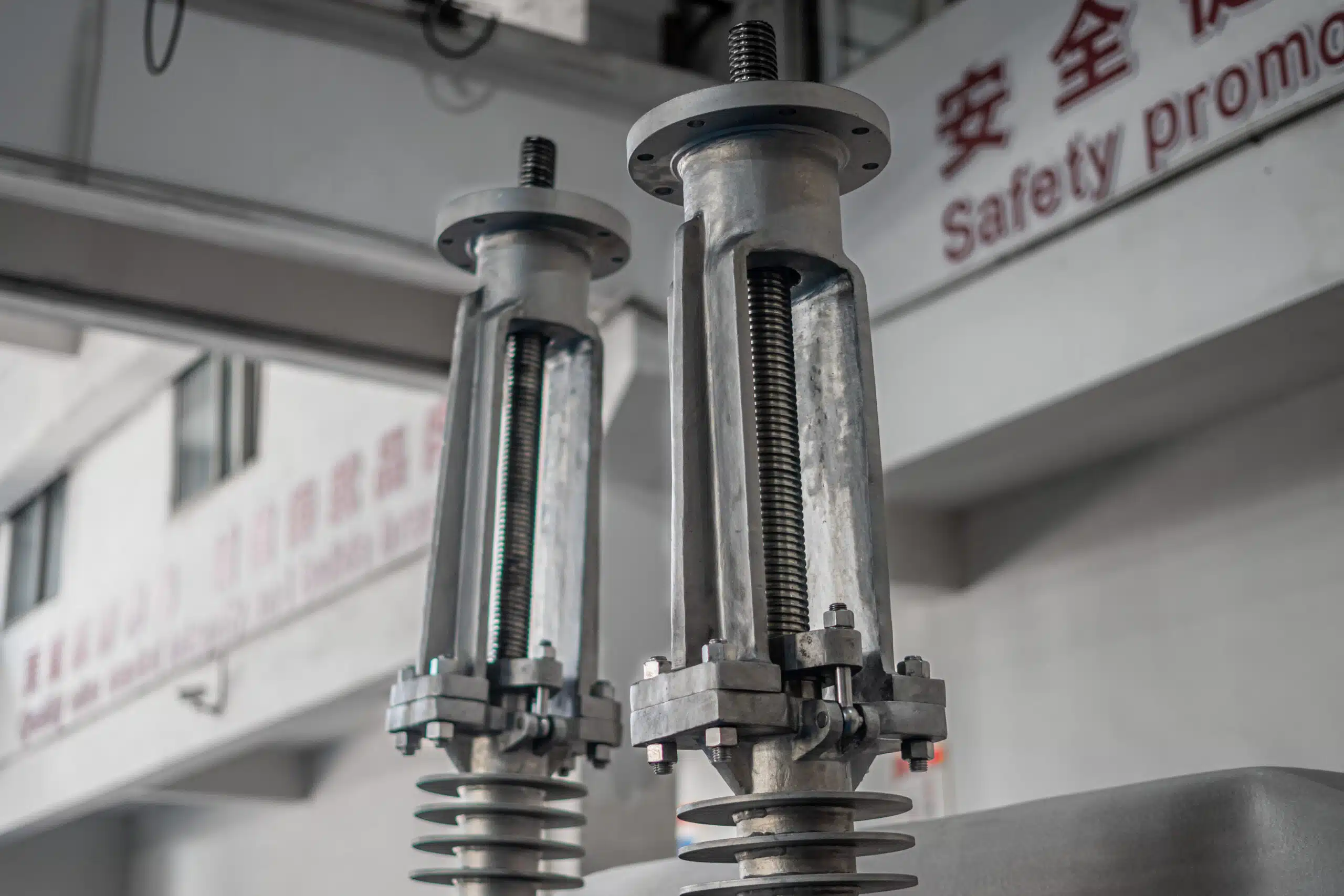
The stem connects the operating device to the gate. In many gate valve designs, turning the handwheel or actuator causes the stem or stem nut mechanism to move the gate up or down. The stem must transmit motion and force while remaining aligned with the gate.
Stem design affects:
- operating torque;
- valve position visibility;
- maintenance access;
- suitability for buried or above-ground service;
- compatibility with manual, gearbox, or actuator operation.
The stem nut converts rotary motion from the handwheel, gearbox, or actuator into linear movement of the gate in many gate valve designs. If the stem nut is worn or damaged, the valve may require excessive operating torque or may fail to open and close properly. The yoke provides structural support for the stem and operating mechanism, helping maintain alignment during operation.
If the drawing shows an outside screw and yoke arrangement, NTGD’s OS&Y valve guide can help confirm how visible stem travel relates to valve position.
Some gate valves use rising stems, while others use non-rising stems. That design difference is important, but it should not dominate this article. Here, the key point is that the stem is the motion-transfer component. Detailed comparison of rising stem and non-rising stem gate valves should be handled in a dedicated page or internal link.
Detailed stem-route selection should be reviewed in a dedicated rising stem vs non-rising stem gate valve comparison instead of being expanded inside a parts guide.
Handwheel, Gearbox and Actuator
The handwheel is the most common manual operating device for smaller or moderate-size gate valves. Larger valves or high-torque applications may require a gearbox. Automated systems may use electric, pneumatic, or hydraulic actuators, depending on project requirements.
The operating device should be selected according to:
- valve size;
- pressure class;
- operating torque;
- frequency of operation;
- installation position;
- accessibility;
- automation requirements;
- control system requirements.
This article does not become an actuator selection guide. The purpose is to show that the operating device is part of the gate valve component system. If the operation method is not specified correctly, the valve may be difficult to open or close, or may not match the control requirements of the pipeline system.
Packing, Gland and Stuffing Box
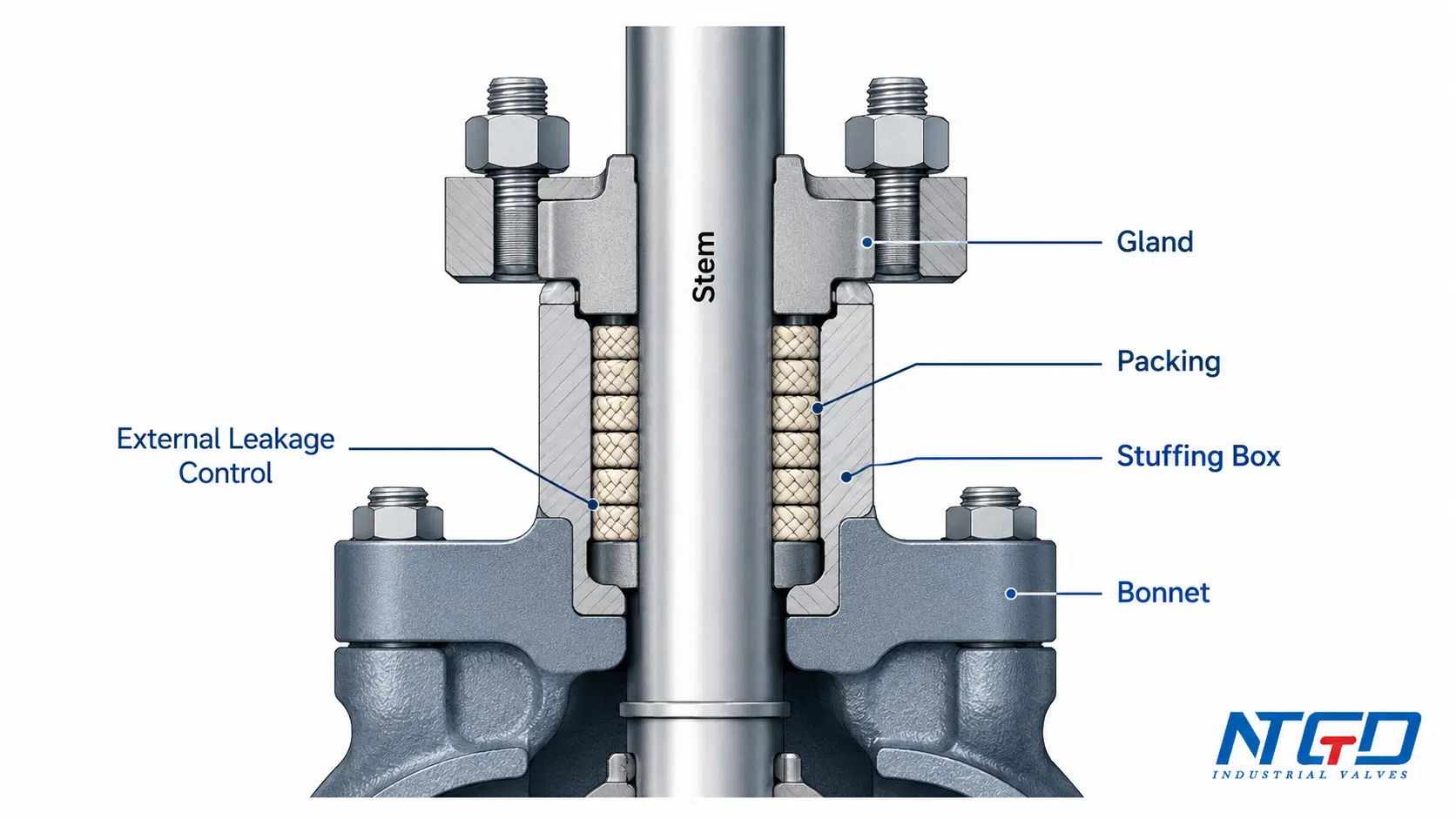
Packing is installed around the stem to control leakage to atmosphere. The packing is held and compressed by the gland or gland follower, and it is housed in the stuffing box area. This is one of the most important leakage-control zones in a gate valve.
The packing system must seal around a moving stem. Compression that is too low can cause stem leakage. Compression that is too high can increase operating torque, accelerate stem wear, or make the valve difficult to operate. The correct balance depends on valve design, packing material, pressure, temperature, media, and maintenance practice.
A buyer or engineer should confirm:
- packing material;
- gland design;
- accessibility for adjustment;
- suitability for service temperature and media;
- whether special leakage control requirements apply.
Packing, gland, and stuffing box details are often overlooked in basic gate valve parts lists. For industrial service, they should not be ignored because they directly affect external leakage control, maintenance access, and long-term operation.
How Gate Valve Parts Work Together
Gate valve parts work together through a simple but important sequence: the operating device turns or actuates the stem, the stem moves the gate, and the gate opens or closes against the seat. The body and bonnet contain pressure, while the packing and gasket systems help control external leakage.
For a step-by-step explanation of how rotary input becomes stem travel, gate movement, and final seat contact, see NTGD’s gate valve working principle guide.
Opening and Closing Movement
When a manual gate valve is operated, the handwheel turns the stem or stem nut mechanism. This movement raises or lowers the gate. When the gate moves upward, the flow path opens. When the gate moves downward, it contacts the seat surfaces and shuts off the flow.
This operating logic explains why the major parts cannot be selected independently. The gate must match the seat. The stem must match the operating device. The packing must seal around the stem while still allowing operation. The body and bonnet must contain pressure while supporting the internal moving parts.
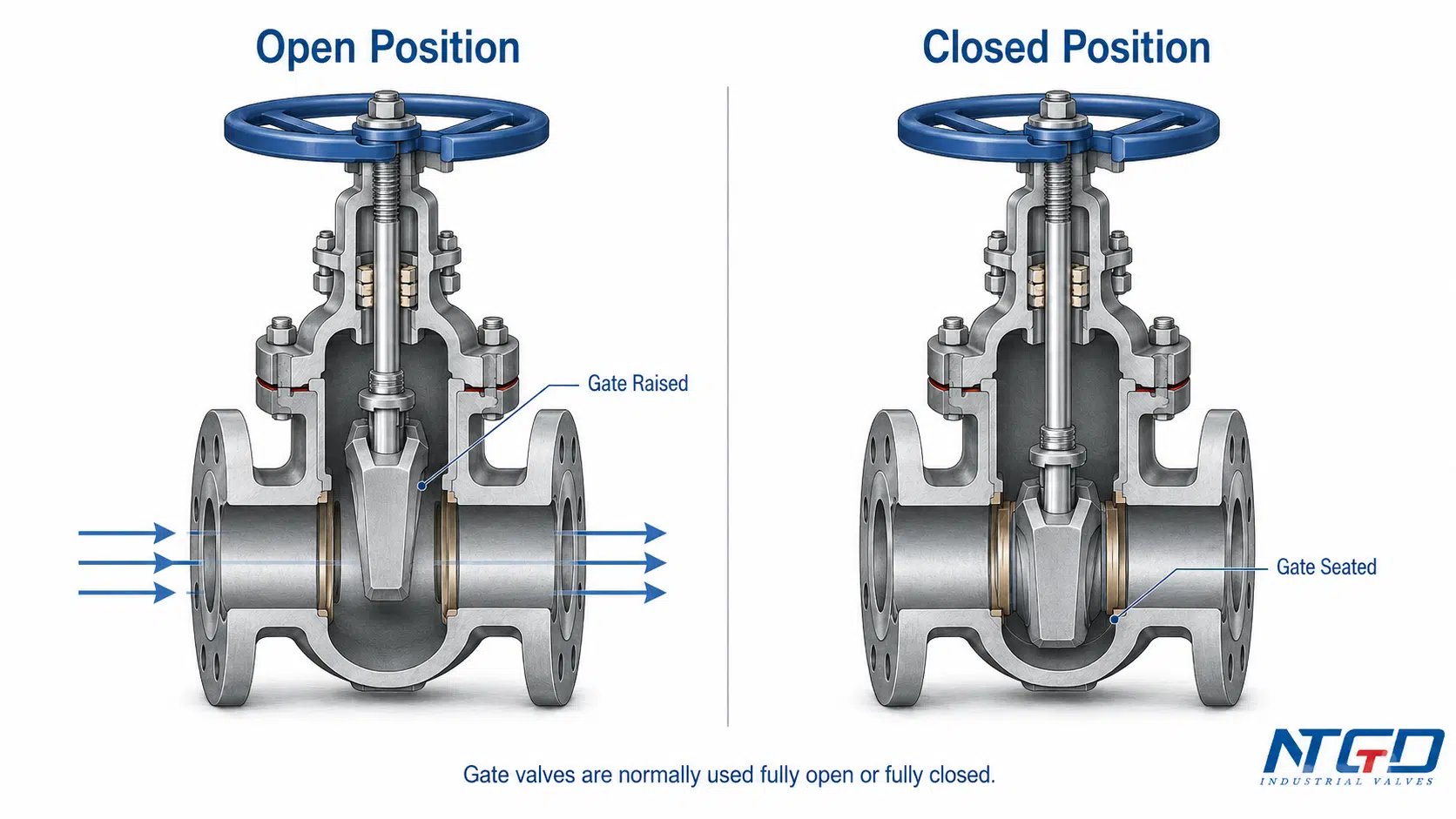
Why Gate Valves Are Normally Fully Open or Fully Closed
Gate valves are normally selected for isolation service. In the fully open position, the gate is lifted out of the main flow path. In the fully closed position, the gate contacts the seat to stop flow.
A gate valve should generally not be used as a throttling valve. In a partially open position, flow can concentrate around the lower edge of the gate and seat area. Depending on the service, this can cause vibration, erosion, noise, or seat damage. Over time, this type of operation may reduce shutoff reliability, increase maintenance exposure, and shorten the useful service life of the valve in demanding applications.
The DOE valve handbook reference also explains that a partially open gate can vibrate and accelerate disk and seat wear, which supports keeping gate valves in full-open or full-closed isolation service.
For applications that require frequent throttling or precise flow regulation, another valve type may be more suitable.
Structure Variants to Confirm Before RFQ
A gate valve parts guide should not become a full gate valve types guide, but some structure variants should still be confirmed before RFQ because they affect drawings, operation, and maintenance.
Key variants include:
- Gate / wedge design — solid wedge, flexible wedge, split wedge, parallel gate, or other design depending on service.
- Stem design — rising stem, non-rising stem, or OS&Y arrangement depending on position indication and installation needs.
- Bonnet design — bolted, welded, pressure seal, or other construction depending on pressure class and maintenance expectations.
- Seat design — metal seated, resilient seated, replaceable seat ring, or integral seat depending on valve type.
- Operation method — handwheel, gearbox, electric actuator, pneumatic actuator, or hydraulic actuator.
- End connection — flanged, butt-weld, socket-weld, threaded, or other connection.
These points belong in the RFQ checklist, not as long standalone sections in a parts guide. Expanding them too much would shift the article into a gate valve types or selection guide.
Common Part Issues and RFQ Specification Checklist
Understanding gate valve parts also helps identify what to check before purchase, inspection, or maintenance planning. This section is not a troubleshooting manual. It is a practical bridge between parts knowledge and industrial specification.
Common Component Issues to Watch
| Component Area | Possible Issue | Why It Matters | What to Confirm |
|---|---|---|---|
| Body | Corrosion, erosion, mechanical damage | Can affect pressure boundary integrity | Body material, service media, pressure class |
| Bonnet joint | External leakage | Can indicate gasket, bolting, or joint issue | Gasket type, bolting, tightening requirements |
| Gate / wedge | Surface damage or jamming | Can affect shutoff and operation | Wedge design, guide condition, media cleanliness |
| Seat / seat ring | Wear, erosion, debris damage | Can cause internal leakage | Seat material, service conditions, sealing requirement |
| Stem | Thread wear, bending, corrosion | Can make operation difficult or unreliable | Stem design, material, operation method |
| Packing / gland | Stem leakage or high friction | Can affect external leakage and operating torque | Packing material, gland adjustment, temperature |
| Handwheel / gearbox / actuator | Difficult operation or mismatch | Can prevent full opening or closing | Required torque, accessibility, automation needs |
| Gasket / bolting | Joint leakage or loosening | Can affect pressure boundary sealing | Gasket material, bolt material, assembly practice |
These issues show why an RFQ should describe the actual service conditions, not only the valve size. Service media, temperature, pressure class, operating frequency, installation position, and required documentation all affect which components and materials are suitable.
If the problem involves leakage, hard operation or incomplete travel, route the issue into a dedicated gate valve maintenance and troubleshooting review rather than turning this parts guide into a repair manual.
Gate Valve Parts RFQ Checklist
Each item in this checklist corresponds to a critical gate valve component or design feature discussed above. Providing complete and accurate information helps the manufacturer quote a valve construction that matches the required performance, safety, and durability conditions.
| RFQ Item | Why It Matters |
|---|---|
| Valve size | Determines body, bore, end connection, and operating torque |
| Pressure class / rating | Affects body, bonnet, bolting, gasket, and pressure boundary design |
| Body material | Must match service media, temperature, and corrosion requirements |
| Bonnet type | Affects pressure boundary, maintenance access, and service suitability |
| Wedge / gate type | Affects sealing behavior, operating torque, and service fit |
| Seat / trim material | Affects shutoff, wear resistance, corrosion resistance, and temperature suitability |
| Stem design | Rising or non-rising design affects operation, visibility, and installation |
| Operation method | Manual, gearbox, electric, pneumatic, or hydraulic operation changes topworks and torque requirements |
| End connection | Must match pipeline connection and installation requirement |
| Design / testing standard | Should be verified against project specification and applicable gate valve standards when required |
| Service media | Affects material, seat, trim, packing, gasket, and corrosion decisions |
| Temperature | Affects body, trim, gasket, packing, and bolting selection |
| Documentation requirements | May include drawings, material certificates, test reports, inspection records, or project-specific documents |
For steel bolted-bonnet gate valve projects, API’s current notices confirm that API Standard 600 is maintained under API’s program updates, so the applicable edition and project standard should be verified before procurement.
A clear RFQ should connect each part to the service condition. For example, seat and trim material should not be chosen separately from media and temperature. Operation method should not be chosen separately from torque and accessibility. Packing and gasket should not be treated as generic items when leakage control matters.
When project documentation requires API-related language, NTGD’s API standards for gate valves guide can help separate design, testing and documentation references before the final RFQ.
When to Refer to Manufacturer Documents
Manufacturer drawings, datasheets, IOM manuals, and project specifications should be used when exact part identification is required. This is especially important for replacement, repair, or maintenance work.
A general article can explain where the body, bonnet, stem, gate, seat, packing, and gasket are located. It cannot confirm the exact part number, material, dimension, or replacement method for every valve model. Those details must come from the specific manufacturer document or approved project drawing.
FAQ
What are the main parts of a gate valve?
The main parts of a gate valve usually include the body, bonnet, gate or wedge, seat, stem, packing, gland, gasket, and an operating device such as a handwheel, gearbox, or actuator. Industrial designs may also include a yoke, stem nut, backseat, drain plug, vent plug, or special sealing parts.
What are the components of a gate valve?
Gate valve components can be grouped into pressure-retaining parts, shutoff and sealing parts, operating parts, and leakage-control parts. The body and bonnet contain pressure. The gate and seat shut off flow. The stem and handwheel or actuator move the gate. Packing, gland, gasket, and bolting help control leakage.
What are the trim parts of a gate valve?
Gate valve trim usually refers to selected internal parts exposed to the fluid or involved in sealing and movement. It commonly includes the gate or disc, seat or seat ring, stem, and related sealing surfaces. The exact definition can vary, so trim material should be confirmed against the datasheet or project specification.
What part seals a gate valve?
The gate and seat create the internal shutoff seal. The packing, gland, gasket, and body-bonnet joint control external leakage at different locations. These sealing areas should not be confused because internal leakage and external leakage have different causes and different inspection requirements.
What does the stem do in a gate valve?
The stem transfers motion from the handwheel, gearbox, or actuator to the gate. Depending on the design, the stem or stem nut mechanism raises or lowers the gate to open or close the valve. Stem design affects operation, position indication, maintenance access, and installation requirements.
How does a gate valve work?
A gate valve works by moving a gate or wedge up and down across the flow path. When the gate is raised, the flow path opens. When it is lowered against the seat, the valve closes. Gate valves are normally used for fully open or fully closed isolation service, not for precise throttling.
Can gate valve parts be replaced?
Some gate valve parts may be replaceable depending on the specific valve design, manufacturer, and service condition. However, this article is a general industrial parts guide, not a replacement parts catalog or repair manual. Not every seat ring, stem, packing set, or bonnet component is designed for simple field replacement, so all replacement work should follow manufacturer-approved parts, official IOM documents, and project safety procedures.
Is a gate valve diagram the same as a P&ID symbol?
No. A gate valve parts diagram shows the physical structure and labeled components of the valve, such as the body, bonnet, stem, gate, and seat. A P&ID symbol is a simplified schematic symbol used in piping and instrumentation drawings. This article focuses on physical parts diagrams, not P&ID symbols.
Conclusion
Gate valve parts should be understood as a working system, not as isolated names on a drawing. The body and bonnet form the pressure boundary. The gate or wedge and seat form the shutoff interface. The stem, stem nut, yoke, handwheel, gearbox, or actuator move the gate. Packing, gland, gasket, and bolting help control leakage and maintain pressure integrity.
For industrial buyers, this structure matters because each part affects a specification decision. A clear RFQ should connect component requirements to service media, pressure class, temperature, material, operation method, standards, and documentation needs.
Application / Specification Support
NTGD can review gate valve requirements based on project media, pressure, temperature, material, operation method, and documentation needs to help match the correct parts and construction to the service conditions.
For broader valve-function screening before specifying a gate valve, NTGD’s industrial valve selection guide can help confirm whether the application needs isolation, throttling, backflow prevention or another valve function.
For a reliable quotation, provide the service conditions and required specifications rather than only a part name or a general valve type.
